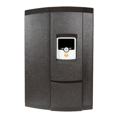
Tollco WaterFuse Apartment Manual

1(16)
WaterFuse® - Apartment
User Manual
&
Installaon Instrucons

2(16)
Thank you for choosing to the WaterFuse® automatic water shut-off valve.
We hope that WaterFuse® will live up to your expectations as a simple yet
effective protection against water damage caused by pipe or equipment
damage. The manual is divided into two parts, one for the user and one for
the installer, in order to provide simple and clear instructions for the user and
the necessary information for the installer.
Safety
Read this manual carefully and follow the instructions for placement and
usage.
The product may only be connected by a qualified installer. The warranty does
not cover repairs of faults caused by faulty installation or incorrect use of the
appliance.
The ball valves have been tested by Sintef, in accordance with EN 13828 and
NT VVS 094
Recycling
Used products must be left at a collection point for the recycling of electrical
and electronic components. By ensuring that the product is handled correctly,
you help to prevent any negative environmental and health effects that may
occur if the product is disposed of as normal waste. For further information
on recycling, please contact local authorities, your household waste disposal
service, or the shop where you purchased the item.
Edition 11/02/2020
!

3(16)
Table of Contents
1. User Manual 4
1.1. General Information 4
1.2. The Different Parts 5
1.3. Daily Operation 6
1.4. Alarm 7
1.5. Faults 7
1.6. External Control 7
2. Installation Instructions 8
2.1. General 8
2.2. Installation 8
2.3. Settings 10
2.4. Connection to Alarm 11
or Other Remote Controls
2.5. Connecting the Cables 12
2.6. Connecting Wireless Devices 13
3. Technical Specification 14
4. Warranty and Limitation of Liability 15

4(16)
User Manual
1.1 General Information:
WaterFuse® - Apartment reduces the risk of water damage in the apartment and the
property through the utilisation of a control unit which shuts off incoming water when
water is indicated in the water distribution cabinet or under the dishwasher/sink. You
can also easily turn off the water manually or via external control.
The ball valves are fitted on incoming cold and hot water to the apartment and are
connected to the control unit via cables. A wired sensor for water indication is placed
at the point where the water is distributed to the apartment (water distribution
cabinet) and wireless water detectors can be placed under the dishwasher or sink.
The water detectors function as a smoke alarm, but with water. If they indicate water,
a signal is sent to the central unit which switches off the water automatically. The
remote unit is placed by the front door to easily turn the water on and off manually.
Components
– Central unit, art. no. 2220082
– Motorised ball valve, art. no. 2130051 (DN15)
– Water sensor – DC adapter – manual
– Wireless water detectors art.no 2220042 (optional)
– Remote unit art.no. 2220022 (optional)
The motorised ball valves may be ordered, DN15 or DN20.
The product is delivered in different package combinations; the above items are not
always included.
The products are marked with a label stating the article number and date of
manufacture.

5(16)
1.2 The Different Parts:
The central unit:
The central unit controls the ball valves and monitors leaks in the water
distribution cabinet with the help of water sensors. It also receives
signals from the wireless devices.
Installed in a suitable place near the water distribution cabinet.
Motorised Ball Valves:
Motorised ball valves to turn water supply ON and OFF.
The units are intended for tap water, 0-60°C and 0-10 bar.
If the power goes out, they can also be operated manually
with a mechanical knob on the unit. Lift the knob 5 mm and
turn clockwise to close the valve. The indicator next to the
knob shows open/closed.
Fitted in the water distribution cabinet.
Water sensor:
The water sensor is placed in the water distribution cabinet
and when water is indicated, the control unit will switch off
incoming water.
Fitted in the water distribution cabinet.
Remote unit: (optional)
From here you can easily turn the water off and on with a wireless signal to
the control unit.
Place by the front door.
Water detector: (optional)
Each water detector comes with three sensors which are
positioned in suitable places. The water detector sends a radio
signal to the central unit and beeps with pulsing sound signals
when it detects water. The water detector sends an "I am alive"
signal every 24 hours to the central unit.
Below are several different installation suggestions:

6(16)
Under the dishwasher and sink or kitchen island with a sink:
One sensor on the plastic mat under the dishwasher, one sensor on the floor under
the sink, and one in the shaft where the pipes come up from the floor or in the
floor sill.
Under a fridge / freezer with water supply:
One sensor under the appliance which is to be monitored.
In the laundry room or bathroom:
In these areas, there is sometimes water splashing
during regular use; the floor must be waterproofed
and there must be a functioning floor drain. Place the
sensor (or sensors) where they will only touch water
in case of a leak resulting in rising water level, for
example in the threshold.
1.3 Daily Operation:
Monitoring of the water system takes place continuously and no daily measures
need to be taken. If external control is used, see section 1.6
If the central unit or remote unit is used to switch the water on and off daily, see
below.
Turn the water on
• Press ON. Green light indicates that the water is on.
Turn the water off
• Press OFF. Red light indicates that the water is off.
Delayed shutoff of the water
• Press DELAYED OFF. Red light indicates that the water will turn off after
a while.
• The time until the water is switched off is set with the DIL switches, see
section 2.3. (Factory setting 2h) Pressing DELAYED OFF again reloads the
timer with the set time.

7(16)
1.4 Alarm:
The water sensor indicates water
• Indication of water from the water sensor or wireless water detector.
The ball valves close automatically, and the control unit sets to the OFF
position. The ALARM LED flashes, and the buzzer pulsates.
• Resolve the leak and confirm the alarm by pressing OFF. As long as one
of the water sensors is wet, the system will turn off again.
1.5 Faults:
• Low battery voltage.
If the battery voltage gets too low in any of the battery-powered units, it will
beep in a way similar to a smoke alarm.
During normal use, the batteries have a life expectancy of at least 2 years.
• Radio communication errors
If the radio communication between different devices stops working, or does
not work satisfactorily, this is usually because something has changed in the
home since the radio communication last worked. Something new has been
introduced that interferes with the transmission; tin cans under the sink
that block the signal is the most common problem, but new wires or electric
equipment within 30 cm from one of the radio units could also be the cause.
1.6 External Control:
See instructions or manual for these devices. Note that the keystroke / control
signals override the previous ones. Connect according to the description in
section 2.4.

8(16)
2 Assembly Instrucons
2.1 General:
The product must be installed by a person who has the professional knowledge
required to perform the installation correctly. Unless the installation is performed
by a professional, the insurance companies may claim that the insurance does
not cover any damage that has occurred and that the offers made by the
insurance companies to the property owner are invalid.
If the ball valves are open for more than three days, they are exercised
automatically. This is done by partially closing the ball valves and then opening
them once. The water is never completely shut off. The water detectors
send signals every day which are registered by the control unit. If no signal
is perceived by the control unit for 72 hours, the control unit warns that
communication is down.
A total of 16 external units can be installed, mixed freely between remote devices
and water detectors.
A washing machine can be placed in the kitchen without a floor drain, if there
is a waterproof surface and a water detector connected to a water switch, by
wire or wireless, is placed so that any water leaking from the equipment can be
detected so that the leak can be automatically stopped. (According to Safe Water
Installation 2016: 1 Section 3.6.3) This of course also applies to other pressurised
equipment such as dishwashers, coffee machines, and refrigerators / freezers
with automatic water supply.
The products are marked with a label stating the article number and the date of
manufacture.
2.2 Installation:
Motorised Ball Valves: (art.no. 2130051 if DN15 is used)
The units are intended for tap water, 0-60°C and 0-10 bar.
Mount on cold and hot water. They can be mounted horizontally, vertically,
or upside down and independent of flow direction. The unit has an internal
R-thread. Connect them to pipes, for example with compression fittings. Use the
required sealant.
The units must not be mounted in a concealed place; they must be placed so that

9(16)
they are replaceable and so that any leaking water can be easily detected. The
units must be installed in rooms with a waterproof floor, in a distribution cabinet,
or in a custom space. If a distribution cabinet is used, the installation instructions
for this must be followed. After mounting, the installation must be checked for
leaks with the tap water installation's existing water pressure according to the
instructions on www.säkervatten.se
Central unit: (art. no. 2220082)
Mount in a suitable place near the motorised ball valve.
The box has a "button" on the underside that is used to open it.
Do not install inside a metal water distribution cabinet as this will weaken
the radio signals to the wireless units.
The supplied DC adapter can be used for power supply or if the property
has 12vdc, it is connected via a terminal block on the circuit board.
The cable from the motorised ball valve is drawn to the central unit and
connected to the 6-pole terminal K80 on V1 and V2 with the red cable to +. The
cable from the water sensor goes to the central unit where it is plugged in to Prb
on terminal block K81. All cables can be connected at the back of the central unit
to avoid visible wiring, disconnect the centre plate on the mounting plate and
connect the cables to the terminals. See Section 2.5.
Water sensor:
The supplied water sensor is placed in the water distribution cabinet and
connected to terminal K81, Prb. Alternatively, connect to the contact on the
bottom of the unit.
Water detector: (art. no. 2220042)
The accompanying sensors are placed in the area intended to be
protected. For example by the dishwasher and sink: One sensor on the
tray that should be underneath the dishwasher, one sensor on the floor
underneath the sink and the final sensor in the shaft where the pipes
emerge from the floor. For more installation suggestions, see section
1.2.
The box has a "button" on the underside that is used to open it. Install
two new AA batteries in the battery compartment as instructed. The
back piece is screwed to the wall. Check that there are no electrical cables or
"Button"

10(16)
installations within 50 cm of the device as this impairs the radio transmission.
Remote unit: (art. no. 2220022)
Place in an easily accessible place near the front door.
The box has a "button" on the underside that is used to open it.
Install two new AA batteries in the battery compartment as
instructed. The back piece is screwed to the wall.
Check that there are no electrical cables or installations within 50
cm of the device as this impairs the radio transmission.
2.3 Settings:
There are a number of settings that can be changed for the product.
Settings are changed with dip switches on the central unit circuit board.
Changes to the dip switches are easily made by using a pen or a small
screwdriver to move the switch. The black marking below shows the plastic
switch you are moving. The plastic switch can be black, white, or blue.
"Button"

11(16)
2.4 Connection to Alarm or Other Remote Controls
WaterFuse® Apartment can be connected to a master alarm or property
control system and thus becomes part of that system. This allows you to turn
the water to the equipment on and off automatically.
The input port uses optocouplers to protect the electronics.
Suggestion for connection to external controls:
• Jumper + Out with + Ext. Install switch between –Ext and 0v.
• When the switch is closed, the optocoupler / signal is activated and the
water is turned on.
• When the switch is opened, the optocoupler / signal is deactivated and
the water is turned off immediately or with a delay according to DIL
switch 4.

12(16)
2.5 Connecting the Cables:
All terminal blocks for the ball valves are parallel. This means that you can
connect valves as it suits you, you can also connect two valves in parallel in
one terminal if it is more suitable.
Terminal block - K80
Ball valve 1 is connected to V1. Red on +.
Ball valve 2 is connected to V2. Red on +.
External voltage supply between +12/24 and 0v
Terminal block - K81
Water sensor between Prb and Prb.
External control of on / off with + Out, 0v, + Ext, -Ext.
+Out = the voltage fed to the control unit (12/ 24vdc)
0 v = 0 v to terminal block K80
+ Ext, -Ext = Connection to optocoupler
Terminal block - K82
Ball valve 3 is connected to V3. Red on +. (For extra ball valves)

13(16)
2.6 Connecting Wireless Devices
Switch between normal mode and installation mode:
Press and hold ON and DELAYED OFF simultaneously for 3 seconds to switch modes.
A short beep indicates the shift.
The ALARM LED is constantly lit when the unit is in the installation mode.
Press DELAYED OFF to see how many wireless devices are installed. The number of
flashes corresponds to the number of wireless devices. A long beep indicates that no
wireless devices are installed.
Press and hold ON and DELAYED OFF simultaneously for 3 seconds to switch back to
normal mode.
Installing the remote unit and water detector:
Switch to installation mode as above.
Put the remote unit / water detector in installation mode by restarting it. (Remove
the batteries, wait 1 minute, plug in the batteries, the unit beeps, the installation
mode automatically switches to normal mode after 5 minutes)
When the control unit receives the installation signal, ON flashes green.
Press ON to install the device. A short beep and a ON flashing green indicate that
the unit has been added.
If OFF instead flashes red, no more units can be installed. A maximum of 16 wireless
units can be installed.
Press DELAYED OFF to see how many wireless devices are installed. The number of
flashes corresponds to the number of wireless devices. A long beep indicates that no
wireless devices are installed.
Uninstalling the remote unit and water detector:
Switch to installation mode as above.
Individual devices cannot be deleted. All devices are deleted at the same time.
Afterwards you need to put all the remaining units back as above.
Press and hold OFF for three seconds. All units are deleted, and the deletion is
confirmed with a long beep and OFF flashing red.

14(16)
3 Technical Specicaons
EL VHP
230 vac for 12v dc adapter G15, G20,
(DN15, DN20)
2 × AA 1.5v batteries for remote unit Motorised ball valves with
manual override
2 × AA 1.5v batteries for water detector
Battery life is expected to exceed 2 years.
Radio transmission up to 40 meters indoors, depending on building materials
in the property.

15(16)
4 Warranty and Limitaon of Liability
In addition to the terms of the Consumer Purchase Act, a 1-year functional warranty is
provided for the product.
The warranty stipulates that during normal use and maintenance, the product must be
free from defects in design and function. The warranty period is calculated from the date
of purchase, which must be proven by a receipt from the place of purchase. The warranty
presupposes that the product has been installed appropriately and in accordance with
the written instructions. The plumbing installation must be completed by a plumber.
If you have questions or problems with your product, you should first contact the dealer
who sold or installed your equipment. Before you report a fault /complaint about your
broken product, please read the operating instructions and, if possible, check that all
settings are correct. The warranty stipulates that defective parts or components will be
replaced with defect-free ditto. The customer is responsible for all overhead, unless the
Consumer Sales Act is applicable. This means that shipping costs, inspection, and assem-
bly costs are not included in the warranty commitment.
If possible, use the original packaging if the product needs to be transported.
The transport companies do not compensate for damage if the product has been poorly
packaged.
The warranty does not apply to defects that occur during or after making your own
changes to the product's function or appearance, such as rebuilding, upgrading, or other
configurations of the product made without written approval.
The warranty does not cover faults that have arisen through an accident or malicious
damage.
The warranty does not cover deterioration that has occurred after the purchase, if
the seller can prove it probable that the deterioration is due to neglected or incorrect
maintenance or that the appliance has been used for something other than its intended
purpose, that inappropriate measures, unauthorised or incorrect interventions have been
made or that installation instructions were not followed.
Batteries are considered consumables and are not covered by the warranty.
The reseller is not responsible for loss or damage of any kind caused by this
product. The liability is, in any case, strictly limited to the replacement of the product.

16(16)
Tel:018-349010
info@tollco.se
www.tollco.se
Tollco AB
Rubanksgatan 4
741 71 Knivsta
Table of contents
Popular Water System manuals by other brands
AL-KO
AL-KO HW 5000 FMS Premium Original instructions for use
Yamato
Yamato Neocool CF302L-A instruction manual
AquaLiv
AquaLiv A305 Usage & installation instructions

Clearwater Spas
Clearwater Spas Genesis Blu Fusion manual
Katadyn
Katadyn POWERSURVIVOR 160E Fact sheet
salmson
salmson THERMO'CLOCK Installation and starting instructions
LIFE Ionizer
LIFE Ionizer M7 UC user manual
Filtrine
Filtrine B103 Maintenance instructions
GE
GE GXSG30V Owner's manual and installation instructions
Westomatic
Westomatic HYDRATION STATION Installation & maintenance guide

FLOWMARK
FLOWMARK Mark-II-SC Installation & operation manual

GE
GE Autotrol Performa ProSoft 960 Series Installating and operation manual
