Tolomatic CC50 Instruction Manual

• URL: http://www.tolomatic.com • Email: [email protected] • Fax: (763) 478-8080 • Toll Free: 1-800-328-2174
1001-4006_04
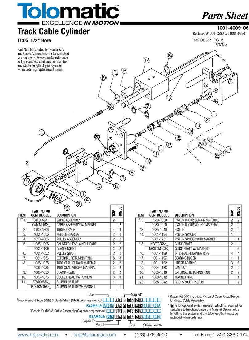
Cable Cylinders
5-INCH BORE
MODELS: CC50 SA50
CC50HK/HL SAS50
Item Part No. Description
RKCC50
Repair Kit (specify stroke)
1
RKSA50
Repair Kit (specify stroke)
1
1. 1014-1023 Retaining Ring 2 1
2. 1004-1056 Retaining Ring 4 2
*3. CACC50
Cable Assembly (specify stroke)
2
CASA50
Cable Assembly (specify stroke) 1
*4. 1037-1014 O-ring 2 1
5. 1037-1010 Retaining Ring 2 2
6. 1037-1007 Tube 1 1
*7. 1037-1013 Wear Ring 2 2
*8. 1037-1012 U-cup 2 1
9. 1037-1016 Piston 1 1
10. 1037-1004 Clamp Plate 2 2
11. 1037-1020 Single Ported Head 2 1
12. 1004-1055 Bearing 6 3
Item Part No. Description
13. 1004-1053 Washer 4 2
14. 1037-1018 Pulley 2 1
15. 1037-1009 Pulley Shaft 2 1
16. 2324-1004 Lock Nut 2 1
17. 1037-1028 Clevis 1 1
18. 1310-3110 Socket Head Cap Screw 8 8
22. 1037-1038 Bumper NA 1
23. 1037-1043 FTG, Pipe, Breather NA 1
24. 1037-1037 End Plate NA 1
*Contained in Repair Kit.
Parts Listing
CC50
SA50
CC50
SA50
Part Numbers noted for Repair Kits and Cable
Assemblies are for standard cylinders only.
Always make reference to the complete
configuration number and stroke length of your
cylinder when ordering replacement items.
11
1
9
8
7
6
5
4
2
10
12
13
14
15
18
17
16
3
10
18
23
24
5
22
9
Parts Sheet

• URL: http://www.tolomatic.com • Email: [email protected] • Fax: (763) 478-8080 • Toll Free: 1-800-328-2174
2 – General Installation and Maintenance Instructions CC50 Parts Sheet #1001-4006_04
INSTALLATION
When unpacking a Tolomatic cable cylinder, BE EXTRA CAREFUL NOT
TO SCRATCH OR MAR THE NYLON COVERING ON THE CABLE. The
cylinder may be mounted using the bolt holes in the head. When attaching
the cable bracket to the driven mechanism, be sure it is in perfect alignment
and that it does not deflect the cable to the side. Misalignment can cause
excessive wear.
Pretensioning and proof-loading instructions: All double-acting cable
cylinders are shipped without being pretensioned. They must be preten-
sioned after mounting to insure maximum service life of the device. There
are two types of stretch in cable— constructional and elastic. The construc-
tional stretch is removed by proof-loading of the cable. The elastic stretch is
removed by proper pretensioning of the cable.
Proof-loading of cables (for cylinders without Auto Tensioners):
1. Tighten the bracket terminal lock nuts equally with a torque
wrench to torque requirements listed in Table A.
2. Let set for 30 seconds.
3. Loosen lock nuts to remove tension. (But leave them tight
enough to eliminate any slack.)
4. Follow Pretensioning Instructions.
TABLE A: TORQUE TO PROOF-LOAD THE CABLE
MODEL REQUIRED TORQUE
CC50 325 inch-pounds OR 36.72 Newton-meters
Pretensioning of cables:
1. Block the load some distance from the end of travel to keep cyl-
inder from bottoming.
2. Apply pressure that is 15-20 percent higher than actual load
pressure needed to move the load.
NOTE: When the load is stopped externally before the piston bot-
toms, the relief valve or regulator setting becomes the load pres-
sure.
WARNING: The CC50 cable cylinder develops up to 1919
pounds of force at 100 PSI. Be certain the materials used to
block the load are sufficient to withstand these forces.
When pressurized, one cable becomes tight and the other
becomes slack. Manually adjust out the slack. Release the pres-
sure. Block the load on the opposite side and pressurize the
other port. Repeat the manual adjustment on the other cable.
Release pressure and remove blocks. Return the regulator or
relief valve to the original load pressure.
The cylinder is now pretensioned. Additional manual adjustment
should not be required. It is suggested however, that the cables be
checked periodically.
Alternate Method: If the load cannot be blocked for cable preten-
sioning as stated above, tighten the bracket terminal lock nuts with
a torque wrench to total pretensioning torque as stated in Table B.
TABLE B
Pretensioning + Starting Torque of = Total
Model Torque Terminal Nuts Pretensioning Torque
CC50 180.0 in-lbs. + 30.0 in.-lbs. = 210.0 in.-lbs.
20.34 N-m + 3.38 N-m = 23.72 N-m
NOTE: For cylinders with Auto Tensioners, the cables must be proof-load-
ed and pretensioned before pressure is applied to the AT unit.
TO REBUILD THE CYLINDER
1. Remove cylinder from machinery.
2. Disconnect Cable (21) from the Clevis (17) and remove Pulleys (14)
on both ends of the cylinder.
3. Remove internal retaining rings (2) from both heads and remove one
head from cylinder by removing the four Socket Head Cap Screws
(18)
4. Pull Piston (9) towards the opened tube end and remove from Tube
(6).
5. Disconnect Cables (21) from Piston (9) and pull back through the
Heads (11) with their Gland Seals (3) to remove them.
6. Install new U-cups (8) and O-rings (4) on piston (9) and rethread new
Cables (21) through Heads (11), and connect them to the Piston (9).
7. Being careful not to damage the cable, lubricate and install the Gland
Seals (3) in the Heads (11), and reinstall the retaining rings (2).
8. Push the piston back into tube by gently tucking in the U-cup (8) with a
screwdriver or pencil. Mount head back on cylinder with socket head
cap screws (18). Replace the Pulleys (14) and connect cable (21) to
the clevis (17).
9. Operate cylinder back and forth by hand several times to be sure it is
properly assembled before reconnecting air or hydraulic service.
10. Reinstall cylinder on machinery.
IMPORTANT NOTE: Apply (Blue) Loctite® #242 or equivalent to threaded
cable terminal before connecting to the piston.
MAINTENANCE
Keep the cylinder as clean as possible around pulleys, glands, etc.
Pneumatic service should be adequately lubricated with SAE 10 or 20
grade non-detergent oil.
Pulleys have permanently lubricated bearings and will require no mainte-
nance. Check the cylinder’s cables periodically to help prevent premature or
unexpected failures.
Your Tolomatic Cable Cylinder will give you many cycles of trouble free ser-
vice. However, should a leak occur, a rebuilding kit may be obtained which
enables you to replace all the seals in a cylinder to return it to normal oper-
ating condition.

• URL: http://www.tolomatic.com • Email: [email protected] • Fax: (763) 478-8080 • Toll Free: 1-800-328-2174
Parts Sheet #1001-4006_04 CC50 Optional Accessories – 3
OPTIONAL ACCESSORIES PART LISTING
REED SWITCH
Item Part No. Description Quantity
25. 1037-1039 Magnet 1
*26. SWITCHES
SWCC50RT Switch, Reed, Form A, 5M Wire A/R
SWCC50RM Switch, Reed, Form A, Male Con A/R
SWCC50BT Switch, Reed, Form C, 5M Wire A/R
SWCC50BM Switch, Reed, Form C, Male Con A/R
SWCC50CT Switch, Triac, 5M Wire A/R
SWCC50CM Switch, Triac, Male Connect A/R
Switch Kits, Order via Switch Type Code table on page 4
AUTO TENSIONER
Item Part No. Description Quantity
29. 1037-1035 Socket Head Cap Screw 4
30. 1037-1034 Cylinder 1
31. 1037-1036 Mounting Plate 1
32. 0801-1261 Lock Washer 4
33. 1037-1033 Socket Head Cap Screw 1
34. 1037-1032 Spacer 2
35. 1037-1030 Tie Plate 1
36. 0801-1251 Socket Head Cap Screw 4
37. 1037-1031 Tensioner Plate 2
38. 1820-1060 Socket Head Cap Screw 4
39. 1037-1043 FTG, Pipe, Breather 1
* Available in Reed Switch Kit, Order via Switch Type Code Table on page 4,
each kit contains one switch and one clamp
AUTO TENSIONER OPTION
All cable cylinder models with Auto Tensioner units should be plumbed with
a separate, regulated, non-fluctuating pressure source which is a set per-
centage of the actual operating pressure.
BORE SIZE (in.) % OF LOAD PRESSURE
.75 22%
1.0 40%
1.5 86%
2.0 32%
2.0 (500 PSI) 24%
2.5 51%
3.0 54%
4.0 96%
5.0 75%
6.0 57%
8.0 102%
In the above table, load pressure is defined as the pressure required to
move the load, NOT the regulated pressure (pneumatic) or the relief valve
setting (hydraulic).
NOTE: If the load will be stopped mechanically prior to the piston bottoming,
then the regulator pressure or the relief valve setting must be considered to
be the load pressure.
If the application is hydraulic, a pressure-reducing valve must be used to
ensure a non-fluctuating pressure source to the tensioner(s) or the pres-
sure source must be an independent circuit that will maintain the required
differential.
34
33
32
31
39
30
29
11
37
26
25
36
35
38
9

3800 County Road 116, Hamel, MN 55340
http://www.Tolomatic.com • Email: Help@Tolomatic.com
Phone: (763) 478-8000 • Fax: (763) 478-8080 • Toll Free: 1-800-328-2174
8
Information furnished is believed to be accurate
and reliable. However, Tolomatic assumes no
responsibility for its use or for any errors that may
appear in this document. Tolomatic reserves the
right to change the design or operation of the
equipment described herein and any associated
motion products without notice. Information in
this document is subject to change without notice.
© 2017 Tolomatic
4 – Product Featured CC50 Parts Sheet #1001-4006_04
When installing cable cylinder models with Auto tensioner units, take up the
cable slack manually according to the pretensioning instructions under
General Installation and Maintenance.
REED SWITCHES
NOTE: Form A Reed Switches should not be used in TTL logic circuits. A
voltage drop caused by the L.E.D. indicator will result.For applications
where TTL circuits are used, please contact the factory.
WARNING: An ohmmeter is recommended for testing Reed Switches.
NEVER use an incandescent light bulb as a high current rush may damage
the switch.
Reed and TRIAC switches are only recommended for signalling position,
not directly powering soleniods. For shifting a solenoid, a relay or resistor is
recommended between it and the Reed Switch. Switch ratings must not be
exceeded at any time.
TO ORDER RETROFIT KITS: SW (then the model number and base size,
and code for type of switch needed: EXAMPLE: SWCC50RT
All Switch Kits come with 1 switch and mounting hardware.
For complete Reed and Triac Switch Performance Data, refer to the
Tolomatic Fluid Power Products Catalog # 9900-4000.
Loctite® is a registered trademark of the Loctite Corporation, www.loctite.com
Viton® is a registered trademark of the E.I. Du Pont de Newmours Co., www.dupont.com
REED
SWITCH
LOAD
BROWN
BLUE
BLUE
BLUE
(-) (-)
(+)(+)
REED
SWITCH
LOAD
BROWN
BLUE
(-) (-)
(+)(+)
OR
REED SWITCH FORM⇣A
LABEL⇣COLOR:⇣RED
10VA MAX.
200 Vdc
500mA Max. Current
REED
SWITCH
COMMON
NORMALLY CLOSED
NORMALLY OPEN
BROWN
BLACK
BLUE
REED SWITCH FORM⇣C
LABEL⇣COLOR:⇣YELLOW
120 Vdc/120 Vac MAX.
250mA Max. Current
BROWN
BLACK
BLUE
QUICK-DISCONNECT
(Applies to all switch types)
An Important Note Regarding Field
Retrofit of Quick-Disconnect
Couplers:
If replacing a Quick-Disconnect
switch manufactured before 7-1-97
it will also be necessary to replace
or rewire the female-end coupler
with the in-line splice
Female Connector 5M
SWITCH TYPE CODE
BT (Form C Reed Switch with 5-meter lead)
BM (Form C Reed Switch with 5-meter lead and QD)
RT (Form A Reed Switch with 5-meter lead)
RM (Form A Reed Switch with 5-meter lead and QD)
CT (TRIAC Switch with 5-meter lead)
CM (TRIAC Switch with 5-meter lead and QD)
AC
COM
LOAD
INPUT
TRIAC
SWITCH
120Vac
Max.
MOV
BROWN
BLUE
TRIAC SWITCH
LABEL COLOR:⇣BLUE
Max. 1Amp. Cont. Current @ 86°F
Max. .5Amp. Cont. Current @ 140°F
Peak surge current 10Amp.
NOTE: The side of the switch with
the groove indicates the sensing
surface. This must face toward the
magnet.
UNIVERSAL⇣SWITCH⇣WIRING⇣DIAGRAMS⇣AND⇣⇣LABEL⇣COLOR⇣CODING
This manual suits for next models
4
Other Tolomatic Cables And Connectors manuals
Popular Cables And Connectors manuals by other brands
RailFX
RailFX 300-C Series installation instructions
weiland
weiland gesis RST 16i2 5 Series installation instructions
Nexans
Nexans OutDrop 2+ instructions
Nederman
Nederman 883 instruction manual
Würth
Würth MU 1 Translation of the original operating instructions
Leviton
Leviton 5S180-SH5 installation instructions
