Tolomatic TC05 User manual
Parts Sheet
1001-4009_06_TC05ps
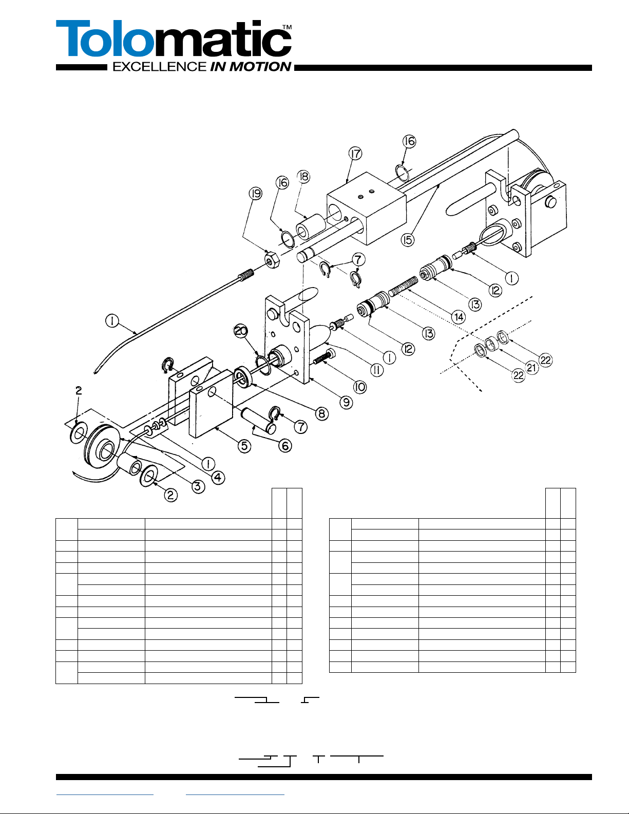
ITEM
PART NO. OR
CONFIG. CODE DESCRIPTION
TC05
TCM05
2,31. CATC05SK_ CABLE ASSEMBLY 2
CATCM05SK_ CABLE ASSEMBLY W/ MAGNET 2
2. 0100-1306 THRUST RACE 4 4
3. 1001-1055 NEEDLE BEARING 2 2
4. 1050-9005 PULLEY ASSEMBLY 2 2
5. 1085-1005 CYLINDER HEAD, SINGLE PORT 2 2
1001-1109 GLAND INSERT 2 2
6. 1001-1052 PULLEY SHAFT 2 2
7. 1001-1056 EXTERNAL RETAINING RING 8 8
38. 1085-1025 TUBE SEAL, BUNA-N MATERIAL 2 2
1085-1025 TUBE SEAL, VITON®MATERIAL 2 2
9. 1085-1050 CLAMP PLATE 2 2
10. 1085-1075 SOCKET HEAD CAP SCREW 8 8
111. RTBTC05SK_ ALUMINUM TUBE 1
RTBTCM05SK_ ALUMINUM TUBE W/ MAGNET 1
ITEM
PART NO. OR
CONFIG. CODE DESCRIPTION
TC05
TCM05
312. 1080-1020 PISTON U-CUP, BUNA-N MATERIAL 2 2
1080-1020 PISTON U-CUP, VITON®MATERIAL 2 2
13. 1085-1040 PISTON 2 2
14. 1001-1194 PISTON SPACER 1
1001-1231 PISTON SPACER WITH MAGNET 1
115. NGSTC05SK_ GUIDE SHAFT 2
NGSTCM05SK_ GUIDE SHAFT W/ MAGNET 2
16. 1001-1199 INTERNAL RETAINING RING 4 4
17. 1001-1197 BEARING BLOCK 1 1
18. 1001-1192 LINEAR BEARING 3 3
19. 1004-1188 JAM NUT 2 2
20. 1085-1018 EXTERNAL RETAINING RING 2 2
21. 1080-1012 MAGNET RING 1
22. 1085-1042 ROD, SPACER, PISTON 2
Track Cable Cylinder
TC05 1/2" Bore MODELS: TC05
TCM05
Replaced #1001-0230 & #1001-0234
Part Numbers noted for Repair Kits
and Cable Assemblies are for standard
cylinders only. Always make reference
to the complete configuration number
and stroke length of your cylinder
when ordering replacement items.
3 Repair Kit (RK) includes: Piston U-Cups, Quad Rings,
O-Rings, Cable Assembly
4 Mis for optional switch magnet, which is required for
switches to function. Since the Magnet Option adds
length to the piston and the tube length, it must be
included when ordering.
Model
Repair Kit
Magnet
4
Stroke Length
Size
___ TC M 05 SK_____
RTB TC M 05 SK21.25
__ TC M 05 SK_____
RK TC M 05 SK21.25
Tube
1 Replacement Tube (RTB) & Guide Shaft (NGS) ordering method:
EXAMPLE:
2 Repair Kit (RK) & Cable Assembly (CA) ordering method:
EXAMPLE:

Parts Sheet #1001-4009_06_TC05ps TC05 Instructions – 2
Installation
When unpacking a track cable cylinder, BE EXTRA CAREFUL NOT TO
SCRATCH OR MAR THE NYLON COVERING ON THE CABLE. The cylin-
der may be mounted by use of the bolt holes in head. When attaching
the bearing block to a driven mechanism, be sure it is in perfect align-
ment and that the load does not exceed the specifications listed in the
catalog.
Pretensioning and proof-loading instructions: All track cable cylinders
are shipped without being pretensioned. They must be tensioned after
mounting to insure the maximum service life of the unit. There are two
types of stretch in cable— constructional and elastic. The construc-
tional stretch is removed by proof-loading of the cable. The elastic
stretch is removed by proper pretensioning of the cable.
Proof-loading of cables(for cylinders without Auto Tensioners)
1. Tighten the bracket terminal lock nuts equally with a torque wrench
to torque requirements listed in Table A.
2. Let set for 30 seconds.
3. Loosen lock nuts to remove tension.(But leave them tight enough
to eliminate any slack.)
4. Follow Pretensioning Instructions.
TABLE A: TORQUE TO PROOF-LOAD THE CABLE
MODEL REQUIRED TORQUE
TC05 15 INCH-POUNDS (1.69 NEWTON-METERS)
Pretensioning of cables
1. Remove one of the guide shafts to gain access to the terminals to
adjust the cable tension.
2. Block the load some distance from the end of travel to keep the cyl-
inder from bottoming.
3. Apply pressure 15 to 20 percent higher than the actual pressure
required to move the load.
NOTE: Load pressure is defined as the actual pressure required to
move the load. When the load is stopped externally before the pis-
ton bottoms, the relief valve or regulator setting becomes the load
pressure.
When pressurized, one cable will become tight while the other
becomes slack. Manually take up the slack in the cable. Release
the pressure and block the load from the other side. Repeat the
manual adjustment on the other cable. Release pressure and
remove the blocks. Reinstall the guide shaft which had been
removed. Return the regulator to its original setting.
The cylinder is now pretensioned. Additional manual adjustment
should not be required. It is suggested however, that the cable ten-
sion be checked periodically.
Alternate Method: If the load cannot be blocked for cable preten-
sioning as stated above, tighten the bracket terminal lock nuts with
a torque wrench to total pretensioning torque as stated in Table B.
TABLE B: TORQUE FOR UNBLOCKABLE LOADS
MOD-
EL
PRETENSIONING
TORQUE +
STARTING TORQUE
OF TERMINAL NUTS =
TOTAL PRETENSION-
ING TORQUE
TC05 2.5 IN-LBS. + 10.0 IN.-LBS. = 12.5 IN.-LBS.
0.282 N-M + 1.130 N-M = 1.412 N-M
TO REBUILD THE CYLINDER
1. Remove the track cable cylinder from machinery.
2. Remove the Guide Shafts(15) then disconnect Cables(1) from
Bearing Block(17) and remove Pulleys(4) on both ends of track
cable cylinder.
3. Remove one Head(5) from track cable cylinder by removing the
four Cap Screws(10).
4. Pull Piston(13) towards the removed Cylinder Head(5) and remove
from the Tube(11).
5. Disconnect Cables(1) from Piston(13).(See Cable Assembly/
Disassembly Instructions ). Then remove the other Cylinder Head(5)
from Tube(11) and disengage Cable(1) from it.
6. Install new U-cups(12) Pistons(13).
7. See Cable Assembly/Reassembly Instructions below. Always lubri-
cate seals with oil when installing.
Drawing repeated for reference
8. Put one Cable(1) end through each Cylinder Head(5). Reattach one
head tube and connect the end of one Cable(1) to the Piston(13).
Then connect the other Cable(1) to the Piston(13).
9. Push Piston(13) back into Tube(11) by gently tucking in the
U-cup(12). Mount Cylinder Head(5) back on cylinder with the Cap
Screws(10). Replace Pulleys(4) and connect Cables(1) to Bearing
Block(17).
10. Pretension Cables(1) according to the pretensioning instructions.
11. Operate track cable cylinder back and forth by hand several times to
be sure it is properly assembled before applying pressure.
12. Reinstall track cable cylinder on machinery.
IMPORTANT NOTE: Apply(Blue) Loctite® #242 or equivalent to thread-
ed cable terminal before connecting to the piston.
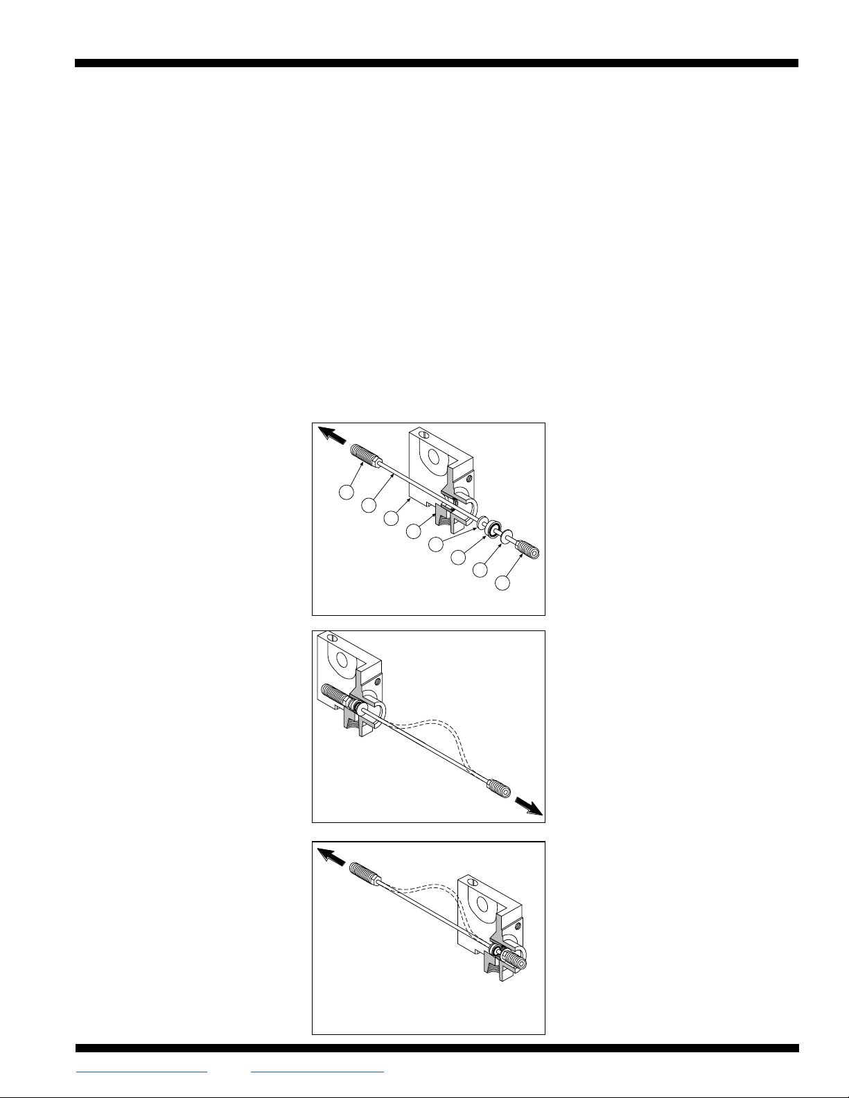
SNAP IN/OUT CABLE ASSEMBLY INSTRUCTIONS
Tolomatic cylinders with 1/2-, 3/4- and 1-inch bores are designed to
allow assembly and disassembly of Cables from the heads without the
use of tools. This eliminates the possibility of damaging the cable or
seals as well as providing for quick repair times.
Disassembly
1. Holding onto cylinder Head(6), pull Piston
Terminal(1) until bracket terminal in(8) is
against Washer(4).
2. Put a small amount of slack in Cable(7)
as shown in Figure 2.
3. Impart a “snap” action to Piston
Terminal(1).
4. With the imparting snap action, Washer(2)
will release allowing the removal of the
complete cable assembly.
Reassembly
1. Holding onto cylinder Head(6), string
Bracket Terminal(8) through Gland(5)
until Washer(4), U-cup(3) and Washer(2)
are held flush against one another by
Piston Terminal(1).
2. Put a small amount of slack in Cable(7)
as shown in Figure 3.
3. Impart a “snap” action to Bracket
Terminal(8).
4. With the snap, Washer(2) with snap into
Gland(5).
5. Move the cable in the opposite direction
as shown in Figure 3, to verify if
Washer(2) is seated in Gland(5). If not,
repeat steps 1-4.
MAINTENANCE
Keep the cylinder as clean as possible around pulleys, glands, etc.
Pneumatic service should be adequately lubricated with SAE 10 or 20
grade non-detergent oil. Pulleys have permanently lubricated bearings
and will require no maintenance. Check the cylinder’s cables periodical-
ly to help prevent premature or unexpected failures.
Your Tolomatic Cable Cylinder will give you many cycles of trouble free
service. However, should a leak occur, a rebuilding kit may be obtained
which enables you to replace all the seals in a cylinder to return it to
normal operating condition.
NOTE: Every Tolomatic Cable Cylinder has its stroke length indicated on
the identification tag shipped with the cylinder. Refer to this stroke mea-
surement when ordering replacement parts for the cylinder.
Should the tag be missing, measure the length of the cylinder including
the heads at both ends. If there are no switches present on the cylinder,
check the piston for a magnet to see if it is a Reed Switch model. If it is,
consult the Tolomatic Cable Cylinder catalog dimensional drawings for
“stroke-plus” length and subtract 1.62 inches for cylinders with 1/2-
inch 3/4-inch and 1-inch bores and .375 inches
for all larger bore Reed Switch models to deter-
mine the stroke length.
Parts Sheet #1001-4009_06_TC05ps TC05 Instructions – 3
8
7
6
5
4
3
2
1
FIGURE 1.
FIGURE 2.
FIGURE 3.
All brand and product names are trademarks or registered trademarks of their
respective owners. Information in this document is believed accurate at time of print-
ing. However, Tolomatic assumes no responsibility for its use or for any errors that
may appear in this document. Tolomatic reserves the right to change the design or
operation of the equipment described herein and any associated motion products
without notice. Information in this document is subject to change without notice.
Visit www.tolomatic.com for the most up-to-date technical information
3800 County Road 116, Hamel, MN 55340 USA
http://www.Tolomatic.com • Email: Help@Tolomatic.com
Phone: (763) 478-8000 • Fax: (763) 478-8080 • Toll Free: 1-800-328-2174
© 2022 Tolomatic 202201311120
Parts Sheet #1001-4009_06_TC05ps TC05 Switches– 4
REED SWITCH FORM A
LABEL COLOR: RED
10VA MAX. 200 VDC
500MA MAX. CURRENT
Universal Switch Wiring Diagrams and Label Color Coding
TRIAC SWITCH
LABEL COLOR: BLUE
MAX. 1AMP. CONT.
CURRENT @ 86°F
MAX. .5AMP. CONT.
CURRENT @ 140°F
PEAK SURGE CURRENT 10AMP.
QUICK-DISCONNECT
(APPLIES TO ALL SWITCH TYPES)
An Important Note Regarding Field
Retrofit of Quick-Disconnect Couplers:
If replacing a Quick-Disconnect switch
manufactured before
7-1-97 it will also be necessary to
replace or rewire the female-end cou-
pler with the in-line splice
Female Connector 5M
For complete Reed and TRIAC Switch Performance Data, refer to the
Tolomatic Pneumatic Products Catalog.
Loctite® is a registered trademark of the Loctite Corporation, www.loctite.com
Viton® is a registered trademark of the E.I. Du Pont de Newmours Co., www.dupont.com
NOTE: The side of the switch with the
groove indicates the sensing surface.
This must face toward the magnet.
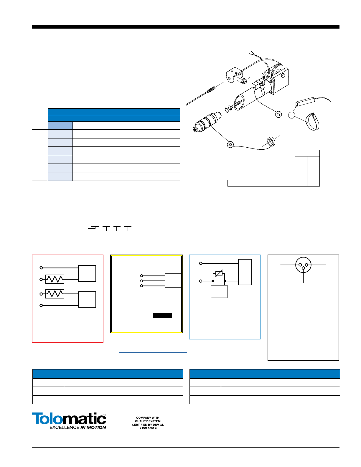
DESCRIPTION
QUANTITY
ITEM PART NO.
TC05
TCM05
22. 1075-1019 MAGNET 1
REED SWITCHES
NOTE: Form A Reed Switches should not be used in TTL logic circuits. A voltage
drop caused by the L.E.D. indicator will result.For applications where TTL circuits
are used, please contact Tolomatic.
WARNING: An ohmmeter is recommended for testing Reed Switches. NEVER use
an incandescent light bulb as a high current rush may damage the switch.
Reed and TRIAC switches are only recommended for signalling position, not directly
powering soleniods. For shifting a solenoid, a relay or resistor is recommended
between it and the switch. Switch ratings must not be exceeded at any time
CONFIG. CODE ORDERING
MOUNTING HARDWARE & FE CONN. INCLUDED
ITEM
CODE
DESCRIPTION
19. BT SWITCH KIT, REED, FORM C, 5M
BM SWITCH KIT, REED, FORM C, QD MALE CONN.
RT SWITCH KIT, REED, FORM A, 5M
RM SWITCH KIT, REED, FORM A, QD MALE CONN.
CT SWITCH KIT, TRIAC, 5M
CM SWITCH KIT, TRIAC, QD MALE CONN.
NOTE: When ordered female connector & all mounting hardware is included
19
To Order Retrofit Kits
All Switch Kits come with 1 switch and mounting hardware.
Model
Switch Kit
Size Switch Type Code
SW TC __ __
SW TC 60 RT
Retrofit ordering method:
EXAMPLE:
REED SWITCH FORM C
LABEL COLOR: YELLOW
120 VDC/120 VAC MAX.
250MA MAX. CURRENT
AC
COM
LOAD
INPUT
BROWN
BROWNBLUE
BLACK
BLUE
MOV
TRACC
SWITCH
120/VAC
MAX.
REED
SWITCH
BLUE
NORMALLY OPEN
BLACK
NORMALLY CLOSED
BROWN
BROWN
BLUE
BROWN
BLUE
COMMON
REED
SWITCH
REED
SWITCH
(-)
(-)
(+)
(+) (+)
(+)
(-)
(-)
LOAD
LOAD
OR
SWITCH TYPE CODE
BT FORM C REED SWITCH WITH 5-METER LEAD
BM FORM C REED SWITCH WITH 5-METER LEAD AND QD
RT FORM A REED SWITCH WITH 5-METER LEAD
SWITCH TYPE CODE
RM FORM A REED SWITCH WITH 5-METER LEAD AND QD
CT TRIAC SWITCH WITH 5-METER LEAD
CM TRIAC SWITCH WITH 5-METER LEAD AND QD
This manual suits for next models
1
Other Tolomatic Cables And Connectors manuals


