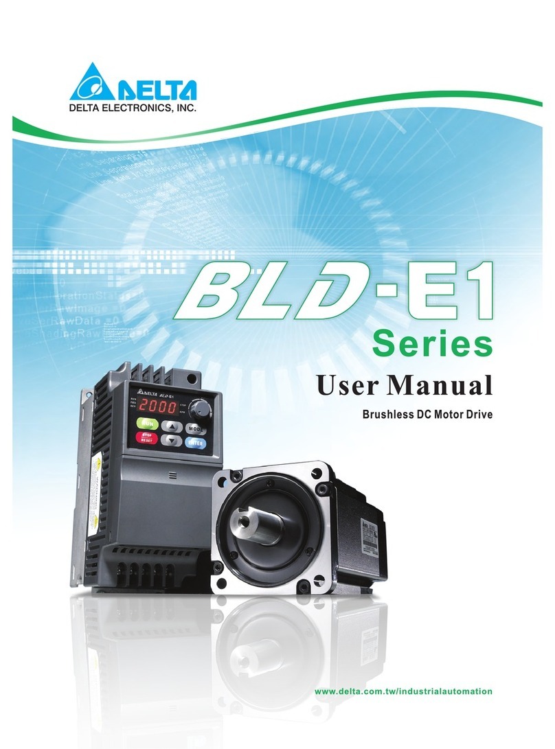
Tolomatic STAC6 User manual

STAC6 Drives and
Microstepping Motors
LINEAR SOLUTIONS MADE EASY
LINEAR SOLUTIONS MADE EASY
User Manual
STAC6 DRIVES AND
MICROSTEPPING MOTORS
are DISCONTINUED.
Replacements are not
available. For legacy
STAC6 drives and
Microstepping Motors use
this manual for reference
only.
3600-4645_02_AMPSTEP-OBS

© 2022 Tolomatic
Tolomatic, Incorporated. All rights reserved.
Tolomatic and Excellence In Motion are registered
trademarks of Tolomatic Incorporated. All other
products or brand names are trademarks of their
respective holders.
202204130849

STAC6 Drives and Microstepping Motors: User Manual (Discontinued Product)
• i •
Contents
Contents............................................................................................................... i
List of Figures.................................................................................................ii -iii
Overview
Technical Specifications .................................................................................iv - vi
Control Options...................................................................................................vii
Block Diagram ...................................................................................................viii
Drive Dimensions ................................................................................................ ix
Chapter 1: Hardware
Safety Instructions.................................................................................... 1.1 - 1.2
Introduction.......................................................................................................1.3
Getting Started .................................................................................................1.4
Error Codes / Status LED..................................................................................1.5
RS 232 Communications ..................................................................................1.6
RS 485 Communications ......................................................................... 1.7 - 1.8
RS 422 Wiring............................................................................................1.9
RS 485 Wiring..........................................................................................1.10
Connecting AC Power.....................................................................................1.11
Connecting the Motor .....................................................................................1.12
Connecting the Encoder ...................................................................... 1.13 - 1.15
Connecting to In/Out 1....................................................................................1.16
Wiring Digital Inputs to In/Out 1 .................................................... 1.16 - 1.24
Wiring Digital Outputs to In/Out 1 ................................................. 1.25 - 1.26
Wiring Analog Signals to In/Out 1 ................................................. 1.27 - 1.28
Connecting to In/Out 2....................................................................................1.29
Wiring Digital Inputs to In/Out 2 .................................................... 1.29 - 1.32
Wiring Digital Outputs to In/Out 2 ................................................. 1.33 - 1.35
Wiring Analog Signals to In/Out 2 ................................................. 1.36 - 1.37
Regeneration Clamp ............................................................................ 1.38 - 1.39
Chapter 2: Recommended Motors
General Motor Data...........................................................................................2.1
Size 23 Motors..................................................................................................2.1
Size 34 Motors..................................................................................................2.2
Rec. Motor Dimensions............................................................................ 2.4 - 2.5
Chapter 3: Configuration
STAC6 Configurator Software .................................................................. 3.1 - 3.3
Configuring the Motor .............................................................................. 3.4 - 3.7
Input and Outputs.................................................................................. 3.8 - 3.10
Status Monitor ................................................................................................3.11
Chapter 4: Standard Accessories & Options
Breakout Box for In/Out Connectors .................................................................4.1
HUB [SiNET™ HUB 444] Multi-Axis Motion Hub with I/O ............................. 4.2 - 4.13
Chapter 5: Contacting Tolomatic....................................................................5.1

STAC6 Drives and Microstepping Motors: User Manual (Discontinued Product)
• ii •
Figure Description Page
1 DS[STAC6-S] and SI[STAC6-Si] Block Diagram ............................................................viii
2 DS[STAC6-S] and SI[STAC6-Si] Drive Mounting Dimensions ...........................................ix
1.1 STAC6 Applied Motion Products (Motor Control) ..........................................................1.3
1.2 STAC6 Error Codes....................................................................................................1.5
1.3 422 Wiring................................................................................................................1.9
1.4 485 Wiring..............................................................................................................1.10
1.5 AC Connection ........................................................................................................1.11
1.6 Motor Cable Wiring..................................................................................................1.12
1.7 HD 15 Pinouts.........................................................................................................1.13
1.8 Encoder Dialog........................................................................................................1.14
1.9 Connections In/Out 1...............................................................................................1.16
1.10 Step Source............................................................................................................1.17
1.11 Step Sink................................................................................................................1.17
1.12 Step Differential ......................................................................................................1.17
1.13 Connecting the Master Encoder ...............................................................................1.18
1.14 Connecting to PLC with Sourcing (PNP) Outputs........................................................1.18
1.15 PLC Sinking ............................................................................................................1.19
1.16 Mechanical Switches...............................................................................................1.19
1.17 Inside Inputs ...........................................................................................................1.20
1.18 INP Relay................................................................................................................1.21
1.19 Si1 .........................................................................................................................1.21
1.20 INP NPN In/Out 1 ....................................................................................................1.21
1.21 INP PNP In/Out 1.....................................................................................................1.21
1.22 STAC6 Limit Input Diagram......................................................................................1.22
1.23 Mechanical Limit Switch..........................................................................................1.23
1.24 NPN Limit Sensor....................................................................................................1.23
1.25 PNP Limit Sensor ....................................................................................................1.24
1.26 Connections In/Out 1...............................................................................................1.25
1.27 STAC6 Outputs .......................................................................................................1.25
1.28 STAC6 Outsinking ...................................................................................................1.26
1.29 STAC6 Relay...........................................................................................................1.26
1.30 Connections In/Out..................................................................................................1.27
1.31 Analog Single Ended Signal .....................................................................................1.27
1.32 Analog Pot..............................................................................................................1.28
1.33 In/Out 2 Connections...............................................................................................1.29
1.34 Inputs SI[STAC6-Si] ................................................................................................1.30
1.35 Switch In/Out 2.......................................................................................................1.31
1.36 Step Source............................................................................................................1.31
1.37 NPN Proximity In/Out 2............................................................................................1.32
1.38 PNP Proximity In/Out 2 ............................................................................................1.32
1.39 In/Out 2 Connections...............................................................................................1.33
1.40 Outputs SI[STAC6-Si] ..............................................................................................1.34
(Continued)
List of Figures

STAC6 Drives and Microstepping Motors: User Manual (Discontinued Product)
• iii •
Figure Description .....................................................................................Page
1.41 Sourcing Out...........................................................................................................1.34
1.42 SI[STAC6-Si] Out Sinking ........................................................................................1.35
1.43 SI[STAC6-Si] Relay .................................................................................................1.35
1.44 In/Out 2 Connections...............................................................................................1.36
1.45 Connecting an Analog Input to an Active Signal .........................................................1.37
1.46 STAC6 Internal Regen..............................................................................................1.38
1.47 Regen Resistor Connection ......................................................................................1.39
1.48 STAC6 External Regen.............................................................................................1.39
2.1 General Motor Data Table...........................................................................................2.1
2.2 Size 23 Motors..........................................................................................................2.1
2.3 HT 23 Torque Curves.................................................................................................2.2
2.4 Size 34 Motors..........................................................................................................2.2
2.5 HT 34 Torque Curves.................................................................................................2.3
2.6 HT23 Step Motors.....................................................................................................2.4
2.7 HT34 Step Motors.....................................................................................................2.5
3.1 STAC6 Configurator...................................................................................................3.1
3.2 Motor Dialog .............................................................................................................3.4
3.3 Add New Motor Dialog...............................................................................................3.6
3.4 Lead Angle Graph......................................................................................................3.7
3.5 I/O Dialog .................................................................................................................3.8
3.6 Status Monitor ........................................................................................................3.11
4.1 HUB [SiNET™ HUB 444] .........................................................................................4.2
4.2 HUB [SiNET™ HUB 444] Features............................................................................4.5
4.3 Connecting the HUB [SiNET™ HUB 444] ..................................................................4.6
4.4 Programmable Input Circuit Schematic Diagram..........................................................4.9
4.5 Connecting an Si Drive ............................................................................................4.10
4.6 Connecting an NPN Type Prox. Sensor ......................................................................4.10
4.7 Connecting an PNP Type Prox. Sensor ......................................................................4.10
4.8 Output Circuit Schematic Diagram............................................................................4.11
4.9 Sinking Output ........................................................................................................4.11
4.10 Sourcing Output......................................................................................................4.11
4.11 Driving a Relay........................................................................................................4.12
4.12 Mechanical Outline..................................................................................................4.12
4.13 Pin Assignments .....................................................................................................4.13
LIST OF FIGURES

STAC6 Drives and Microstepping Motors: User Manual (Discontinued Product)
• iv •
Technical Specifications
POWER AMPLIFIER SECTION: DS[STAC6-S], SI[STAC6-Si]
Amplifier Type MOSFET, Dual H-Bridge, 4 Quadrant
Current Control 4 state PWM at 20 Khz
Output Current 0.5 — 6.0 in 0.01 amp increments
Power Supply Line Operated Nominal 120 VAC, 50/60 Hz
DC Bus Voltage Nominal 165 VDC
AC Input Voltage 94—135VAC, 50/60Hz
Protection Over-Voltage, Under voltage, Over-Temp, External Output Shorts (Phase
to-Phase, Phase-to-Ground), Inter Amplifier Shorts
Idle Current Reduction Reduction to any integer percent of full-current after delay selectable in
milliseconds
POWER AMPLIFIER SECTION: DS[STAC6-S-220], SI[STAC6-Si-220]
Amplifier Type MOSFET , Dual H-Bridge, 4 Quadrant
Current Control 4 state PWM at 20 Khz
Output Current 0.5 — 3.0 in 0.01 amp increments
Power Supply Line Operated Nominal 120-240 VAC, 50/60 Hz
DC Bus Voltage Nominal 330 VDC (at 240 VAC line input)
AC Input Voltage 94—265VAC, 50/60Hz
Protection Over-Voltage, Under voltage, Over-Temp, External
Output Shorts (Phase to-Phase, Phase-to-Ground),
Inter Amplifier Shorts
Overview

STAC6 Drives and Microstepping Motors: User Manual (Discontinued Product)
• v •
OVERVIEW
Idle Current Reduction Reduction to any integer percent of full-current after delay
selectable in milliseconds.
CONTROLLER SECTION
Non-Volatile Storage Configurations are saved in FLASH memory
aboard the DSP.
Mode of Operation Step & Direction, CW/CCW, Encoder Following, Joystick:
Step & Direction Inputs Optically Isolated: 5-12 Volt. Minimum pulse width = 200 ns.
Maximum pulse frequency = 2 MHz
Speed Range Depends upon selected resolution. Amplifier is
suitable for speeds up to 50 rps
Analog Input Range Software selectable: 0-5V, ±5V, 0-10V, ±10V
Analog Input Resolution 12 bits (with ±10V signal range)
11 bits (with 0-10V or ±5V signal range)
10 bits (with 0-5V signal range)
Microstep Resolution Software selectable from 200 to 50800 steps/rev in
increments of 200 steps/rev
Anti-Resonance Raises the system damping ratio to —0.3-to-0.5.
Eliminates midrange instability and allows stable
operation to 50 rps.
Waveform Allows for fine adjustment of phase current waveform harmonic
content to reduce low-speed torque ripple in the range
0.25 to 1.5 rps
Auto Setup Measures motor parameters and configures tuning and observer
parameters
Self Test Identifies the presence of an encoder and determines resolution.
Diagnoses miswires and open phases

STAC6 Drives and Microstepping Motors: User Manual (Discontinued Product)
• vi •
OVERVIEW
Microstep Emulation Performs low resolution stepping by synthesizing coarse steps from fine
microsteps.
Dynamic Smoothing Software configurable filtering (4th order, elliptic) for
use in removing spectral components from the
command sequence. Reduces jerk and excitation of
extraneous system resonances.
Encoder Option Employs encoder (hi or low resolution) to provide stall
detection, stall prevention and perform position
verification and maintenance.
Interface RS-232 and RS-485 Bus
Encoder Differential line receivers suitable for 200 KHz or greater
Ambient Temperature 0 to 55°C (32 - 158°F)
Humidity 90% non-condensing

STAC6 Drives and Microstepping Motors: User Manual (Discontinued Product)
• vii •
OVERVIEW
Motion Control Options
!
DS[ ]
• Basic drive; analog, digital and host command input.
• Pulse & direction with electronic gearing.
• Encoder following with electronic gearing.
• CW and CCW pulse.
• Multi-axis Si programming if used with a HUB [SiNET™ HUB 444].
• "Host" commands for real time control from a host PC or
PLC using RS-232 or RS-485 serial communication.
!
SI[ ]
• SI[STAC6-Si] can be programmed for stand-alone operation with
the easy to use Si Programmer™ Windows software with integrated
tuning (software and programming cable included).
• Graphical point and click format combines motion, I/O,
and operator interface functionality for simple machine
sequencing.
• Easily integrates with other devices on the machine
(Sensors, PLCs etc).

STAC6 Drives and Microstepping Motors: User Manual (Discontinued Product)
• viii •
OVERVIEW
Figure 1: DS[STAC6-S], SI[STAC6-Si] Block Diagram

STAC6 Drives and Microstepping Motors: User Manual (Discontinued Product)
• ix •
OVERVIEW
Figure 2: DS[STAC6-S], SI[STAC6-Si] Drive Mounting Dimensions

1
STAC6 Drives and Microstepping Motors: User Manual (Discontinued Product)
• 1.1 •
Safety Instructions
Only qualified personnel are permitted to transport, assemble,
commission, and maintain this equipment. Properly qualified personnel
are persons who are familiar with the transport, assembly, installation,
commissioning and operation of motors, and who have the
appropriate qualifications for their jobs. The qualified personnel must
know and observe the following standards and regulations:
IEC 364 resp. CENELEC HD 384 or DIN VDE 0100
IEC report 664 or DIN VDE 0110
National regulations for safety and accident prevention or VBG 4
To minimize the risk of potential safety problems, follow all applicable
local and national codes that regulate the installation
and operation of your equipment. Since codes vary from area to
area it is the users responsibility to determine which codes should be
followed, and to verify that the equipment, installation, and operation
are in compliance with the latest revision of these codes.
Equipment damage or serious injury to personnel can result from the
failure to follow all applicable codes and standards. We do not
guarantee the products described in this publication are suitable for
your particular application, nor do we assume any responsibility for
your product design, installation, or operation.
Read all available documentation before assembly and commissioning.
Incorrect handling of products in this manual can result in injury and
damage to persons and machinery. Strictly adhere to the
technical information on the installation requirements.
It is vital to ensure that all system components are connected to earth
ground. Electrical safety is impossible without a low-resistance earth
connection.
!
The STAC6 contains electrostatically sensitive components that can
Hardware

STAC6 Drives and Microstepping Motors: User Manual (Discontinued Product)
• 1.2 •
1: HARDWARE
be damaged by incorrect handling. Discharge yourself before touching
the product. Avoid contact with high insulating materials (artificial
fabrics, plastic film, etc.). Place the product on a conductive surface.
During operation keep all covers and cabinet doors shut. Otherwise,
there are deadly hazards that could possibly cause severe bodily
damage or damage to the product.
In operation, depending on the degree of enclosure protection, the
product can have bare components that are live or have hot surfaces.
Control and power cables can carry a high voltage
even when the motor is not rotating.
Never pull out or plug in the product while the system is live. There is a
danger of electric arcing and danger to persons and contacts.
After powering down the product, wait at least ten minutes before
touching live sections of the equipment or undoing connections (e.g.,
contacts, screwed connections). Capacitors can store dangerous
voltages for long periods of time after power has been switched off. To
be safe, measure the contact points with a meter before touching.
Be alert to the potential for personal injury. Follow the recommended
precautions and safe operating practices.
Safety notices in this manual provide important information. Read and
be familiar with these instructions before attempting installation,
operation, or maintenance. The purpose of this section is to alert users
to possible safety hazards associated with this equipment and the
precautions that need to be taken to reduce the risk of personal injury
and damage to the equipment.
Failure to observe these precautions could result in serious bodily injury,
damage to the equipment,or operational difficulty.

STAC6 Drives and Microstepping Motors: User Manual (Discontinued Product)
• 1.3 •
1: HARDWARE
Introduction
Figure 1.1: STAC6 Applied Motion Products (Motor Control)
Thank you for selecting an Applied Motion Products motor control from
Tolomatic. We are committed to making your motion control project
successful.
If there’s anything we can do to help you service or troubleshoot your
system. Contact our technical support department at
(800) 325-2174 or you can reach us by fax at (763) 478-8080.

STAC6 Drives and Microstepping Motors: User Manual (Discontinued Product)
• 1.4 •
1: HARDWARE
Getting Started
For all STAC6 Drive models, you must have the following:
• 120VAC or 220VAC single phase power
• A compatible stepper motor
• A small flat blade screwdriver for tightening the connectors (included).
• A personal computer running Microsoft Windows 98, NT, Me, 2000
or XP.
• The "Software, Manuals & More" CD that was included with your
STAC6 Stepper drive
• A programming cable (included)
Familiarize yourself with the drive and the software before deploying
the system in your application.
Recommended Procedures:
1. Install the Configurator™ software from the CD.
2. Launch the software by clicking Start...Programs...Applied Motion
Products...Configurator.
3. Connect the drive to your PC using the programming cable supplied.
4. Connect the drive to the AC power source (may be switched).
5. Connect the drive to the motor.
6. Apply power to the drive.
7. Follow the instructions in the Configurator™ help screens.
(On the CD)

STAC6 Drives and Microstepping Motors: User Manual (Discontinued Product)
• 1.5 •
1: HARDWARE
Error Codes / Status LED
The STAC6 includes a bi-color (red/green) LED to indicate status.
Normal status is indicated by a solid green LED. If the LED changes to
red, an error has occurred. The errors are indicated by combinations of
red and green "flashes" as follows:
Figure 1.2: STAC6 Error Codes

STAC6 Drives and Microstepping Motors: User Manual (Discontinued Product)
• 1.6 •
1: HARDWARE
RS 232 Communications
CONNECTING TO THE PC USING RS - 232
Locate your computer within 6 feet of the STAC6 Stepper drive.
The drive is shipped with a black adapter plug. A telephone style
jack is at one end and a larger 9-pin connector at the other. Plug
the large end into the COM1 serial port of your PC. Secure the
adapter with the screws on the sides. If the COM1 port on your PC
is already in use, the COM2 port may be used for the drive. On
some PCs, COM2 will have a 25 pin connector that does not fit the
black adapter plug. If this is the case, purchase a 25-to-9 pin serial
adapter sold at local computer stores.
The drive is also shipped with a 7 foot telephone line cord. Plug one
end into the black adapter plug attached to your PC, and the other
end into the RS-232 jack on the drive. If the drive needs to be
located farther from the PC, replace the 7 foot phone cord with a
longer one. Do not use cords in excess of 50 feet.
Never connect a STAC6 drive to a telephone circuit. It uses the
same connectors and cords as telephones and modems, but the
voltages are not compatible.

STAC6 Drives and Microstepping Motors: User Manual (Discontinued Product)
• 1.7 •
1: HARDWARE
RS 485 and RS 422 Communications
CONNECTING TO THE PC USING RS-485
RS-485/422 allows connection of more than one drive to a single
host PC, PLC or other computer. It also accommodates a longer
cable (more than 1000 feet) for devices that have a RS-485/422 port.
A SHORT TUTORIAL ON RS-485 & RS-422
RS-485 in the strictest definition is a "2-wire" interface that
allows multi-node connections limited to "Half-duplex" serial
communications. Up to 32 nodes that both transmit and receive
can be connected to the network. RS-422 in the strictest definition
is a "4-wire" point-to-point connection that allows "Full-duplex"
serial communications when connected to a single node. RS-422
has one node that is the driver or transmitter and up to 10 nodes
that are receivers. RS-422 was not designed for a true multi-node
network.
2- wire interfaces require a network node, master or slave, must be
able to tristate its transmitter to allow other nodes to use the
network when required. For high speed baud rates this must be
done very quickly to avoid communications collisions.
4-wire interfaces can go beyond the simple point-to-point and
accommodate multi-node networks if the slave node is capable of
tri-stating their transmitters as required in the 2-wire networks.
Some RS-485 devices are setup to do this and can be used in a
4-wire configuration.
On the AMP Servo drives, the RS-485 can be implemented
with either "2-wire" or "4-wire" interfaces. In both cases,
communications are still limited to "Half-duplex" because of
the nature of the serial communications protocols used. 4-wire
implementations can sometimes be easier due to the greater
number of Host RS-232 to RS-485 adapters that support the 4-wire
interface. 2-wire implementations may require special Host adapters
that support

STAC6 Drives and Microstepping Motors: User Manual (Discontinued Product)
• 1.8 •
1: HARDWARE
"Auto enable" of the adapter transmitter. Host adapters are required
as PC software typically doesn’t support tri-stating the output of the
serial adapters.
In both 2-wire and 4-wire systems one extra wire is always required
to connect the "Grounds" of all the nodes on the network. Even
though 2-wire and 4-wire systems send differentially, a command
ground connection is absolutely required.
In addition, proper cable shielding is a must. High voltage, high
frequency, high current signals that are present on servo motor
cables can emit a significant amount of electrical interference.
Without proper shielding these signals can disrupt even "noise
tolerant" differential line drivers.
4-Wire RS-485-422 Network
The RS485 implementation is a 4-wire multi-drop network with
separate transmit and receive wires. One pair of wires connects
from the host computer’s TX+ and TX- signals to each of the drive’s
RX+ and RX- terminals. Another pair connects the TX+ and TX-
drive terminals to the host computer’s RX+ and RX- signals. A
common ground terminal is provided on each drive and can be
used to keep all drives at the same ground potential. This terminal
connects internally to the DC power supply return (V-), so if all the
drives on the RS485 network are powered from the same supply, it
is not necessary to connect the logic grounds. Connection of one
drive’s GND terminal to the host computer ground is still required.
Before wiring the entire system, connect each drive individually to
the host computer so a unique address can be assigned to each
drive. Proceed as follows: (Also see figure below)
1. Connect the drive TX+ to the PC’s RX+ terminal.
2. Connect the drive TX- to PC RX-.
3. Connect RX+ to TX+.
4. Connect RX- to TX-.
5. Connect GND to GND.
Getting and Connecting a RS485 4-wire adapter to your

STAC6 Drives and Microstepping Motors: User Manual (Discontinued Product)
• 1.9 •
1: HARDWARE
PC
A 25-pin serial port is recommended. The Jameco Electronics (800-
831-4242) Model 1117701 is a good choice. If a 9-pin serial port is on
your PC, a Jameco cable Model 31721 is also required.
Connect as follows:
adapter drive
1 RX+
2 RX-
3 TX-
4 TX+
Set the switches for DCE and TxON,RxON. Plug in the DC power
adapter that comes with the unit.
Figure 1.3: RS - 422 Wiring
The drive can also be connected to the Host computer using only a
2-wire interface. In this case, first connect the TX+ to the RX+ and the
TX- to the RX- on the servo drives before connecting to the Host
adapter. Usually RS-485 2-wire interfaces are labeled "A" & "B".
Getting and Connecting a RS485 2-wire adapter to your PC
The RS485 2-wire adapter (Model 485-25E) from Integrity Instruments
(800-450-2001) is recommended.
adapter drive
B TX+/RX+
A TX-/RX-
Table of contents
Popular Engine manuals by other brands

SEW-Eurodrive
SEW-Eurodrive MOVIMOT MM..D Series operating instructions
Vanguard
Vanguard Series 432447 Operating and maintenance instructions
AutomationDirect
AutomationDirect IronHorse HGR-37-005-A user manual
BIG TREE TECH
BIG TREE TECH TMC2209-V1.2 manual

Oriental motor
Oriental motor BLM230 operating manual

Oriental motor
Oriental motor World K Series operating manual

AOK
AOK A M25 PLUS L USB manual
woodmizer
woodmizer D42 Safety, Operation, Maintenance & Parts Manual
Delta
Delta C2000 Series Product application

Oriental motor
Oriental motor BMU Series quick start guide

Oriental motor
Oriental motor PK Series operating manual
Tecnoautomazione
Tecnoautomazione GPS Series Instructions and warnings
