manuals.online logo
Brands
  1. Home
  2. •
  3. Brands
  4. •
  5. Oriental motor
  6. •
  7. Engine
  8. •
  9. Oriental motor BLM230 User manual

Oriental motor BLM230 User manual

1
Introduction
■
■Before using the motor
Only qualied and educated personnel should work with the product.
Use the product correctly after thoroughly reading the section "Safety
precautions." Should you require the inspection or repair of internal parts,
contact the Oriental Motor oce where you purchased the product.
The product described in this manual has been designed and manufactured to
be incorporated in general industrial equipment.
Do not use for any other purpose. Oriental Motor Co., Ltd. is not responsible for
any damage caused through failure to observe this warning.
■
■Related operating manuals
Operating manuals for this product are listed below.
Operating manuals are not included with the product. Download from Oriental
Motor Website Download Page or contact your nearest Oriental Motor sales
oce.
Operating manual name
Motor BLM Motor Cable Type OPERATING MANUAL (this document)
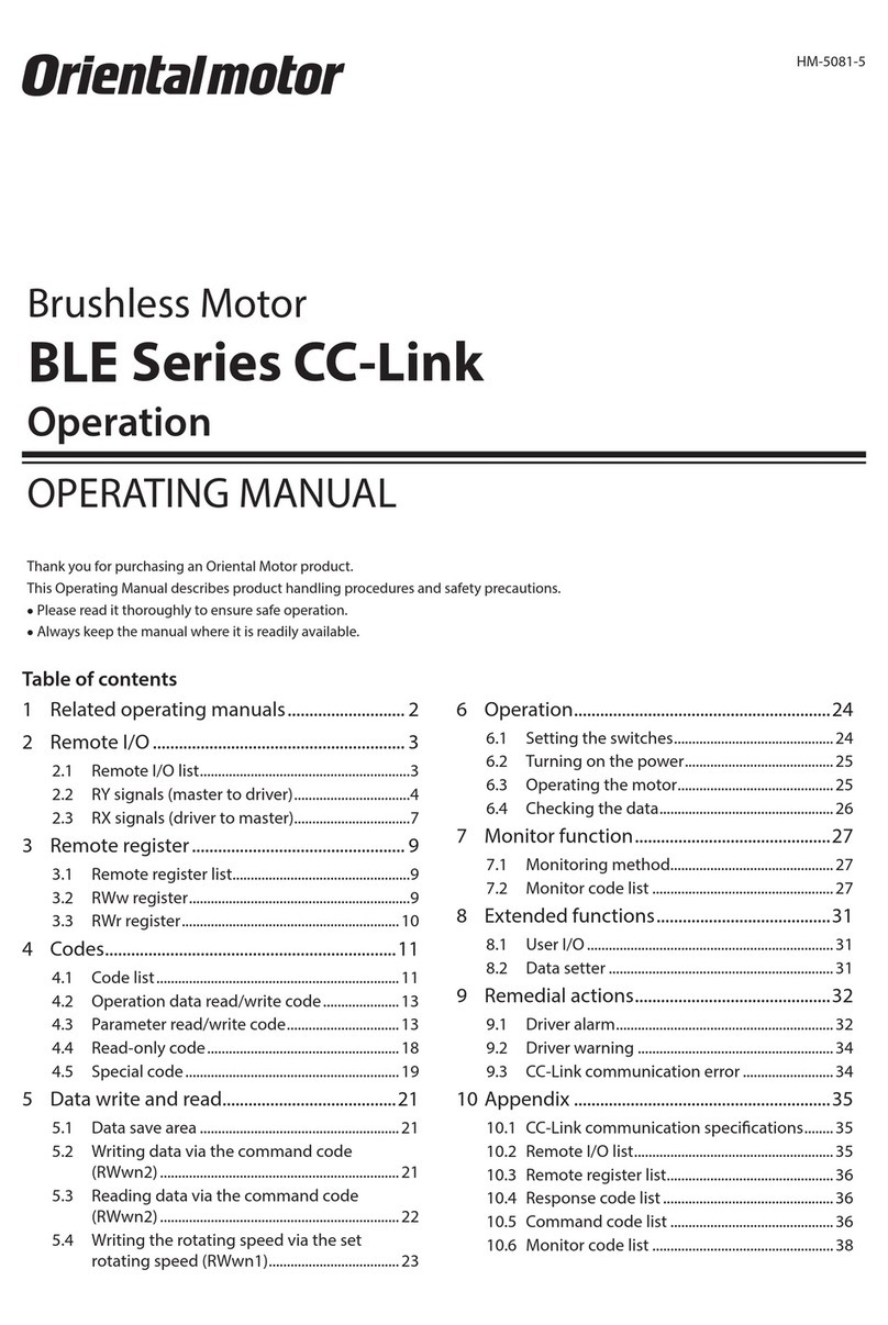
Driver BMU Series OPERATING MANUAL
Refer to the operating manual of the driver for details about connections and
operations.
Safety precautions
The precautions described below are intended to prevent danger or injury to
the user and other personnel through safe, correct use of the product. Please
read and understand these precautions thoroughly before using the product.
Handling the product without observing the
instructions that accompany a“WARNING” symbol
may result in serious injury or death.
Handling the product without observing the
instructions that accompany a“CAUTION”symbol
may result in injury or property damage.
Note
The items under this heading contain important handling
instructions that the user should observe to ensure safe
use of the product.
Description
of graphic
symbols
: Indicates "prohibited" actions that must not be performed.
: Indicates "compulsory" actions that must be performed.
•Do not use the product in explosive or corrosive environments, in the
presence of ammable gases, in places subjected to splashing water, or
near combustibles. Doing so may result in re, electric shock or injury.
•Do not transport, install, connect or inspect the product while the
power is supplied. Always turn o the power before carrying out these
operations. Electric shock or damage to equipment may result.
•Do not use a motor in a vertical application. If the driver’s protection
function is activated, the motor will stop and the moving part of the
equipment will drop, thereby causing injury or equipment damage.
•Do not machine or modify the cable. Doing so may result in re, electric
shock, or damage to equipment.
•Do not forcibly bend, pull or pinch the cable. Doing so may result in re,
electric shock, or damage to equipment.
•Do not touch the motor or driver when conducting the insulation
resistance measurement or dielectric strength test. Accidental contact
may result in electric shock.
•Do not disassemble or modify the motor. This may result in electric
shock, injury or damage to equipment. Refer all such internal inspections
and repairs to the branch or sales oce from which you purchased the
product.
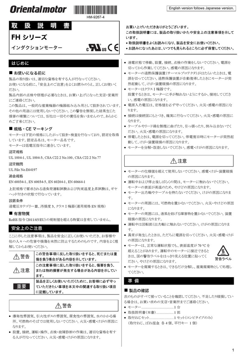
HM-5226-3
OPERATING MANUAL Thank you for purchasing an Oriental Motor product.
This Operating Manual describes product handling procedures and safety
precautions.
•Please read it thoroughly to ensure safe operation.
•Always keep the manual where it is readily available.
Brushless Motor
BLM Motor Cable Type
•Only qualied and educated personnel should be allowed to perform
installation, connection, operation and inspection/troubleshooting of the
product. Handling by unqualied and uneducated personnel may result
in re, electric shock, injury, or damage to equipment.
•The motor is ClassⅠequipment. Install the motor so as to avoid contact
with hands, or ground it to prevent the risk of electric shock.
•Use a motor and driver only in the specied combination. Failure to do so
may result in re, electric shock, or damage to equipment.
•Always turn o the power before performing maintenance or inspection.
Failure to do so may result in electric shock.
•Do not use the motor beyond the specications. Doing so may result in
re, electric shock, injury or damage to equipment.
•Do not touch the motor while operating or immediately after stopping.
The surface of the motor is hot and it may cause a skin burn(s).
•Do not leave anything around the motor that would obstruct ventilation.
Doing so may result in damage to equipment.
•Do not lift up the product by holding the output shaft or the cable. Doing
so may result in injury.
•Do not touch the motor output shaft (end or pinion) with bare hands.
Doing so may cause injury.
•When assembling the motor with the gearhead, exercise caution not to
pinch your ngers or other parts of your body between the motor and
gearhead. Injury may result.
•When installing the motor in equipment, exercise caution not to pinch
your ngers or other parts of your body between the equipment and
motor. Injury may result.
•Do not touch the rotating part (output shaft) while operating the motor.
Doing so may cause injury.
•Securely install the motor to the mounting plate. Inappropriate installation
may cause the motor to detach and fall, resulting in injury or damage to
equipment.
•Provide a cover over the rotating part (output shaft). Failure to do so may
result in injury.
•Securely install a load on the output shaft. Inappropriate installation may
result in injury.
•Be sure to ground the motor and driver to prevent them from being
damaged by static electricity. Failure to do so may result in re or damage
to equipment.
•The motor surface temperature may exceed 70 °C (158 °F)
even under normal operating conditions. If the operator
is allowed to approach the motor in operation, attach a
warning label in a conspicuous position as shown in the
gure. Failure to do so may result in a skin burn(s). Warning label
•Dispose the product correctly in accordance with laws and regulations, or
instructions of local governments.
Precautions for use
Be sure to match the motor output power with the driver output power.
zConnecting the motor and driver
Use an accessory connection cable (sold separately) when extending the wiring
distance between the motor and the driver.
zGrease measures
On rare occasions, grease may ooze out from the gearhead. If there is concern
over possible environmental damage resulting from the leakage of grease,
check for grease stains during regular inspections. Alternatively, install an oil pan
or other device to prevent leakage from causing further damage. Oil leakage
may lead to problems in the customer’s equipment or products.
zCaution when using under low temperature environment
When an ambient temperature is low, since the load torque may increase by the
oil seal or viscosity increment of grease used in the gearhead, the output torque
may decrease or an overload alarm may generate. However, as time passes, the
oil seal or grease is warmed up, and the motor can be driven without generating
an overload alarm.
2
zDo not conduct the insulation resistance measurement or dielectric
strength test with the motor and driver connected
Conducting the insulation resistance measurement or dielectric strength test
with the motor and driver connected may result in damage to the product.
zRotation direction of gearhead output shaft
In the case of the combination type-parallel shaft gearhead, the rotation
direction of the gearhead output shaft may dier from that of the motor output
shaft depending on the gear ratio of the gearhead.
Gear ratio Rotation direction of gearhead output shaft
5, 10, 15, 20, 200 Same as the motor output shaft
30, 50, 100∗Opposite to the motor output shaft
∗Same as the motor output shaft when the gear ratio is 100:1 for the 200 W type.
Checking the product
This chapter explains the items you should check, as well as the names and
functions of each part.
■
■Package contents
Verify that the items listed below are included. Report any missing or damaged
items to the branch or sales oce from which you purchased the product.
Motor............................1 unit
With a gearhead
Mounting screw set...1
①Hexagonal socket head screw: 4 pieces
③Spring washer: 4 pieces
②Plain washer: 4 pieces
④
Parallel key: 1 piece
(200W and 400W types are xed to the output shaft)
Instructions and Precautions for Safe Use ...... 1 copy
■
■Model
Verify the model number of the purchased product against the number shown
on the package label. Check the model number of the motor and gearhead
against the number shown on their nameplates, respectively.
oin the model name indicates a number representing the gear ratio.
Output
power Combination motor model Motor model Gearhead model
30 W BLM230-oABLM230-GFV2 GFV2GoA
60 W BLM460S-oABLM460S-GFV2 GFV4GoA
120 W BLM5120-oABLM5120-GFV2 GFV5GoA
200 W BLM6200S-oABLM6200S-GFV GFV6GoA
400 W BLM6400S-oABLM6400S-GFV
■
■Names and functions of parts
Output
shaft
Mounting hole
(4 locations)
Motor cable
Gearhead
MotorProtective Earth
Terminal
Be sure to ground.
Installation
This section explains the installation method of a load in addition to the
installation location and installation method of the product.
■
■Installation location
Install the product in a well-ventilated location that provides easy access for
inspection.
•Inside an enclosure installed indoors (provide a ventilation hole)
•Operating ambient temperature: 0 to +40 °C (+32 to +104 °F) (non-freezing)
•Operating ambient humidity: 85% or less (non-condensing)
•Area that is free of explosive atmosphere or toxic gas (such as sulfuric gas) or liquid
•Area not exposed to direct sun
•Area free of excessive amount of dust, iron particles or the like
•Area not subject to splashing water (rain, water droplets), oil (oil droplets) or
other liquids
•Area free of excessive salt
•Area not subject to continuous vibration or excessive shocks
•Area free of excessive electromagnetic noise (from welders, power machinery, etc.)
•Area free of radioactive materials, magnetic elds or vacuum
•Altitude Up to 1000 m (3300 ft.) above sea level
■
■Installation method
Secure the motor through four mounting holes using the supplied mounting
screw set. Do not leave a gap between the motor and mounting plate.
Supplied
MotorGearhead
L2
L1
Model Gear ratio
Hexagonal socket head screw
(Material: Stainless steel) Tightening
torque
Screw
size
L1
[mm (in.)]
L2
[mm (in.)]
BLM230
5to 20
No.8-
32UNC
50.8 (2) 7 (0.28)
1.4 N·m
(12.3 lb-in)
30 to 100 57.2 (2.25) 9 (0.35)
200 63.5 (2.5) 11 (0.43)
BLM460S
5to 20
1/4-
20UNC
63.5 (2.5) 12 (0.47)
5.0 N·m
(44 lb-in)
30 to 100 69.9 (2.75) 13 (0.51)
200 76.2 (3) 15 (0.59)
BLM5120
5to 20
5/16-
18UNC
69.9 (2.75) 12.5 (0.49)
12.0 N·m
(106 lb-in)
30 to 100 82.6 (3.25) 11.5 (0.45)
200 88.9 (3.5) 12.5 (0.49)
BLM6200S
BLM6400S ∗
5to 20 88.9 (3.5) 16 (0.63)
30, 50 101.6 (4) 17 (0.67)
100, 200 114.3 (4.5) 15 (0.59)
∗The gear ratio of the BLM6400S is 5:1 to 50:1.
3
zRemoving/Installing the gearhead
See the following steps to replace the gearhead or to change the cable position.
1. Removing the gearhead
Remove the hexagonal socket head screws assembling the motor and
gearhead and detach the motor from the gearhead.
•Assembly hexagonal socket head screw
Model Screw size Tightening
torque
BLM230
BLM460S M2.6 0.4 N·m
(3.5 lb-in)
BLM5120
BLM6200S
BLM6400S
M3 0.6 N·m
(5.3 lb-in)
2. Installing the gearhead
Using the pilot sections of the motor and gearhead as guides, install the
gearhead to the motor and tighten the hexagonal socket head screws.
Conrm that no gaps remain between the motor ange surface and the end
face of the gearhead pilot section.
At this time, the motor cable position can be changed to a desired 90°
direction. When installing the gearhead, slowly rotate it clockwise/
counterclockwise to prevent the pinion of the motor output shaft from
contacting the side panel or gear of the gearhead.
Install using pilot sections as guides
Change the cable position to
a desired 90° direction.
Note
•Do not forcibly assemble the motor and gearhead. Also, do not
let metal objects or other foreign matter enter the gearhead.
The pinion of the motor output shaft or gear may be damaged,
resulting in noise or shorter service life.
•Do not allow dust to attach to the pilot sections of the motor and
gearhead. Also, assemble the motor and gearhead carefully by
not pinching the O-ring at the motor pilot section. If the O-ring is
crushed or severed, grease may leak from the gearhead.
•The hexagonal socket head screws assembling the motor and
gearhead are used to attach the motor and gearhead temporarily.
Be sure to use the supplied mounting screw set to install the motor.
■
■Installing a load
When installing a load on the motor (gearhead), pay attention to the following
points.
•Align the centerline of the motor output shaft (gearhead output shaft) with
the centerline of the load.
•A key slot is provided on the output shaft of each combination type • parallel
shaft gearhead. Form a key slot on the load side and secure the load using the
supplied parallel key.
Note
•When coupling the motor (gearhead) with a load, pay attention to
centering, belt tension, parallelism of pulleys, etc. Also, rmly secure
the tightening screws of the coupling or pulleys.
•When installing a load, do not damage the motor output shaft
(gearhead output shaft) or bearing. Forcing in the load by driving
it with a hammer, etc., may break the bearing. Do not apply any
excessive force to the output shaft.
•Do not modify or machine the motor (gearhead) output shaft. The
bearing may be damaged or motor (gearhead) may break.
When using the output shaft end tapped hole of a gearhead
(GFV4G, GFV5G, GFV6G only)
Use a tapped hole provided at the end of
the output shaft as an auxiliary means for
preventing the transfer mechanism from
disengaging.
Fixed screw
Screw
Spacer
Transmission
parts
Gearhead
model
Screw
size
Eective depth of
screw
GFV4G No.10-
24UNC 10 mm (0.39 in.)
GFV5G
GFV6G
No.12-
24UNC 12 mm (0.47 in.)
■
■Permissible radial load and permissible axial load
The radial load and the axial load on the output shaft of the motor (gearhead)
must be kept under the permissible values listed below.
Note Failure due to fatigue may occur
when the motor (gearhead)
bearings and output shaft are
subject to repeated loading by
a radial or axial load that is in
excess of the permissible limit. 10 mm (0.39 in.)
20 mm (0.79 in.)
Distance from output shaft end
Axial load
Radial load
Model Permissible radial load [N (lb.)]∗1
Distance from tip of gearhead output shaft Permissible
axial load
[N (lb.)]
Gear ratio 10 mm (0.39 in.) 20 mm (0.79 in.)
BLM230
5100 (22)
[90 (20)]
150 (33)
[110 (24)]
40 (9)
10 to 20 150 (33)
[130 (29)]
200 (45)
[170 (38)]
30 to
200
200 (45)
[180 (40)]
300 (67)
[230 (51)]
BLM460S
5200 (45)
[180 (40)]
250 (56)
[220 (49)]
100 (22)
10 to 20 300 (67)
[270 (60)]
350 (78)
[330 (74)]
30 to
200
450 (101)
[420 (94)]
550 (123)
[500 (112)]
BLM5120
5300 (67)
[230 (51)]
400 (90)
[300 (67)]
150 (33)
10 to 20 400 (90)
[370 (83)]
500 (112)
[430 (96)]
30 to
200
500 (112)
[450 (101)]
650 (146)
[550 (123)]
BLM6200S
BLM6400S∗2
5to 20 550 (123)
[500 (112)]
800 (180)
[700 (157)] 200 (45)
30, 50 1000 (220)
[900 (200)]
1250 (280)
[1100 (240)] 300 (67)
100, 200 1400 (310)
[1200 (270)]
1700 (380)
[1400 (310)] 400 (90)
∗1 The values assume a rated speed of 3000 r/min or below. The values in [ ] are based
on a rated speed of 4000 r/min.
∗2 The gear ratio of the BLM6400S is 5:1 to 50:1.
Grounding
Connect the Protective Earth Terminal on the
motor to the ground near the motor.
Minimize the wiring length of the ground cable.
Pr
otective
Ear
th
T
erminal
Grounding
Note Be sure to ground the motor and driver. Failure to do so may result
in electric shock or damage to the product.
Static electricity may cause damage to the product if the protective
earth terminals are not grounded.
■
■Ground terminal
•Applicable crimp terminal:
Round crimp terminal with insulation cover
•Thread size of terminal: M4
•Tightening torque: 1.2 N·m (10.6 lb-in)
•Applicable lead wire:
AWG18 to 14 (0.75 to 2.0 mm2)
[mm (in.)]
4.8 (0.19) or less
9.5 (0.37) or less
Ø4.1 (0.16) or more
■
■Precautions about static electricity
Static electricity may cause the driver to malfunction or suer damaged.
Be sure to ground the motor and driver to prevent them from being damaged
by static electricity.
4
•Unauthorized reproduction or copying of all or part of this manual is
prohibited.
•Oriental Motor shall not be liable whatsoever for any problems relating
to industrial property rights arising from use of any information, circuit,
equipment or device provided or referenced in this manual.
•Characteristics, specications and dimensions are subject to change without
notice.
•While we make every eort to oer accurate information in the manual,
we welcome your input. Should you nd unclear descriptions, errors or
omissions, please contact the nearest oce.
•is a registered trademark or trademark of Oriental Motor Co.,
Ltd., in Japan and other countries.
© Copyright ORIENTAL MOTOR CO., LTD. 2016
Published in March 2021
T
echnical Support Tel:800-468-3982
8:30am EST to 5:00pm PST
(M-F)
www
.orientalmotor.com
Schiessstraße 44, 40549 Düsseldor
f, Germany
T
echnical Support Tel:00 800/22 55 66 22
www
.orientalmotor.de
T
el:+44-1256347090
www
.oriental-motor.co.uk
T
el:+33-1 47 86 97 50
www
.orientalmotor.fr
T
el:+39-02-93906347
www
.orientalmotor.it
• Please contact your nearest Oriental Motor oce for further information.
4-8-1Higashiueno
,Taito-ku,Tokyo 110-8536
Japan
T
el:+81-3-6744-0361
www
.orientalmotor.co.jp
Tel:0800-060708
www.orientalmotor.com.tw
Singapore
Tel:1800-842-0280
www.orientalmotor.com.sg
Tel:1800-806-161
www.orientalmotor.com.my
Korea
Tel:080-777-2042
www.inaom.co.kr
Tel:1800-888-881
www.orientalmotor.co.th
Tel:400-820-6516
www.orientalmotor.com.cn
Tel:1800-120-1995 (For English)
1800-121-4149 (For Hindi)
www.orientalmotor.co.in
Inspection
It is recommended that periodic inspections for the items listed below are
conducted after each operation of the motor.
If an abnormal condition is noted, discontinue any use and contact your nearest
Oriental Motor sales oce.
Note Do not conduct the insulation resistance measurement or dielectric
strength test with the motor and driver connected. Conducting
the insulation resistance measurement or dielectric strength test
with the motor and driver connected may result in damage to the
product.
■
■During inspection
•Are any of the mounting screws of the motor and gearhead loose?
•Are there any abnormal noises from inside of the motor or gearhead?
•Is there any misalignment between the load shaft and the motor output shaft
or the gearhead output shaft?
•Are there any scratches, signs of stress or loose driver connections in the
cable?
Regulations and standards
■
■Standard and CE Marking
This product is recognized by UL under the UL and CSA standards, and it is also
axed the CE Marking under the Low Voltage Directive.
The motor model name represents the model that conforms to the standards.
zUL Standards and CSA Standards
Applicable Standards
Applicable Standards Certication Body Standards File No.
UL 1004-1
CSA C22.2 No.100 UL E335369
∗Thermal class UL/CSA Standards: 105(A)
zLow Voltage Directive
•This product is designed and manufactured to be incorporated in equipment.
•This product cannot be used in IT power distribution systems.
•Install the product within the enclosure in order to avoid contact with hands.
•Ground the Protective Earth Terminals for the motor and driver securely.
•Isolate the motor cable, power-supply cable and other drive cables from the
signal cables by means of double insulation.
Applicable Standards
EN 60034-1, EN 60034-5, EN 60664-1
Installation conditions (EN Standard)
•For incorporating in equipment
•Overvoltage category:Ⅱ
•Pollution degree: 2
•Protection against electric shock: ClassⅠ
∗Thermal class EN Standards: 120(E)
zThe motor temperature rise tests
A temperature test has been conducted with a heatsink plate.
The size, thickness and material of the heatsink plates are as table.
[mm (in.)]
Motor model Size Thickness Material
BLM230 115×115 (4.53×4.53)
5 (0.20) Aluminum alloy
BLM460S 135×135 (5.31×5.31)
BLM5120 165×165 (6.50×6.50)
BLM6200S 200×200 (7.87×7.87)
BLM6400S 250×250 (9.84×9.84) 6 (0.24)
■
■RoHS Directive
The products do not contain the substances exceeding the restriction values of
RoHS Directive (2011/65/EU).
General specications
Operation
environment
Ambient
temperature 0 to +40 °C [+32 to +104 °F] (non-freezing)
Ambient
Humidity 85% or less (non-condensing)
Altitude Up to 1000 m (3300 ft.) above sea level
Surrounding
atmosphere
No corrosive gas or dust.
Cannot be used in radioactive materials, magnetic eld,
vacuum or other special environment.
Details about the installation location are described on p.2.
Vibration
Not subject to continuous vibrations or excessive impact.
In conformance with JIS C 60068-2-6 "Sine-wave
vibration test method"
Frequency range: 10 to 55 Hz
Pulsating amplitude: 0.15 mm (0.006 in.)
Sweep direction: 3 directions (X, Y, Z)
Number of sweeps: 20 times
Storage
environment
Shipping
environment
Ambient
temperature −20 to +70 °C [−4 to +158 °F] (non-freezing)
Ambient
Humidity 85% or less (non-condensing)
Altitude Up to 3000 m (10000 ft.) above sea level
Surrounding
atmosphere
No corrosive gas, dust, water or oil.
Cannot be used in radioactive materials, magnetic eld,
vacuum or other special environment.
Degree of protection IP40

This manual suits for next models

4

Other Oriental motor Engine manuals

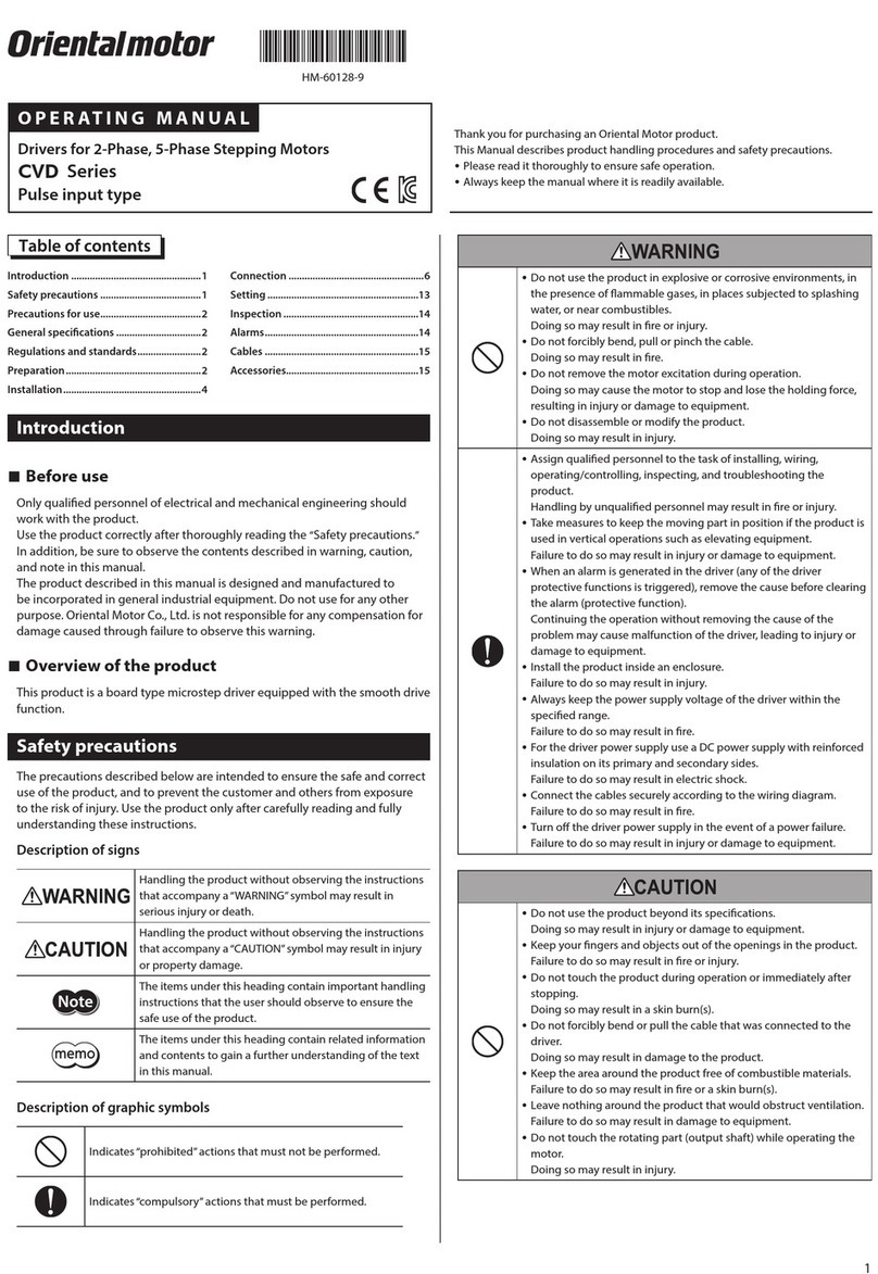
Oriental motor CVD Series User manual

Oriental motor

Oriental motor CVD Series User manual

Oriental motor KII Series User manual

Oriental motor

Oriental motor KII Series User manual

Oriental motor SMK Series User manual

Oriental motor

Oriental motor SMK Series User manual

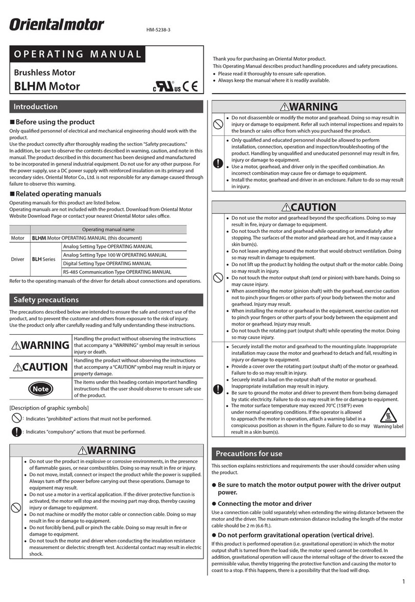
Oriental motor BLM Series User manual

Oriental motor

Oriental motor BLM Series User manual

Oriental motor UFK-W Series User manual

Oriental motor

Oriental motor UFK-W Series User manual

Oriental motor BLV Series User manual

Oriental motor

Oriental motor BLV Series User manual

Oriental motor World K Series User manual

Oriental motor

Oriental motor World K Series User manual

Oriental motor FPW Series User manual

Oriental motor

Oriental motor FPW Series User manual

Oriental motor BXII Series User manual

Oriental motor

Oriental motor BXII Series User manual

Oriental motor NX Series User manual

Oriental motor

Oriental motor NX Series User manual

Oriental motor World K Series User manual

Oriental motor

Oriental motor World K Series User manual

Oriental motor CVD512B*-KSC series User manual

Oriental motor

Oriental motor CVD512B*-KSC series User manual

Oriental motor PKP Series User manual

Oriental motor

Oriental motor PKP Series User manual

Oriental motor FPW Series User manual

Oriental motor

Oriental motor FPW Series User manual

Oriental motor NX Series User manual

Oriental motor

Oriental motor NX Series User manual

Oriental motor SPR II Series User manual

Oriental motor

Oriental motor SPR II Series User manual

Oriental motor CRK Series User manual

Oriental motor

Oriental motor CRK Series User manual

Oriental motor PK Series User manual

Oriental motor

Oriental motor PK Series User manual

Oriental motor RKII Series User manual

Oriental motor

Oriental motor RKII Series User manual

Oriental motor BMU Series User manual

Oriental motor

Oriental motor BMU Series User manual

Oriental motor World K Series User manual

Oriental motor

Oriental motor World K Series User manual

Oriental motor AZM14 User manual

Oriental motor

Oriental motor AZM14 User manual

Oriental motor BLE2 Series User manual

Oriental motor

Oriental motor BLE2 Series User manual

Oriental motor BLE23AR*S Series User manual

Oriental motor

Oriental motor BLE23AR*S Series User manual

Popular Engine manuals by other brands

SOMFY Orea 60 WT Installer's guide

SOMFY

SOMFY Orea 60 WT Installer's guide

Lombardini LMG 4000 owner's manual

Lombardini

Lombardini LMG 4000 owner's manual

Rockwell Automation Allen-Bradley Kinetix MMA-B080 Series installation instructions

Rockwell Automation

Rockwell Automation Allen-Bradley Kinetix MMA-B080 Series installation instructions

Dynabrade 95524 Assembly instructions

Dynabrade

Dynabrade 95524 Assembly instructions

Panasonic Minas E Series instruction manual

Panasonic

Panasonic Minas E Series instruction manual

SOMFY Tilt & Lift 25 RTS Central instructions

SOMFY

SOMFY Tilt & Lift 25 RTS Central instructions

Nice SD Instructions and information for installation and use

Nice

Nice SD Instructions and information for installation and use

Briggs & Stratton 194700 Series Operator owner's manual

Briggs & Stratton

Briggs & Stratton 194700 Series Operator owner's manual

DANA BREVINI T Series Installation and maintenance manual

DANA

DANA BREVINI T Series Installation and maintenance manual

Kohler KD62V12 Operation and maintenance manual

Kohler

Kohler KD62V12 Operation and maintenance manual

LOMBARDINI MARINE LDW 194 JMTI Installation - use - maintenance

LOMBARDINI MARINE

LOMBARDINI MARINE LDW 194 JMTI Installation - use - maintenance

Briggs & Stratton VANGUARD 25V000 Operator's manual

Briggs & Stratton

Briggs & Stratton VANGUARD 25V000 Operator's manual

Kohler Command PRO CH640 owner's manual

Kohler

Kohler Command PRO CH640 owner's manual

Perkins New 1000 Series Workshop manual

Perkins

Perkins New 1000 Series Workshop manual

JayKay E-FIN user manual

JayKay

JayKay E-FIN user manual

Navistar INTERNATIONAL DT 466 DIAGNOSTIC/TROUBLESHOOTING MANUAL

Navistar

Navistar INTERNATIONAL DT 466 DIAGNOSTIC/TROUBLESHOOTING MANUAL

Desert Aircraft DA 100 EFI owner's manual

Desert Aircraft

Desert Aircraft DA 100 EFI owner's manual

Bosch Rexroth MKE035B-144 Project planning manual

Bosch

Bosch Rexroth MKE035B-144 Project planning manual

manuals.online logo
manuals.online logoBrands
  • About & Mission
  • Contact us
  • Privacy Policy
  • Terms and Conditions

Copyright 2025 Manuals.Online. All Rights Reserved.