Maintenance
Safety
Maintenance D42doc061507 2-1
2
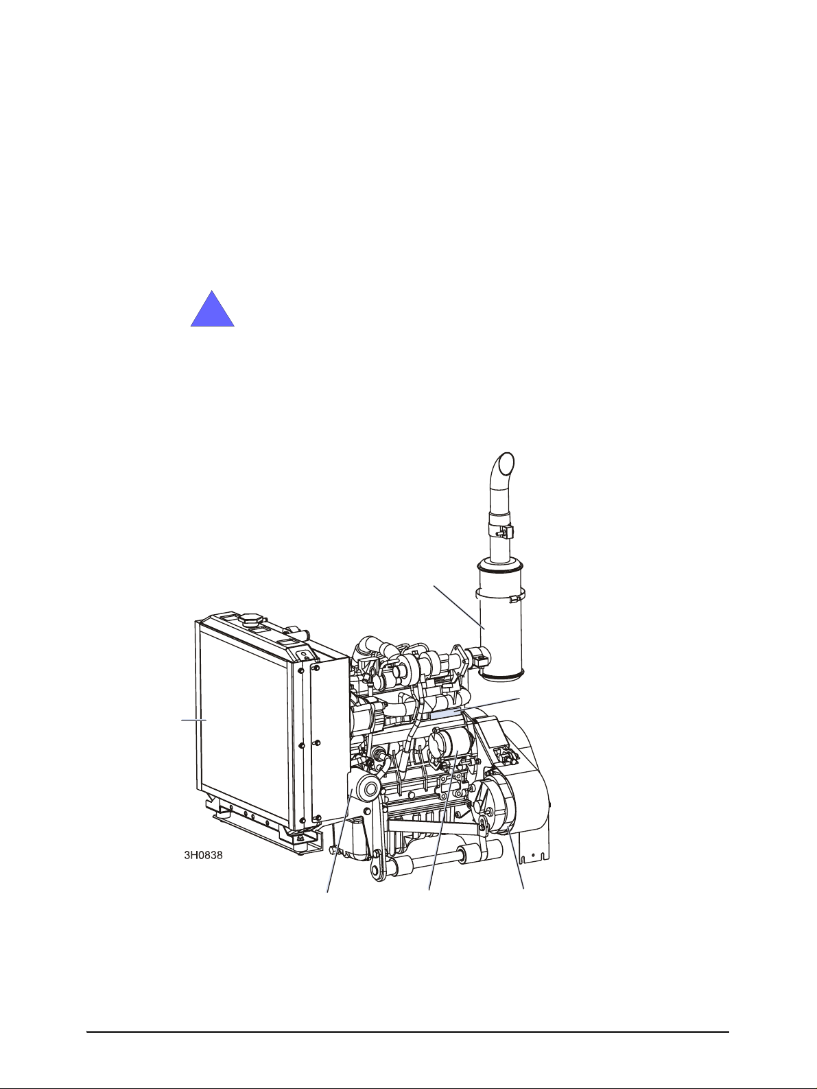
SECTION 2 MAINTENANCE
Refer to the manufacturer’s manual for maintenance intervals and procedures unless oth-
erwise instructed in this manual. Follow the manufacturer’s recommendations for dusty
conditions.
IMPORTANT! This manual only provides information about
additional procedures or procedures to be performed at dif-
ferent time intervals than found in the manufacturer's manu-
als. Refer to the manufacturer's manual for complete
maintenance instructions.
2.1 Safety
Use caution when performing maintenance or service to the engine.
DANGER! Always be aware of and take proper protective
measures against rotating shafts, pulleys, fans, etc. Always
stay a safe distance from rotating members and make sure
that loose clothing or long hair does not engage rotating
members resulting in possible injury.
DANGER! Engine components can become very hot during
operation. Avoid contact with any part of a hot engine. The
exhaust components of your engine are especially hot dur-
ing and following operation. Contact with hot engine com-
ponents can cause serious burns. Therefore, never touch
or perform service functions on a hot engine. Allow the
engine to cool sufficiently before beginning any service
function.
WARNING! Remove the blade before performing any
engine service. Failure to do so may result in serious injury.
WARNING! Always wear proper and necessary safety
equipment when performing service functions. Proper
safety equipment includes eye protection, breathing protec-
tion, hand protection and foot protection.
This symbol identifies the interval (hours of operation) at which each maintenance pro-
cedure should be performed. "AR" signifies maintenance procedures which should be
performed as required.
!
0