Tomei EXPREME Ti TB6090-NS02A User manual

2016年03月 ATUM102Y0101
チタニウムマフラー
TITANIUM MUFFLER
日本語 **************2p
English **************6p
●この取扱説明書を良く読んでからお使いください。
●日産自動車の発行する整備要領書と併せてお使いください。
●取り付け後も大切に保管してください。
●販売店様で取り付けをされる場合は本書を必ずお客様へお渡しください。
TOMEI 製品のお買い上げありがとうございます。
TOMEIチタニウムマフラーはサーキットなどの走行時、軽量化や排気効率を重視した
仕様に効果的です。
● Please read this manual carefully prior to installation.
適合
APPLICATION
品番
PART NUMBER
NISSAN FAIRLADY Z Z34/370Z TB6090-NS02A
NISSAN FAIRLADY Z Z33/350Z 440014
INSTALLATION MANUA
L
1
yp
● Please also refer to the NISSAN Service Manual
● After installation, keep this manual safe for future reference.
● If the installation is to be completed in a shop/garage please ensure this manual
is given to the customer or end user.
Thank you for purchasing a TOMEI product.
This TOMEI Powered product is designed to enhance exhaust flow efficiency and maximize
the engines true performance potential. Being lightweight, it also helps improve
the cars overall performance during competition use.
1

部品構成 下記の内容・数量が揃っているかを確認してください。
※図はZ34/370Z
作業に必要な工具類 取り付けには下記が必要です。
エンジン整備用工具 式
トルクレンチ
整備要領書
フランジナット
M10 (2) / M8 (1)
スプリング (4)
メインパイプA (1)
ボルトスムース
ペースト(1)
EXPREME Ti ステッカー (2)
メインパイプB (1)
サイレンサーASSY (1)
クランプバンド (2)
サイレンサーバンドラバー (1)
サウンドレデューサー (1) ボタンボルト (1)
6角レンチ (1)
サイレンサーバンド (1)
フランジボルト
M8 L=25 (1)
ガスケット (1)
2
注意
■本品は自動車競技専用部品です。サーキットや公道から閉鎖された場所内に限って使用してください。
■本品の取り付けは特別の訓練を受けた整備士が、設備の整った作業場で実施してください。
■指定する車種以外への取り付けはおやめください。本品およびエンジンを破損する恐れがあります。
■取り付けの際は、適切な工具、保護具を使用しないと、けがにつながり危険です。
警 告
■本品の取り付けはエンジン及びエンジンルーム内が冷えた状態で行ってください。
■部品欠落による車輌の破損・火災が起こる可能性があるため、また、後続・周辺車両へ被害が及ぶ
おそれがあるため、製品構成部品の取り付けは確実に行ってください。
・エンジン整備用工具一式 ・トルクレンチ ・整備要領書
2

1.純正エキゾーストマフラーの取り外し
ここで記載するのは簡易手順です。各部の詳細な脱着方法は、必ず整備要領書を参照してください。
1 バッテリーマイナス端子を取り外す。
2 センターマフラー、メインマフラーを取り外す。
3 メインマフラー右側、左前側のマウントラバーをそれぞれ取り外す。
2.TOMEI チタニウムマフラーの取付け
【各部品の装着位置図】
同梱の部品の使用箇所は下図の通りです。
① メインパイプA ⑧ サイレンサーバンド
② メインパイプB ⑨ サイレンサーバンドラバー
③ サイレンサーASSY ⑩ フランジボルト M8
④ ガスケット ⑪ フランジナット M8【20.0~28.0N・m (2.0~2.9kgf-m)】
⑤ フランジナット M10 【34.0~39.0N・m (3.5~4.0kgf-m)】 ⑫ サウンドレデューサー
⑥ クランプバンド【25.0N・m (2.6kgf-m)】 ⑬ ボタンボルト M6【8.0~12.0N・m(0.8~1.2kgf-m)】
①
②
③
④⑤※
⑬
⑨
⑥
⑩
⑫
<キット内付属品使用箇所と締付けトルク>
⑪
⑦
⑧
⑤※ ⑥
⑦
⑦
⑦
3
⑦スプリング
※高熱にさらされる部分には焼き付きや固着を防止するため、付属のボルトスムースペーストを塗布して下さい。
※図はZ34/370Z
【装着手順】
1. メインパイプAを付属のフランジナットM10を使用し仮組みする。
この時、差込部のパイプストッパーが上側を向くように取り付ける。
※付属ガスケット(上図④)、フランジナットM10(上図⑤)使用。
2. メインパイプBにクランプバンドを通し、各パイプのスプリングフック位置どうしが平行になるように、
メインパイプAに差し込む。同時にマフラーハンガーを取り付ける。
※付属クランプバンド(上図⑥)使用。
3. サイレンサーASSYにクランプバンドを通し、スプリングフック位置どうしが平行になるように、
メインパイプBに差し込む。
※付属クランプバンド(上図⑥)使用。
サイレンサーASSYのプレスマークが真下にくるようにして下さい。
3

4. サイレンサーバンドにサイレンサーラバーを取り付け、サイレンサーに傷を付けないように
注意しながら、エキゾーストハンガーに取り付ける。
※付属サイレンサーバンド(前頁⑧)、サイレンサーバンドラバー(前頁⑨)
フランジボルトM8(前頁⑩)、フランジナット(前頁⑪)使用。
5. 各部のクリアランスに注意しながら、前側から順に本締めを行う。
締付トルク フランジナットM10部分 (前頁⑤)【34~39N・m(3.5~4.0kgf-m)】
フランジナットM8部分 (前頁⑪)【20~28N・m(2.0~2.9kgf-m)】
クランプバンド部分 (前頁⑥)【25N・m(2.6kgf-m)】
6. メインパイプA、メインパイプB・サイレンサーASSYの各部にスプリングを取り付ける。
※付属スプリング(前頁⑦)使用。
注意
・車体各部とのクリアランスや、干渉のないことを確認して本締めを行ってください。
なお、車両個体差により十分なクリアランスが得られない場合は、触媒・エキゾーストフロントチューブの
取り付けボルトを各部が動く程度に緩め、本品の装着クリアランスを調整した後、本締めして下さい。
・マフラーに油分などが付着した状態で使用すると、汚れや焼けの原因となります。
取付け後は必ず脱脂を行ってください。
・装着・使用状況により、リア・バンパーが溶ける可能性があります。
必要に応じ、遮熱対策を行ってください。
7. 必要に応じ、サウンドレデューサーの取り付けを行なう。
※付属サウンドレデューサー (3ページ図中⑫)
ボタンボルトM6 (3ページ図中⑬)使用
締付トルク [8~12N・m(0.8~1.2kgf-m)]
警 告
・サウンドレデューサーを取り付けたまま、高速走行を
行なわないでください。部品破損の可能性があります。
・サウンドレデューサーの脱着はマフラーが冷えた状態で
行なってください。
4
8. バッテリーマイナス端子を取り付ける。
4

3. 取り付け後の確認
1.各部に干渉がないか再度確認する。
2.エンジンを始動し、アイドリングから約2500rpm程度まで回転を上げ、排気漏れや異常音がないか確認する。
3.試運転を行い、再度排気漏れや異常音がないか確認する。
警 告
・干渉があると周辺部品が損傷し、車両火災や故障の原因となるため、確認は慎重に行ってください。
・排気漏れがあると、性能の低下や排気ガスによる中毒を起こす原因となり、危険です。
・走行中に異常を感じた場合は直ちに走行を中止し、確認を行ってください。
・その場で修復を行う場合は、マフラーが十分に冷えた状態で行ってください。
・部品の脱落等が生じている場合は、エンジンを再始動せず、専門業者に修理を依頼し、
指示に従ってください。
注意
・本品を装着した際、車両仕様によってはエンジン特性に変化がある場合があります。
装着後は、エンジンセッティングを確認し、必要に応じてそれらの再セッティングを行ってください。
55
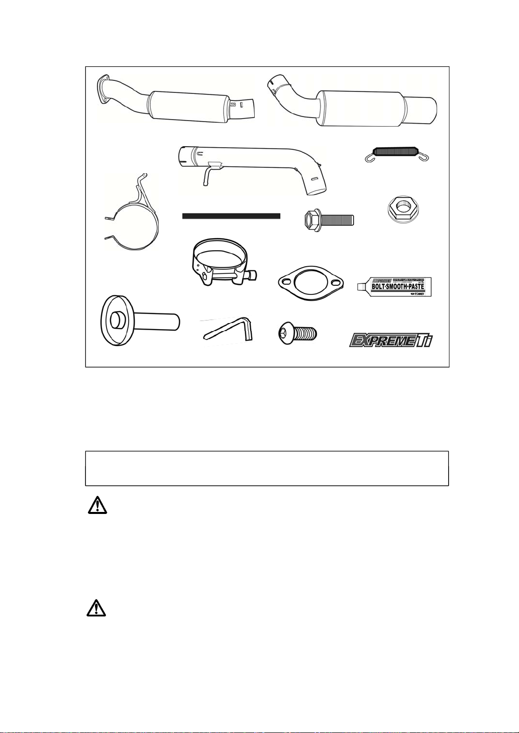
KIT CONTENTS Below are the kit contents. The quantity of each items are noted in brackets ().
※Z34/370Z version pictured above.
REQUIRED TOOLS The following tools are required for installation.
FLANGE NUT
M10 (2) / M8 (1)
SPRING (4)
MAIN PIPE A (1)
BOLT SMOOTH
PASTE (1)
EXPREME Ti STICKER (2)
MAIN PIPE B (1)
SILENCER ASSY (1)
CLAMP BAND (2)
SILENCER BAND RUBBER (1)
SOUND REDUCER (1) BUTTON BOLT (1)
ALLEN KEY (1)
SILENCER BAND (1)
FLANGE BOLT
M8 L=25 (1)
GASKET (1)
* General Engine MaintenanceTools * Torque Wrench * Service Manual
6
CAUTION
■ This product is designed to be used for off road competition purposes only.
■ This product should be installed by a trained professional in a well-equipped workshop.
■Only install this product on the specified vehicles to avoid product and/or engine damage.
■ Do not use excessive force when attaching or removing components as this may damage the item.
■ When installing, use the appropriate tools and safety gear to avoid injury.
WARNING
■ This product is to be installed only when both the engine and engine bay are cold.
■ Ensure that all parts are fitted correctly during installation to avoid potential fire hazards
and/or damage.
*
G
enera
l
E
ng
i
ne
M
a
i
n
t
enance
T
oo
l
s
*
T
orque
W
renc
h
*
S
erv
i
ce
M
anua
l
6

1. REMOVAL OF THE STOCK STANDARD EXHAUST MUFFLER
This manual only provides basic instructions. For more details please refer to the vehicles
official factory service manual.
1. Disconnect the car's negative battery terminal.
2 Remove both the center muffler section and the main muffler.
3 Disconnect the rubber mounts from the right and front-left side of the main muffler.
2.INSTALLATION OF THE TOMEI TITANIUM MUFFLER
【Illustration of the mounting position of each bolt & gasket】
The installation of the supplied parts are as shown below.
① MAIN PIPE A ⑧ SILENCER BAND
② MAIN PIPE B ⑨ SILENCER BAND RUBBER
③ SILENCER ASSY ⑩ FLANGE BOLT M8
④ GASKET ⑪ FLANGE NUT M8 【20.0~28.0N・m (2.0~2.9kgf-m)】
⑤ FLANGE NUT M10 【34.0~39.0N・m (3.5~4.0kgf-m)】 ⑫ SOUND REDUCER
⑥ CLAMP BAND 【25.0N・m (2.6kgf-m)】 ⑬ BUTTON BOLT M6 【8.0~12.0N・m(0.8~1.2kgf-m)】
⑦ SPRING
※Apply the Bolt Smooth Paste (included) to the parts which will be exposed to high temperatures.
①
②
③
④⑤※
⑬
⑨
⑥
⑩⑫
⑪
⑦
⑧
⑤※ ⑥
⑦
⑦
⑦
<Components&torquespecs>
7
※Apply
the
Bolt
Smooth
Paste
(included)
to
the
parts
which
will
be
exposed
to
high
temperatures.
This helps prevent the parts from sticking and/or becoming seized.
※Z34/370Z version pictured above.
【Installation Procedure】
1. Test fit the Main Pipe A with the included M10 Flange nuts.
Ensure that the stopper on the Main Pipe A is facing up.
※Use the supplied gasket (④,shown above ) with the M10 Flange Nut (⑤,shown above).
2. Fit one of the Clamp Bands to the Main Pipe B. Next, attach the Main Pipe B to the Main Pipe A
whilst ensuring all spring hooks align parallel to one another.
The Muffler Hanger should also be attached at this stage.
※Use the included Clamp Band (⑥, shown above).
3. Fit the second Clamp Band to the Silencer assembly and attach to the Main Pipe B.
Ensure all spring hooks align parallel to one another.
※Use the included Clamp Band (⑥, shown above).
Position the Silencer Assembly with the embossed logo facing down.
7

4. Fit the Silencer Rubber to the Silencer Band. Now carefully mount the silencer to the exhaust hanger
so as not to scratch it.
※Use the Silencer Band (⑧, previous page) , Silencer Band Rubber (⑨, previous page)
with the M8 Flange Bolts (⑩, previous page) , and Flange Nuts (⑪, previous page).
5. Ensuring sufficient clearance is maintained, tighten down the bolts in order starting from the front.
Torque Specs Flange Nut M10 (Previous Page ⑤) 【34~39N・m(3.5~4.0kgf-m)】
Flange Nut M8 (Previous Page ⑪)【20~28N・m(2.0~2.9kgf-m)】
Clamp Band (Previous Page ⑥)【25N・m(2.6kgf-m)】
6. Connect the Main Pipe A/B, Main Pipe B and Silencer Assembly with the Spring Mounts.
※Use the Springs included in the kit (⑦, Previous Page).
CAUTION
・Ensure sufficient clearance and correct fitment has been achieved before tightening down the nuts
and bolts completely.
In some cases, there may be insufficient clearance due to differences in vehicle specification. In such a case,
loosen the bolts of each component and adjust the positioning until sufficient clearance is achieved
before re-tightening down all the bolts.
・Using the product whilst there is oil or other debris on it can cause blemishes and/or burn marks.
· After fitting the exhaust, check to see if the rear bumper will
be at risk from heat damage. You may need apply additional heat
protection to the rear bumper.
7. The sound reducer can also be installed if required.
※ Sound Reducer accessories (⑫)
Button Bolt M6 (⑬)
Tightening torque [8~12 N・m (0.8~1.2kgf-m)]
WARNING
* Using the sound reducer at high speed or high RPM could
cause damage to the component(s)
8
* Only install or remove the sound reducer when the engine and exhaust are cool
to avoid injury.
8. Reconnect the car's negative battery terminal.
8

3. INSTALLATION VERIFICATION
1. Check to ensure the product is fitted correctly.
2. Start the engine and rev to 2500rpm to check for any abnormal sounds.
3. Test drive the vehicle and check for abnormal sounds and/or loose parts.
WARNING
・ Be thorough when performing checks as incorrect fitment or loose parts can result in reduced performance
and/or damage to other surrounding parts and components.
・ Exhaust leaks not only reduce performance but can also be a health hazard and should be addressed
immediately.
・ When using the vehicle, If there are any abnormalities, stop the vehicle immediately and check for faults.
・ Ensure the engine and/or engine bay is cool before attempting any repairs.
・ Should any part fall off, do not restart the engine. Consult a trained professional and follow their instructions.
CAUTION
・ Once the product has been installed on the vehicle, the engine characteristics may change depending
on the setup. After installation, adjust the engine/ECU settings as necessary.
99

1010

1111

12
13 Orchard Suite 107
Lake Forest, CA 92630, USA
TEL : +1-949-855-6577
FAX : +1-949-855-6525
OPEN: Monday - Friday (National holidays and public holidays excluded).
10:00 - 19:00 PST
Web: www.tomeiusa.com
Email: tomei@tomeiusa.com
TOMEIPOWEREDUSAINC.
12
This manual suits for next models
1
Table of contents
Other Tomei Automobile Accessories manuals


Popular Automobile Accessories manuals by other brands

On the Rox
On the Rox Folding Windshield installation guide

Dometic
Dometic DVF Holding Tank Vent Filter Installation and operating manual

Witter Towbar Systems
Witter Towbar Systems ZX504 quick guide

Pro-gard Products LLC.
Pro-gard Products LLC. G5510 installation guide

Carefree
Carefree MARQUEE Service manual

HP
HP iPAQ user manual


