Tomei Expreme Ti Guide

2018_8 M-TB6090-TY04A
目次 / INDEX
このたびは弊社製品をお買い上げいただき、まことにありがとうございます。
ご使用前にこの説明書をよくお読みのうえ正しくお使いください。
お読みになった後もすぐ取り出せる場所に大切に保管してください。
説明書に書かれている注意事項は必ず守ってください。
各自動車メーカーの発行する整備要領書が必要になります。本書と合わせてお使いください。
不適切な使用により事故が生じた場合、弊社では責任を負いかねますので、
あらかじめご了承ください。
販売店様で取り付けをされる場合は本書を必ずお客様へお渡しください。
Thank you for purchasing a TOMEI product.
Please read this installation manual carefully prior to installation/use.
Ensure you keep this document stored in a safe location for future reference.
Pay close attention to and adhere to the various warnings/cautions contained herein.
You should also consult the official servicing manual for your vehicle when installing this product.
Please note that inappropriate installation/use of this product will be at the owner's own
risk and/or responsibility.
Retailers/Workshops should ensure this document is given to the end user.
TOYOTA JZX100 1JZ-GTE
TB6090-TY04A
適合
APPLICATION
品番
PART NUMBER
FULL TITANIUM MUFFLER KIT
P2
P10 English
INSTALLATION MANUAL
1

部品構成 下記の部品・数量が揃っているかご確認ください。
名称 メインパイプA 名称 メインパイプB
同梱数量 1同梱数量 1
単品品番 TB6090-TY04-01 単品品番 TB6090-TY04-02
名称 サイレンサー 名称 ガスケット
同梱数量 1同梱数量 1
単品品番 TB6090-TY04-03 単品品番 PB6150-FGK32
名称 フランジボルト M10 名称 フランジナット M10
同梱数量 2同梱数量 2
単品品番 PB6150-FBT02 単品品番 PB6150-FNT02
名称 クランプバンド 名称 スプリング
同梱数量 2同梱数量 2
単品品番 PB6150-MCB01 単品品番 PB609B-SPR01
名称 サイレンサーバンド 名称 サイレンサーバンドラバーΦ152
同梱数量 1同梱数量 1
単品品番 TB6090-TY04-04 単品品番 PB609B-SBR01
①
②
③
④
⑦
⑧
⑨
⑩
⑤
⑥
2

名称 フランジボルト M8 名称 フランジナット M8
同梱数量 1同梱数量 1
単品品番 PB6150-FBT01 単品品番 PB6150-FNT01
名称 サウンドレデューサー ver.2 Φ115 名称 ボルトスムースペースト
同梱数量 1同梱数量 1
キット品番 PB609B-INS04
構成部品
品番 名称 数量
PB609B-INS05-01
MAIN REDUCER 1
PB609B-INS04-02
SUB REDUCER 1
PB6150-BBT01 BUTTON BOLT M6*P1.0 3
PB6150-FNT12
FLANGE NUT M6*P1.0 3
PB6150-FBT13
FLANGE BOLT M6*P1.0 1
名称 タイラップ
同梱数量 1
単品品番
PB6150-ZIP01
PART HEX KEY 名称 EXPREME Tiステッカー
QTY. 1 同梱数量 2
PART No. PB609B-HDT01 単品品番 TG202A-0000A
名称 TOMEIステッカー 名称 TOMEIエンブレム
同梱数量 2同梱数量 1
単品品番 TG201A-0000A 単品品番 TE501A-0000A
⑪
⑫
⑰
⑱
⑬
⑯
単品品番
PB6150-BSP01
⑭
⑮
⑲
3

取付作業に必要な工具類
■エンジン整備工具一式 ■トルクレンチ ■整備要領書 ■ハンドドリル
■センタードリル・Φ6.5mmドリル ■保護具
注 意
■ この取扱説明書は製品に関わる特記事項についてまとめたものです。
実際の作業や手順については各自動車メーカー発行の整備要領書をご確認ください。
■
本製品は自動車競技部品です。サーキットなどの公道ではない閉鎖された場所で使用してください。
■ 本製品の取り付けは設備の整った環境で、資格をもった整備士が行ってください。
■ 適合する車種以外へのご使用はおやめください。本製品および、エンジンを破損する恐れがあります。
■ 本製品の取り付けに必要な各部品の脱着の際には指定トルクなどを守り、無理な力を加えないで
ください。本製品および、エンジンを破損する恐れがあります。
■ 本製品を取り付ける際には、適切な工具、保護具を使用してください。
ご使用にならないとけがにつながり危険です。
警 告
■ 本製品の取り付けはエンジンおよび、エキゾーストシステムが十分に冷えた状態で行ってください。
■
部品の欠落により車両の破損・火災が起こる可能性や、後続・周辺車両へ害がおよぶ
恐れがあるため、製品構成部品の取り付けは確実に行ってください。
1.
純正エキゾーストマフラーの取り外し
ここで記載するのは簡易手順です。各部の詳細な脱着方法は、必ず整備要領書を参照してください。
1. バッテリーマイナス端子を取り外す。
2. テールパイプASSY(リアサイレンサー)を取り外す。
3. センターパイプASSYを取り外す。
4

2. サウンドレデューサー取り付け穴の加工
本製品は付属のサウンドレデューサーを使用することにより、音量を3段階に調整することが出来ます。
STANDARD QUIET MODE 1 QUIET MODE 2
そのままでご使用いただけます。 そのままでご使用いただけます。 必ず追加工が必要です。
警 告
■ テールエンドにはあらかじめ取り付け穴が1ヶ所あいていますが、MODE 2の状態でご使用される場合、
必ず下記加工要領を参考に追加工を施して、確実にサウンドレデューサーを固定してください。
なお、MODE 1の状態ではそのままご使用できますが、追加工を行う事でより安全にご使用いただけます。
警 告
■この加工を行なわない場合、部品の欠落により後続・周辺車両へ被害が及ぶ恐れがあります。
■また、サイレンサーテールエンドの変形・破損が起こる場合があります。
注意
■上図の基準穴を基に加工を行なう。
1. サイレンサー内部に切り粉が入らないようにウエス等で保護する。
2.
テールエンド端面より基準穴があいている距離を確認する。(基準値15mm)
3. サウンドレデューサーを軽く差し込み穴位置センターをマーキングする。(2ヶ所)
4.
基準穴を合わせ、ボタンボルトM6・フランジナットM6でサウンドレデューサーを固定する。
この時、まっすぐに差し込まれているか、サウンドレデューサー穴位置が基準値
(15mm程度)にあるか、同時に確認する。(次頁マーキング位置図参照)
※ボタンボルトM6、フランジナットM6使用。
5

サウンドレデューサーの位置確認図(取り付け穴センターがテールエンド端面から15mm)
5.
センタードリルにてマーキングのセンターに下穴をあける。
6.
ずれていないようであればΦ6.5mm程度(M6ボルトが入るサイズ)にて穴あけ加工を行う。
7.
加工したボルト穴にボタンボルトM6・フランジナットM6を取り付け、固定する。
8.
再度、サウンドレデューサー穴位置を確認し、3ヶ所目も同様に穴あけ加工を行なう。
9.
全ての穴あけ加工終了後、テールエンドおよびサウンドレデューサーのバリ取りを行う。
10.
切り粉を除去する。
15mm /
6

3. TOMEIチタニウムマフラーの取り付け
【各部品の装着位置図】
同梱部品の装着箇所は下図の通りです。
<キット同梱部品使用箇所と締付トルク>
① メインパイプA ⑨ サイレンサーバンド
② メインパイプB ⑩ サイレンサーバンドラバー
③ サイレンサー ⑪ フランジボルト M8 L=25mm
④ ガスケット ⑫ フランジナット M8 [19.6~28.4N.m(2.0~2.9kgf-m)]
⑤ フランジボルトM10 ⑬ サウンドレデューサー
⑥ フランジナットM10 [34.3~39.2N.m(3.5~4.0kgf-m)] ⑭ ボタンボルト M6
⑦ クランプバンド [25.0N.m(2.55kgf-m)] ⑮ フランジナット M6 [7.8~11.8N.m(0.8~1.2kgf-m)]
⑧ スプリング ⑯ タイラップ
※ 高温にさらされる部分には焼付きや固着を防止するため、付属のボルトスムースペーストを塗布してください。
7

【装着手順】
1. メインパイプAを付属のガスケット・フランジボルトM10、フランジナットM10を使用し、仮組みする。
※ ・メインパイプA(前頁①) ・付属ガスケット(前頁④)
・フランジボルトM10(前頁⑤) ・フランジナットM10(前頁⑥)使用。
2. メインパイプBにクランプバンドを通し、スプリングフック位置が平行になるようにメインパイプAに差し込む。
※ メインパイプB(前頁②) ・付属クランプバンド(前頁⑦)使用。
3. サイレンサーにクランプバンドを通し、スプリングフック位置が平行になるようにメインパイプBに差し込む。
※
・サイレンサー(前頁③) ・付属クランプバンド(前頁⑦)使用。
サイレンサーASSYのプレスマークが真下にくるように装着してください。
4.
サイレンサーバンドにサイレンサーバンドラバーを取り付け、サイレンサーに傷をつけないように注意しながら、
エキゾーストハンガーに取り付ける。
※ ・付属サイレンサーバンド(前頁⑨) ・サイレンサーバンドラバー(前頁⑩)使用。
5. 各部のクリアランスに注意しながら前側から順に本締めを行う。
締付トルク フランジナットM10部分 (前頁⑥)[34.3~39.2N.m(3.5~4.0kgf-m)]
フランジナットM8部分 (前頁⑫)[19.6~28.4N.m(2.0~2.9kgf-m)]
クランプバンド部分
(前頁⑦)[25.0N.m(2.55kgf-m)]
6. メインパイプA及びB、サイレンサーの各部にスプリングを取り付ける。
注 意
■ 車体各部とのクリアランスや、干渉のない事を確認してから本締めを行ってください。
なお、車両個体差により十分なクリアランスが得られない場合は、触媒の取り付けボルトを
各部が動く程度に緩め、本品の装着クリアランスを確保した後、本締めしてください。
■ マフラーに油分などが付着した状態で使用すると、汚れや焼けの原因となります。
取付後は、必ず脱脂を行ってください。
■ 装着・使用状況により、周辺部品に熱害が及ぶ可能性があります。
必要に応じ、遮熱対策を行ってください。
7. 右図を参考にして、マフラーの振れが過大にならないよう
サイレンサーのハンガー部をタイラップで固定する。
※ 付属タイラップ(前頁⑯)使用。
8. 必要に応じ、サウンドレデューサーの取付を行う。
※ 付属サウンドレデューサー(前頁⑬)・
ボタンボルトM6(前頁⑭)フランジナット M6(前頁⑮)使用。
ボタンボルトM6 【7.8~11.8N.m(0.8~1.2kgf-m)】
警 告
■ サウンドレデューサーを取り付けたまま、高速走行を行わないでください。
部品破損の可能性があります。
■ サウンドレデューサーの脱着は、マフラーが冷えた状態で行ってください。
9. バッテリーマイナス端子を取り付ける。
<締付トルク>
8

4. 取り付け後の確認
1. 各部に干渉がないか、再度確認する。
2. エンジンを始動し、アイドリングから約2500rpm程度まで回転を上げ、異常音がないか確認する。
3. 試運転を行い、再度緩みや異常音がないか確認する。
警 告
■ 緩みや干渉があると性能の低下や、周辺部品が損傷し故障の原因となるため、確認は慎重に
行ってください。
■ 排気漏れがあると、性能の低下や排気ガスによる中毒を起こす原因となり危険です。
■
走行中に異常を感じた場合は直ちに走行を中止し、確認を行ってください。
■ その場で修復を行う場合は、エキゾーストシステムが十分に冷えた状態で行ってください。
■ 部品の脱落等が生じている場合は、エンジンを再始動せず、専門業者に修理を依頼し、
指示に従ってください。
注 意
■ 本品を装着した際、車両仕様によってはエンジン特性に大きな変化がある場合があります。
装着後は、エンジンセッティングを確認し、必要に応じてそれらの再セッティングを行って
ください。
9

KIT CONTENTS
Check to ensure all the following items are included in this kit.
PART MAIN PIPE A PART MAIN PIPE B
QTY. 1 QTY. 1
PART No. TB6090-TY04-01 PART No. TB6090-TY04-02
PART SILENCER PART
GASKET
QTY. 1 QTY. 1
PART No. TB6090-TY04-03 PART No. PB6150-FGK32
PART
FLANGE BOLT M10
PART FLANGE NUT M10
QTY. 2 QTY. 2
PART No. PB6150-FBT02 PART No. PB6150-FNT02
PART CLAMP BAND PART SPRING
QTY. 2 QTY. 2
PART No. PB6150-MCB01 PART No. PB609B-SPR01
PART
SILENCER BAND
PART SILENCER BAND RUBBERΦ152
QTY. 1 QTY. 1
PART No. TB6090-TY04-04 PART No. PB609B-SBR01
①
②
④
⑤
⑥
⑦
⑧
⑨
⑩
③
10

PART FLANGE BOLT M8 PART FLANGE NUT M8
QTY. 1 QTY. 1
PART No. PB6150-FBT01 PART No. PB6150-FNT01
PART SOUND REDUCER ver.2 Φ115 PART BOLT SMOOTH PASTE
QTY. 1 QTY. 1
KIT PART No.
PB609B-INS04
CONTENTS
PART No. PART QTY
PB609B-INS05-01
MAIN REDUCER 1
PB609B-INS04-02
SUB REDUCER 1
PB6150-BBT01 BUTTON BOLT M6*P1.0 3
PB6150-FNT12
FLANGE NUT M6*P1.0 3
PB6150-FBT13
FLANGE BOLT M6*P1.0 1
PART ZIP TIE
QTY. 1
PART No.
PB6150-ZIP01
PART HEX KEY PART EXPREME Ti STICKER
QTY. 1 QTY. 2
PART No. PB609B-HDT01 PART No. TG202A-0000A
PART TOMEI STICKER PART TOMEI EMBLEM
QTY. 2 QTY. 1
PART No. TG201A-0000A PART No. TE501A-0000A
⑯
PB6150-BSP01
⑮
⑭
PART No.
⑰
⑱
⑲
⑪
⑫
⑬
11

REQUIRED TOOLS FOR INSTALLATION
■General engine maintenance tools ■
Torque wrench
■
Official servicing manual
■Hand Drill
■ Center Drill and Φ6.5mm Drill Bit ■ Safety Gear
CAUTION
■The information continued in this installation manual is specific to this product.
For details regarding the removal/installation of stock components, please refer to the
vehicle's official servicing manual.
■
This product is intended for motorsport/competition use and should
NOT
be used on public roads.
■
This product should be installed by a trained professional in a well-equipped workshop.
■Only install this product on the specified vehicle(s) to avoid product and/or engine damage.
■
Ensure the appropriate amount of torque is used to remove/install the fastenings. Do
NOT
use
excessive force as this can damage the product and/or the engine.
■Always use the appropriate tools and safety equipment when installing this product.
Failing to do so is extremely dangerous and may result in injury.
WARNING
■Only install this product when the engine and all related components are cold.
■Ensure that all parts are fitted correctly during installation to avoid potential fir hazards
and/or damage. Failing to do so is not only dangerous to you but also those around you.
1. REMOVING THE STOCK EXHAUST
This manual only provides basic instructions. For more details, please refer to the vehicle's
official servicing manual.
1. Disconnect the negative battery terminal.
2. Remove the tail pipe assy.
3. Remove the center pipe assy.
12

2. ADDING EXTRA BOLT HOLES
FOR THE SOUND REDUCER
■The loudness of the exhaust can be set at 3 different levels using the included sound reducer.
STANDARD QUIET MODE 1 QUIET MODE 2
Without sound reducer. Can be used with just one bolt. Ensure you add the extra bolts
and bolt holes.
WARNING
■
The exhaust tip has one predrilled bolt hole. However, when using QUIET MODE 2,
ensure you add the extra bolts and bolt holes to fully secure the sound reducer in place
as detailed in the installation manual. Whilst QUIET MODE 1, can be used with just one bolt,
using extra bolts is strongly recommended for added safety.
WARNING
■
Failing to add/use the additional bolts may result in parts coming loose while driving
which can be extremely dangerous for vehicles directly behind and/or around you.
■
This may also result in the exhaust tip becoming warped or damaged.
CAUTION
■
Use the reference hole (as shown above) for guidance
when adding the extra bolt holes.
1.
Ensure you use an old rag or cloth to prevent any debris from entering the silencer.
2.
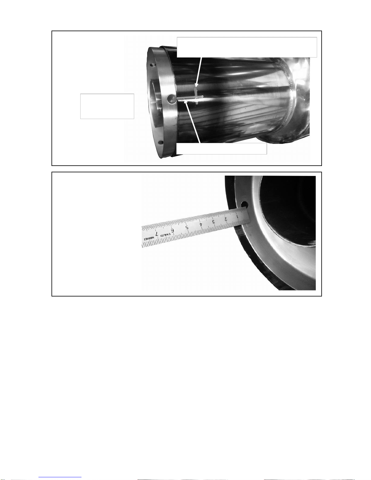
Double check the distance from the reference bolt hole to the edge/end of the exhaust tip (15mm).
3. Insert the sound reducer and mark the center point of the 2 additional bolt holes.
4.
Secure the sound reducer using the reference bolt hole together
with the included M6 button bolt and flange nut.
Check that the sound reducer is aligned correctly and that the additional bolt holes
are the same distance from the exhaust tip/end as the reference hole (15mm).
※PARTS USED: Button Bolt M6, Flange Nut M6.
Reference bolt hole
Reference bolt hole
13
5.
Using a center drill, add a pilot hole to one of the extra bolt holes marked earlier.
6.
Check to make sure it's centered then enlarge the hole to 6.5mm diameter (to fit M6 bolt).
7.
Then secure in place using the M6 button bolt and M6 flange nut.
8.
Double check the sound reducer bolt hole positioning and repeat the process for the 3rd bolt hole.
9.
After drilling all the holes, be sure to grind down any sharp edges.
10.
Clean and/or remove any remaining debris.
Sound reducer bolt hole center.
Distance from the exhaust tip edge/end to the bolt
hole (Std. 15mm. Actual measurement recommended).
Temporarily insert
the sound reducer.
MARKING THE ADDITIONAL
BOLT HOLE LOCATIONS
CHECKING THE SOUND REDUCER ALIGNMENT
(15mm from exhaust tip/end to bolt hole center)
14

3. INSTALLING THE TOMEI TITANIUM EXHAUST
【Mounting position of each component】 Install the included components as shown below.
<Positioning and torque specs. of the included components>
①MAIN PIPE A ⑨SILENCER BAND
②MAIN PIPE B ⑩SILENCER BAND RUBBER
③SILENCER ⑪FLANGE BOLT M8 L=25mm
④GASKET ⑫FLANGE NUT M8 [19.6~28.4N.m(2.0~2.9kgf-m)]
⑤FLANGE BOLT M10 ⑬SOUND REDUCER
⑥
FLANGE NUT M10
[34.3~39.2N.m(3.5~4.0kgf-m)] ⑭BUTTON BOLT M6
⑦CLAMP BAND [25.0N.m(2.55kgf-m)] ⑮FLANGE NUT M6 [7.8~11.8N.m(0.8~1.2kgf-m)]
⑧SPRING ⑯ZIP TIE
※Apply the Bolt Smooth Paste (included) to the fastenings that will be exposed to high temperatures.
This helps prevent them from becoming stuck or seized.
15

【INSTALLATION PROCESS】
1. Loosely install MAIN PIPE A using the included GASKET, FLANGE BOLT M10 and FLANGE NUT M10.
※
Parts used:
MAIN PIPE A (①, previous page), GASKET (④, previous page)
FLANGE BOLT M10(⑤, previous page), FLANGE NUT M10(⑥, previous page)
2. Attach the CLAMP BAND to MAIN PIPE B. Then, slide MAIN PIPE B onto MAIN PIPE A, making sure that
the spring hooks align.
※Parts used:
MAIN PIPE B (②, previous page), CLAMP BAND (⑦, previous page)
3. Attach the CLAMP BAND to the SILENCER. Then, slide the SILENCER onto MAIN PIPE B, making sure that
the spring hooks align.
※Parts used: SILENCER(③, previous page) CLAMP BAND (⑦, previous page)
Ensure that the SILENCER is installed with the logo facing downwards.
4.
Attach the SILENCER BAND RUBBER to the SILENCER BAND. Then, mount the SILENCER BAND
on to the exhaust hanger, taking care not to scratch the SILENCER.
※
Parts used:
SILENCER BAND (⑨, previous page), SILENCER BAND RUBBER (⑩, previous page)
5. Tighten down the fastenings in order from the font, ensuring sufficient clearance is achieved.
<Torque specs.>
FLANGE NUT M10
(⑥, previous page) [34.3~39.2N.m(3.5~4.0kgf-m)]
FLANGE NUT M8 (⑫, previous page) [19.6~28.4N.m(2.0~2.9kgf-m)]
CLAMP BAND (⑦, previous page) [25.0N.m(2.55kgf-m)]
6. Attach the SPRINGS onto MAIN PIPE A, MAIN PIPE B and the SILENCER.
CAUTION
・Ensure sufficient clearance and correct fitment has been achieved before completely tightening
down the fastenings. In some cases, there may be insufficient clearance due to minor differences
between individual vehicles. In such a case, loosen the fastenings on the catalytic converter and
adjust the positioning until sufficient clearance is achieved before retightening the fastenings again.
・Ensure you clean the exhaust after installation. Using the exhaust whilst there is oil or other debris
on it can cause blemishes and/or burn marks.
・Depending on the installation and use of the exhaust, you may need to apply thermal insulation to
prevent heat damage to the surrounding components/areas.
7 Zip tie the Muffler Hanger/Strap mounts (see right)
to prevent excessive shake.
※Parts used: Zip Ties (⑯ on previous page).
8
Install the SOUND REDUCER when necessary.
※Parts used: SOUND REDUCER (P15 ⑬), BUTTON BOLT (P15 ⑭),FLANGE NUT (P15⑮)
<TORQUE SPECS>
Button Bolt M6 【7.8~11.8N.m(0.8~1.2kgf-m)】
WARNING
・Do not drive at high speeds with the SOUND REDUCER installed
as it may become damaged and/or broken.
・Only install/uninstall the SOUND REDUCER when the exhaust is cold.
9. Re-connect the negative battery terminal.
16

4. POST INSTALLATION CHECKS
1. Check again to ensure the product is fitted correctly.
2. Start the engine. Rev to 2500rpm and check for any abnormal sounds.
3. Test drive the vehicle and check again for any abnormal sounds and/or loose parts.
WARNING
・Be thorough when performing checks as incorrect fitment and/or loose parts can lead to
accidents, reduced performance as well as damage to surrounding components.
・Exhaust leaks not only reduce performance but can also be a health hazard and should be
addressed immediately.
・If there are any abnormalities whilst using the vehicle, stop immediately and check for faults.
・Ensure all exhaust related components have cooled before attempting any repairs.
・Do not restart the engine should you notice anything abnormal such as missing/broken parts.
Instead, consult a trained professional and follow their instructions.
CAUTION
・Once this product has been installed on the vehicle, the engine characteristics may change
depending on the setup. After installation, adjust the engine/ECU settings as necessary.
17

18
18

19
19

20
13 Orchard Suite 107
Lake Forest, CA 92630 USA
TEL : +1-949-855-6577
FAX : +1-949-855-6525
OPEN: Monday - Friday (National holidays and public holidays excluded).
10:00 - 19:00 PST
http://www.tomeiusa.com
20
Table of contents
Popular Other manuals by other brands


Sams
Sams DigiKEY-1 User manual for use and maintenance

LOGOPAK
LOGOPAK Cleaning kit 5 Contents and Operating instructions

Sloan
Sloan WES-4000 installation instructions

Yamaha
Yamaha MSH-420 owner's manual

Pelican
Pelican 0450 user manual

Whelen Engineering Company
Whelen Engineering Company TIR3 installation guide


