Tometek SHI400-12 User manual
User’s Manual
Before using the inverter, you need to read and save the
safety instructions.

TNI SERIES
(SHI400, SHI600, SHI1000)
Pure Sine Wave Inverter
The information presente in this ocument oes
not form part of any quotation or contract, is believe
to be accurate an reliable an may be change without
notice.

CONTENTS
1. Intro uction ................................................... 1
2. Important Safety Instructions ........................ 2
3. Inverter Operation ......................................... 4
4. Functions ....................................................... 5
5. Troubleshooting ........................................... 12
6. Maintenance an Warranty .......................... 14
7. Technical Specification ............................... 15

1
1. ntroduction
Thanks for purchasing TNI-SHI series inverters. The pro uct is a
pure sine wave inverter which can convert 12/24/48V c to 220/230Vac
50/60Hz base on full igital an intelligent esign. It features high
reliability, high efficiency, concise outline, small volume, full protection
functions, easy installation an operation. The inverter can be applie in
many fiel s, such as househol appliances, electric tools an in ustrial
evices etc, especially for solar photovoltaic power system.
Features:
Complete isolation-type inverter technology.
A option of a vance SPWM technology, pure sine wave output.
Dynamic current loop control technology to ensure inverter reliable
operation.
Wi e DC input voltage range.
Low output harmonic istortion (THD≤3%).
LED in icators for input voltage range, loa power range, normal
output & failure state.
Optional energy saving mo e.
The output voltage an frequency can be switche .
Extensive protections: short-circuit, overloa , un er/over input
voltage, over-temperature, an inverter’s inner fault i entification
protections.
Wi e working temperature range (in ustrial level).
Continuous operation at full power.

Tometek confidential
2
2. mportant Safety nstructions
As an AC power supply equipment, the inverter’s output voltage is
with the same level as that of househol power plug. Min the AC output
terminals, or you may get an electric shock an result in life anger!
Attentions:
Connect the DC input accor ing to the requirement strictly. The
power inverter has a relatively wi e input range, but too high or too
low input may cause problems even estroy the inverter. The surge
input voltage can’t excee 20V for the 12V inverters, 40V for 24V
inverters, 80V for 48V inverters, or the inverters will be amage .
A reverse polarity connection will blow the fuses in the inverter an
may amage the unit.
Do not expose the inverter to humi , flammable, explosive or ust
environment.
Keep the inverter out of chil ren touch.
Inverter input is recommen e to connect to battery, the min.
capacity of battery(expresse in AH) shoul be calculate in the
following way: 5times of the rate power of the inverter/battery
voltage. If for testing purpose, user shoul select DC power supply
current at least twice greater than that of the inverter rate input to
keep inverter normal operation. Use DC power supply for testing
may cause the amage of the inverter.
When the inverter works continuously, its surface may became very
hot, please make sure the air ventilation clearance aroun the inverter
is more than 10cm. Keep away from the material or evice which
may suffer from high temperature when the inverter is working. Do
not install the inverter in airproof location an keep enough space
aroun the inverter.

Tometek confidential
3
The protective groun ing must be connecte to the groun . The cross
section of wire shoul not be less than 4mm
2
.
A fuse or breaker shoul be use between battery an inverter, the
value of fuse or switch shoul be twice of the inverter rate input
current.
The wire connects between battery an inverter shoul be shorter
than 3m, the current ensity shoul be less than 3.5A/mm
2
while the
output of inverter is fully loa e . If the wire longer than 3m, the
current ensity shoul be re uce .
Do not connect the battery charger or similar evices to the input
terminal of the inverter.
Do not put the inverter close to the floo e lea -aci battery because
the sparkle in the terminals may ignite the hy rogen release by the
battery.
It’s an off-gri inverter, if connect to the gri , the inverter may be
amage .
This inverter can only be use singly, parallel connection or in series
will amage the inverters.
Do not attempt to repair the fault inverter yourself, otherwise it may
lea to a serious acci ent. Please contact the manufacture’s engineer.

Tometek confidential
4
3. nverter Operation
Connect the input an output terminals accurately. Turn on the
power using the ON / OFF switch on the front panel. In or er to avoi the
protections resulte from the surge power, please turn on AC loa s one by
one after the output of the inverter is normal. Please check it as below:
Set the power switch to the ‘OFF’ position. Insert the loa ’s plug into
the inverter’s output outlet.
Connect the protective groun ing to the groun .
Make sure the fuse or breaker use between battery an inverter is off.
Connect the battery (‘+’ terminal with re line, ‘-’with black line). Do
not connect them by contraries, or the power inverter will be
amage .
Switch on the fuse or breaker. Switch the inverter to ON an then
turn on the loa s one by one. Check the operation state of both power
inverter an loa s. ‘Green’ of the failure LED in icator means the
state is normal.
If there are ifferent loa s, it is suggeste that turn on the loa with
large startup current first, such as television, then turn on the loa
such as lamp when the inverter works stable.
If the failure LED in icator is ‘Re ’ an the buzzer alarms or no
output when you turn on evices, switch off the loa s an power
inverter imme iately. Check the system by referring to the
troubleshooting gui e. Turn on the evices again accor ing to the
operation metho s after the failure is remove .
Tometek confidential
5
4. Functions
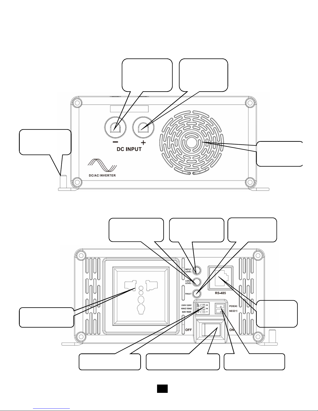
DC nput Panel
AC Output Panel
Protective
Groun ing
Fan
Ventilatio
n
DC Input
Terminal
N
egative
DC Input
Terminal
P
ositive
Fault
In icator
AC Outlet
ON/OFF
Switch
Switch
No e
RS485
Port
Input
Level
In icator
Loa
Level
In icator
Mo e
Switch

Tometek confidential
6
The Optional Outlet
Australia/New Zealand
European

Tometek confidential
7
nput Level: Display nput Voltages
LED Status 12V 24V 48V
RED Slow Blink <10.5 <21 <42
RED 10.5~11 21~22 42~44
ORANGE 11~12 22~24 44~48
GREEN 12~14.5 24~29 48~58
ORANGE Fast Blink 14.5~16 29~32 58~64
RED Fast Blink >16 >32 >64
Load Level: Display AC Loads
LED Status AC Loa
ORANGE <20%
GREEN 20%~75%
RED >75%
RED Slow Blink Overloa
RED Fast Blink Short Circuit
Output & Fault Status
LED Status Status
GREEN Output Normal
RED Fast Blink Overloa or Short circuit, No Output
RED Slow Blink Over or Low input voltage, No Output
ORANGE Fast Blink
Over temperature, No Output
ORANGE OR RED Inverter Fault, No Output
OFF Saving mo e, Power Off,No Output

Tometek confidential
8
Alarms
Alarms Status
Buzzer Soun s
Overloa or Short circuit, No Output
Over or Low input voltage, No Output
Over temperature, No Output
Inverter Fault, No Output
The buzzer stops after 20S.
Tometek confidential
9
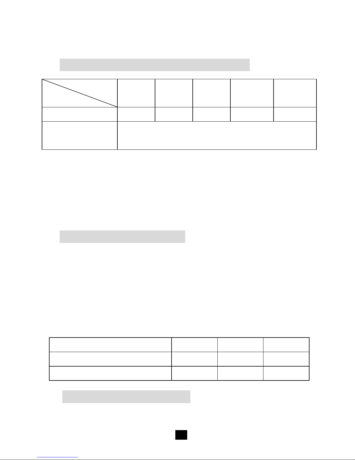
Protections
Overload or Output Short Circuit Protection
Overloa
Character 125%
150%
200%
230% >250%
Continuance 60S 10S 1.5S <0.2S <0.01S
Recover 3 times
Space 5 secon s for the first time, 10 secon s for
the secon time, an 15 secon s for the thir time
If the overloa or short circuit status still remains when the inverter
tries to recover for 3 times, you shoul re uce or clear the loa s an then
restart the inverter manually. Loa over than 250% will be treate as
output short circuit.
Input Low Voltage Protection
The output is switche off when the input voltage is lower than low
voltage protect value, an auto-switche on when the input voltage reach
low voltage recover value. User can also manually restart the inverter to
switch on output by the ‘ON/OFF switch’, when the input voltage is
higher than low voltage protect value.
12V 24V 48V
Low Voltage Protect Value 10.8 21.6 43.2
Low Voltage Recover Value 12.5 25 50
Input Over Voltage Protection
The output is switche off when the input voltage is higher than over

Tometek confidential
10
voltage shut off value, also the output is auto-switche on when the input
voltage rops below over voltage recover value.
12V 24V 48V
Over Voltage Shut Off Value
16 32 64
Over Voltage Recover Value
14.5 29 58
Fault Protection
The inverter will shut own when the output voltage is error or when
the inverter has inner fault.
Over Temperature Protection
The inverter will shut off when the internal temperature is
overheating. An it automatic restarts when the temperature recovers to
the normal level.
Others
Saving Mode
When the switch is on “Saving” si e, the inverter will enter into the
Saving Mo e. It will shut off the output if the loa s value is less than
20VA. Then restart an etect the power of the loa again after 10s. If the
loa is more than 20VA, the inverter will turn on the output .Otherwise it
will shut off output again. It cycles like this. So please on’t use the
saving mo e if the loa is smaller than 20VA.

Tometek confidential
11
Mode Switch
The output mo e can be change by the mo e switch. When the
switch No.1 is on the ON si e, the inverter will enter into the saving
Mo e. This mo e can be switche online.
When the switch No.2 is on the ON si e, the output frequency is
60Hz,otherwise is 50Hz. When the switch No.3 is on the ON si e, the
output voltage is 230Vac, otherwise is 220Vac. Both the output frequency
an the output voltage change availability after restart the inverter.
Switch Node
The inverter can be control by the other equipment through the
switch no e. When the switch no e is link, it equal to ON/OFF switch is
on. The connection between the switch no e an the ON/OFF switch as
follow iagram:
If nee to use the switch no e, a relay shoul be use . The rating
current of the relay shoul not be less than 5A. The cross section of wire
nee s 1mm
2
.

Tometek confidential
12
5. Troubleshooting
WARN NG:
High voltage is inside the inverter, do not open or disassemble
it! Attempting to service the unit yourself may cause the risk of
electrical shock or fire!
Problem Possible Cause
Solution
Input LED blink,
fault re LED slow
blink
Input voltage is
too high or too low
Measure the input voltage.
The inverter recovers when
the input becomes normal.
Loa LED blink,
fault re LED fast
blink
Overloa or loa
short
Check out if the AC loa is
within the rate power or
whether there is loa short.
Fault orange LED
fast blink
Over temperature
insi e the inverter
Improve the quality of
ventilation an o not
block the vent. Restart the
inverter when it is cool
own.
Fault re LED Inverter abnormal Remove all the connecte
plugs then restart. If
inverter works well, please
check the loa an line. If
the LED keeps re , the
inverter has insi e faults
an shoul be returne to
the factory.

Tometek confidential
13
Fault orange LED Inverter abnormal Ma e sure the DC input
terminals is tight, the input
voltage between 10.8V an
15V (21.6~30V for 24V,
43.2~60V for 48V pro uct)
an restart the inverter. If
the LED keeps orange the
inverter has insi e faults
an shoul be returne to
the factory.

Tometek confidential
14
6. Maintenance and Warranty
The casing of the inverters may be cleane regularly with a amp
cloth (not wet) to prevent accumulation of ust an irt. The screws on
the DC input terminals must be tightene .
The warranty perio of the inverter is 2 year since the ate of
original shipping. Within the perio , we will repair the pro uct or replace
the efective pro uct for free. Return the efective with shipping cost
prepai . An provi e proof of purchasing ate. We will pay the return
shipping charges within warranty perio .
The warranty oesn’t apply un er the following con itions:
1. Damage by acci ent, negligence, abuse, improper use
2. Input voltage excee the nominal input voltage of inverter
3. Unauthorize mo ification or attempte repair
Tometek confidential
15
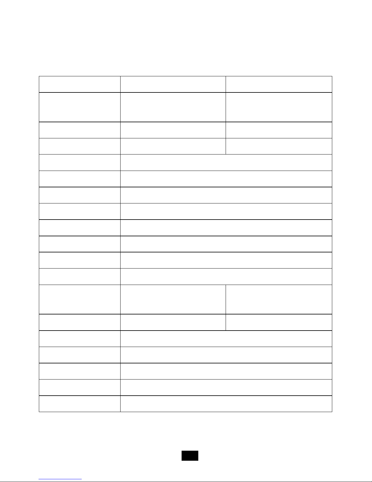
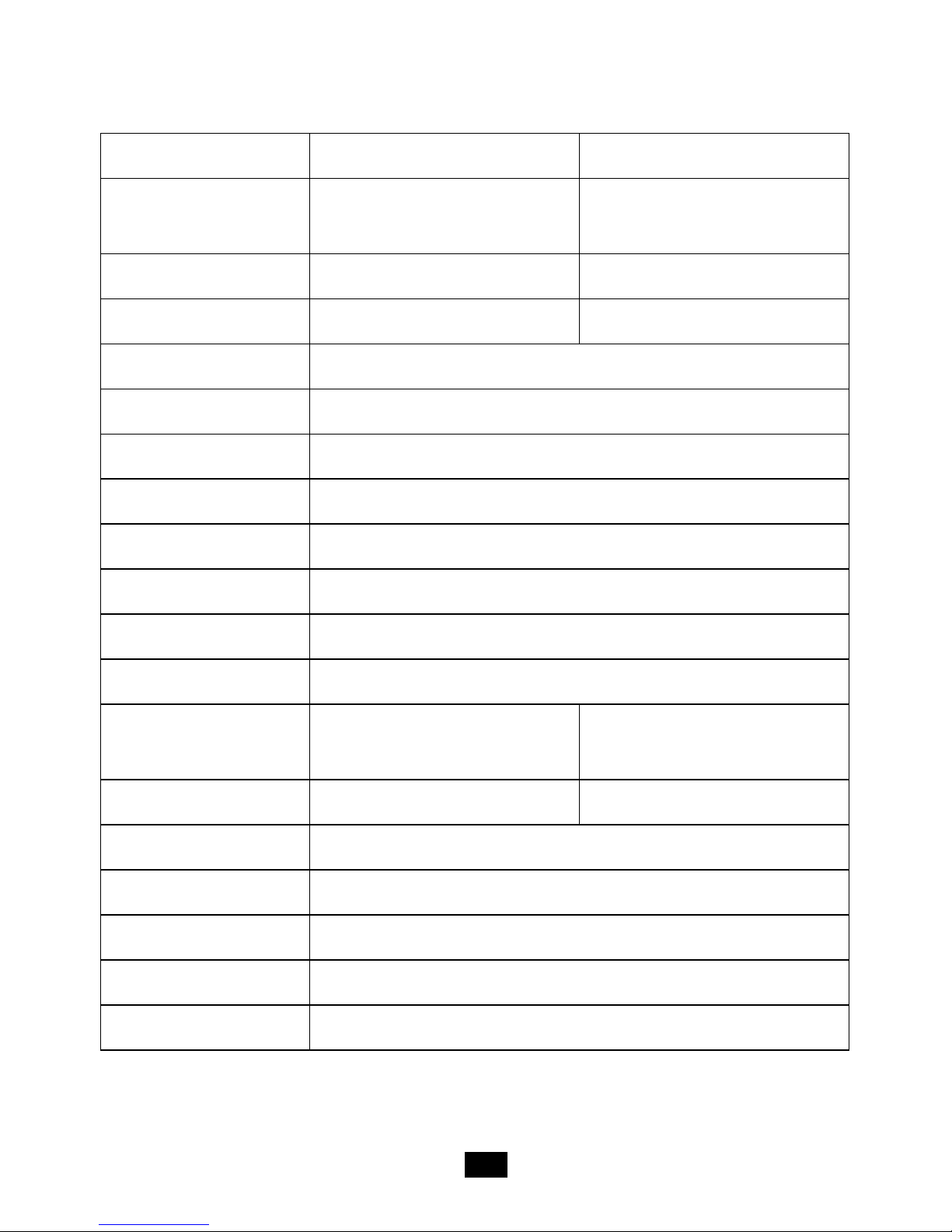
7. Technical Specification
Technical Data
Types SHI400-12 SHI400-22
Nominal Battery
Voltage 12V 24V
Input Voltage Range
10.8 ~16V c 21.6 ~32V c
No Loa Current ≤0.8A ≤0.45A
Output Wave Pure Sine Wave
Output Voltage 220Vac±3% / 230Vac±10%
Continuous Power 400W
Power 10 sec 600W
Power 1.5 sec 800W
Surge Power 900W
Frequency 50/60Hz±0.2%
Distortion THD ≤ 3%( resistive loa )
Efficiency at Rate
Power ≥91% ≥92%
Max. Efficiency ≥92% ≥93%
Terminal 16mm
2
Dimensions 280×166×74.3mm
Installation 150×158mm
Hole Size Φ5mm
Net Weight 1.8kg

Tometek confidential
16
Types SHI600-12 SHI600-22
Nominal Battery
Voltage 12V 24V
Input Voltage Range
10.8 ~16V c 21.6 ~32V c
No Loa Current ≤0.7A ≤0.45A
Output Wave Pure Sine Wave
Output Voltage 220Vac±3% / 230Vac±10%
Continuous Power 600W
Power 10 sec 900W
Power 1.5 sec 1200W
Surge Power 1350W
Frequency 50/60Hz±0.2%
Distortion THD ≤ 3%( resistive loa )
Efficiency at Rate
Power ≥91% ≥92%
Max. Efficiency ≥93% ≥94%
Terminal 25mm
2
Dimensions 295×186×82mm
Installation 150×178mm
Hole Size Φ6mm
Net Weight 2.3kg
Tometek confidential
17
Types SHI1000-22 SHI1000-42
Nominal Battery
Voltage 24V 48V
Input Voltage Range
21.6 ~32V c 43.2 ~64V c
No Loa Current ≤0.45A ≤0.35A
Output Wave Pure Sine Wave
Output Voltage 220Vac±3% / 230Vac±10%
Continuous Power 1000W
Power 10 sec 1500W
Power 1.5 sec 2000W
Surge Power 2250W
Frequency 50/60Hz±0.2%
Distortion THD ≤ 3%( resistive loa )
Efficiency at Rate
Power ≥93% ≥93.5%
Max. Efficiency ≥94% ≥94%
Terminal 25mm
2
Dimensions 295×208×98mm
Installation 150×200mm
Hole Size Φ6mm
Net Weight 3.3kg
This manual suits for next models
5
Table of contents


