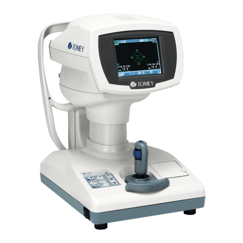
Tomey RC-5000 User manual

OPERATOR MANUAL
AUTO REFKERATOMETER
RC-5000
Read this operator manual completely before attempting to use this instrument in
order to operate it properly and safely.
Do not use procedures other than those specified in this manual.
Keep this operator manual in a place you can access easily.
If you lose this operator manual, contact your Tomey representative.
Contact your Tomey representative if you have any questions or problems.


i
To the User of the RC-5000 AUTO REFKERATOMETER
The RC-5000 AUTO REFKERATOMETER is especially designed for measuring eye's re-
fractive power and corneal curvature.
The RC-5000 provides the additional functions of PD, corneal diameter, pupillary diameter,
and CL base curve measurements. Since, however, the measurement quality of these func-
tions is not guaranteed, the exclusive equipment designed for respective measurements
should be used.
TO THE USER OF THE RC-5000 AUTO REFKERATOMETER

ii
CAUTION LABELS
Do not stain or damage the caution labels.
If the caution label is stained or damaged, ask Tomey Corporation or
your local distributor or representative for its replacement.
CAUTION LABELS

iii
THE STRUCTURE OF THIS OPERATOR MANUAL
The structure of this Operation Manual is as follows.
1. PRIOR TO USE
Precautions and confirmations for the installation and usage
of the instrument.
2. NAMES AND FUNCTIONS OF THE COMPONENTS
Names and functional descriptions of the components.
3. OPERATING PROCEDURE
Vital information needed for installing and using of the in-
strument.
4. REFERENCE TECHNICAL INFORMATION
Useful technical information for your operation.
5. INSPECTION AND MAINTENANCE
Routine replacement of spare parts, routine maintenance and
inspections.
6. TROUBLESHOOTING
How to remedy problems.
7. SUPPLIES (Available separately)
Available at option.
8. SPECIFICATIONS
Specifications for this instrument.
THE STRUCTURE OF THIS OPERATOR MANUAL

iv
SYMBOLS USED IN THIS OPERATOR MANUAL
The symbols used in this manual represent the following meanings.
Precaution that, if unheeded will cause a hazardous situa-
tion where there is imminent danger of serious injury or
death.
Precaution that, if unheeded, will cause a hazardous situ-
ation where there is possibility of serious injury or death.
Precaution that, if unheeded, will cause a situation where
there is a possibility of minor or moderate injury or dam-
age to property.
Special precaution suggested by Manufacturer that either
directly or indirectly relates to the safety of personnel or
to the protection property.
SYMBOLS USED IN THIS OPERATOR MANUAL

v
CONTENTS
CONTENTS
1. PRIOR TO USE ............................................................................................................. 1-1
1.1 SAFETY PRECAUTIONS ............................................................................................................... 1-1
1.2 Unpacking ....................................................................................................................................... 1-4
1.3 GLOSSARY .................................................................................................................................... 1-5
1.4 Outline of operations....................................................................................................................... 1-7
2. NAMES AND FUNCTIONS OF THE COMPONENTS .................................................. 2-1
2.1 EXAMINER'S SIDE ......................................................................................................................... 2-1
2.2 PATIENT'S SIDE ............................................................................................................................. 2-3
2.3 MEASUREMENT SCREEN ............................................................................................................ 2-4
2.4 OPERATING PROCEDURES OF THE JOYSTICK ......................................................................... 2-7
2.5 TOUCH ALIGNMENT ...................................................................................................................... 2-8
2.6 RS-232C CONNECTOR .................................................................................................................. 2-8
3. OPERATING PROCEDURES ....................................................................................... 3-1
3.1 INSTALLING .................................................................................................................................... 3-1
3.1.1 Precautions for installing place ..................................................................................... 3-1
3.1.2 Precautions for connecting of the Power Cord ............................................................ 3-2
3.1.3 Checking of the printer paper ....................................................................................... 3-2
3.2 PREPARATION FOR MEASUREMENT .......................................................................................... 3-3
3.2.1 Starting of instrument operation .................................................................................... 3-3
3.2.2 Selecting of the measurement mode and setting of the measuring conditions .......... 3-4
3.2.3 Adjusting of Patient's position ...................................................................................... 3-5
3.2.4 Alignment procedure .................................................................................................... 3-6
3.3 MEASUREMENT ............................................................................................................................ 3-8
3.3.1 Refractive power measurement mode ......................................................................... 3-8
3.3.2 Corneal curvature (keratometer) measurement mode ................................................ 3-11
3.3.3 Refractive power and corneal curvature (refkeratometer) measurement mode .........3-13
3.3.4 Corneal diameter and pupillary diameter measurement mode ..................................3-14
3.3.5 Contact lens measurement mode ...............................................................................3-15
3.4 PRINTOUT .....................................................................................................................................3-16
3.4.1 Printing-out procedures ............................................................................................... 3-16
3.4.2 Print mode ................................................................................................................... 3-17
3.5 DISPLAY OF MEMORY DATA ....................................................................................................... 3-20
3.6 DATA MANAGEMENT WITH "TOMEY Link" .................................................................................. 3-21
3.6.1 Setup............................................................................................................................3-21
3.6.2 Receiving of Patient's ID..............................................................................................3-22

vi CONTENTS
3.6.3 Sending of measurement data ....................................................................................3-23
3.7 ID INPUT WITH TOMEY FORM......................................................................................................3-24
3.8 SETUP OF MEASUREMENT CONDITIONS ..................................................................................3-25
3.8.1 Setup............................................................................................................................3-25
3.8.2 Temporary Setup .........................................................................................................3-32
3.9 LANGUAGE SELECTION ..............................................................................................................3-34
4. REFERENCE TECHNICAL INFORMATION ................................................................ 4-1
5. INSPECTION AND MAINTENANCE ............................................................................. 5-1
5.1 WARRANTY .................................................................................................................................... 5-1
5.2 LIFE OF PRODUCT ........................................................................................................................ 5-2
5.3 INSPECTION ................................................................................................................................... 5-2
5.4 ROUTINE MAINTENANCE .............................................................................................................. 5-3
5.5 REPLACING OF SPARE PARTS .................................................................................................... 5-4
5.5.1 Replacing of the Printer Paper ..................................................................................... 5-4
5.5.2 Replacing of the fuse .................................................................................................... 5-5
5.5.3 Replacing of the Chin Rest Paper ................................................................................ 5-5
5.6 STORING ........................................................................................................................................ 5-6
5.7 DISPOSAL OF PACKING MATERIALS........................................................................................... 5-7
6. TROUBLESHOOTING.................................................................................................. 6-1
7. SPARE PARTS ............................................................................................................. 7-1
8. SPECIFICATIONS......................................................................................................... 8-1
8.1 SPECIFICATIONS ........................................................................................................................... 8-1
8.1.1 Refractive power measurement .................................................................................... 8-1
8.1.2 Corneal curvature measurement ................................................................................... 8-1
8.1.3 Pupillary distance measurement .................................................................................. 8-2
8.1.4 Corneal diameter and pupillary diameter measurement .............................................. 8-2
8.1.5 Observation range ........................................................................................................ 8-2
8.1.6 Auto-alignment range .................................................................................................... 8-2
8.1.7 Main unit ........................................................................................................................ 8-2
8.1.8 Power source ............................................................................................................... 8-2
8.2 NOISE OCCURRENCE ................................................................................................................... 8-3
8.3 ENVIRONMENTAL CONDITIONS .................................................................................................... 8-3
8.4 REGULATORY COMPLIANCE ........................................................................................................ 8-3
8.5 EMC COMPATIBILITY DECLARATION ............................................................................................ 8-4

1-1
1. PRIOR TO USE
Please read this Operation Manual throughout before
operating this instrument.
Do not use any procedures other than specified in this
Manual.
1.1 SAFETY PRECAUTIONS
The following precautions shall be given for installing this
instrument.
- Do not install the instrument in a place where any chemicals are
stored or any gas is generated, or it may otherwise be inflamed to
catch a fire, if such chemicals or gas is spilled or evaporates into
the inside of the instrument.
- Do not lift the instrument by holding the Chin Rest or the Head
Rest, which may otherwise cause the instrument to slip to fall
down and possibly harm you.
- Make sure that the frequency, voltage, allowable current (or
consumption power) of your power source used for the
instrument are proper. The wrong power, if used, may cause
inflammation or electric shock.
- Properly connect the grounding wire, which may otherwise cause
struck by electricity.
- Do not place a heavy object over the power cord nor squeeze it
with undue force, or it may cause inflammation or electric shock.
- Be sure to securely connect the power cord with the instrument.
The power cord, if improperly connected in contact failure, with
the metallic part, or with the exposed plug terminal covered with
dust, may cause inflammation or electric shock.
- Do not connect the instrument to any equipment of which data
transfer code is different from that for this instrument. Which may
cause inflammation or struck by electricity. In case of connecting
this instrument to the communication connector, be sure to
consult with Tomey Corporation.
1.1 SAFETY PRECAUTIONS

1-2
- Install the instrument in a place where it is not exposed to water
and / or chemicals. In case Water and / or chemicals enter into
instrument, it may cause struck by electricity or malfunction.
- Install the instrument in a place where it is fear free of adverse
influences by direct sunbeams, high temperature, high moisture,
dust, salt, sulfur contained air, which may otherwise cause the
instrument with malfunction or erroneous operation.
- Install the instrument in a stable place where it is free of
inclination, vibration and/or shocks, which may cause incorrect
measurement, tilting, or falling, possibly resulting in inflammation
or physical injury.
Sufficient care shall be taken on the following items while
operating the instrument.
- In the event the instrument causes smokes, odors, or abnormal
noises, immediately turn the power off, disconnect the power
plug from the receptacle, and then report so to your local
distributor, representative, or Tomey Corporation.
- Pay attention and carefully to the position of Patient's face and
hand or fingers ,When operating Measurement Head and Chin
rest. It may cause physical injury depend on movement of
Measurement Head and Chin rest.
- Advise the Patient not to place his hand and fingers in the under
space of the Measurement Head or below Chin rest, which may
otherwise cause his hand and fingers to be pinched and harmed.
- Do not either lean or compress the instrument, which may
otherwise cause its fall or malfunction, or personal injuries.
- Do not place or leave any liquid contained bin or container on the
instrument, which may cause struck by electricity or
malfunctions.
- Do not touch the Printer paper cutter with your fingers, which may
cut yourself.
- Before measuring the next Patient, remove the top sheet of
paper from the Chin Rest and clean the Head Rest with clean
cloth. Also, clean the Head Rest and the Chin Rest with
sterilization alcohol-soaked cloth for sterilization.
1.1 SAFETY PRECAUTIONS

1-3
Care shall be taken on the following items, after using the
instrument.
- Do not use organic solvents, such as thinner, benzene, and
acetone, for cleaning the instrument, which may cause
inflammation or struck by electricity.
- Do not apply an undue force to the power cord when
disconnecting from the receptacle, but hold the plug unit instead.
If the cord is forcedly pulled, the core wire inside of the cord may
be broken, causing struck by electricity or inflammation.
If the instrument is suspended for a long period of time,
disconnect the power cord from the receptacle for safety.
When the instrument is malfunctioned, discontinue its
operation and display such failure. Then, ask your distributor
for repair.
- Do not remodel or modify this instrument, which may disorder the
functions and/or cause of struck by electricity or malfunctions. It
should also be noted that the instrument provides the high
voltage generating source inside its unit which may induce struck
by electricity, if touched, causing fatal injuries or death to the
worst.
- Replacement of the fuse shall be performed with the power cord
as being disconnected from the receptacle, which may otherwise
induce struck by electricity, serious injury or death to the worst.
- If the instrument has not been used for a long period of time,
make sure before reuse that it works properly and safely. As for
the procedure of its confirmation, see "5.4 ROUTINE
MAINTENANCE" of this Manual.
1.1 SAFETY PRECAUTIONS

1-4 1.2 UNPACKING
1.2 UNPACKING
After unpacking, make sure that you have received the fol-
lowing items without damages. In the event that any item is
found missing or damaged, contact your local distributor.
The packing box and the cushion materials should be
kept, since they may be necessary, if the instrument is
moved or transported to other places.
zz
zz
zMain unit
zz
zz
zPower cord ..................................................................1
zz
zz
zModel eye ....................................................................1
zz
zz
zFuse ............................................................................4
(Two fuses have already been mounted in the main unit.)
zz
zz
zChin Rest paper ..........................................................1
zz
zz
zChin Rest paper fixing pin ...........................................2
zz
zz
zBuilt-in Printer paper roll..............................................3
(One roll has been mounted. in the Main Unit.)
zz
zz
zCL holder .....................................................................1
zz
zz
zDust cover ...................................................................1
zz
zz
zOperator Manual (This book) ......................................1

1-5
1.3 GLOSSARY
[A/AX/AXIS] Astigmatism axial angle [0° to 180°] Represents the angle of
astigmatismatwhichthe powerislocated inthedirection crossing
theastigmatismaxis.
[AA] Auto-alignment.
[AS] Auto shot.
[AVG] Average of strong and weak principal meridians.
[BC] Contact lens inner curvature (base curve) [mm]
[C/CYL] Cylindricalpower[D]
[CAT MODE] Cataract mode at the time of refractive measurement.
[CL MODE] Measuring mode for hard contact lens base curve.
[CL DATA] First prior selection of base curve by contact lens brand on the
basis of refkerato-data, which is useful for selection of reference
triallens.
[CORNEA] Representscornealdiameterinthecornealdiameterandpupillary
diametermeasurement[DIA]mode.
[IOL MODE] IOLmeasuring modeatrefractivemeasurement.
[K1] Weak Principal meridian [mm or D]
[K2] Strong Principal meridian [mm or D]
[P] Contact lens power.
[PD] Pupillarydistance[mm]
[PUPIL] Represents the pupillary diameter in the corneal diameter and pu-
pillarydiametermeasuring[DIA]mode.
[RA] Residualastigmatism(See[Residualastigmatism])
[S/SPH] Spherical power [D]
[Temporary] Changes measurement conditions temporarily.
1.3 GLOSSARY

1-6
[VD] Vertex distance [mm], which represents the distance between the
corneal vertex and the posterior of the corrective lens to be pre-
scribed. (When VD=CL is displayed, calculation is made for a
corneal vertex distance of "0").
[AUTO SHOT] Functionbywhichmeasurementisautomaticallystartedwhenfo-
cusinginthedirectionsofup/down/left/rightbecomesoptimum.
[AUTOALIGNMENT] Functionbywhichalignment inthe up/down/left/rightdirections
andthefocusingdirection isautomaticallymade.
[AUTO POWER OFF FUNCTION]
The LCD screen is automatically ceased if operation is sus-
pended for a specified period of time, with the power lamp as
being left flickering. (Auto Power-Off Mode) Pressing of
whichever button returns the screen to the initial operation
screen.
[HIGH-SPEED MODE] DoingAutomatic fogging atthetimestartingrefractive measure-
mentandcontinuemeasurementbymaintainingthefoggingcondi-
tion, which is useful for measurement of a Patient who has un-
stableeyefixation.
[AUTOFOGGING] Target is automatically moved to the far sighted side to provide
fogging,whicheliminatesPatient'seyeadjustment.
[TOUCHALIGNMENT] Touching of the target bright spot in the screen moves the measur-
ing head to position the target bright spot to the center of the
screen. Alignment can be made without operating the Joystick.
[TOUCH PANEL] Directly touching of the Monitor enables various operations as
wellastouchalignment.
[RESIDUALASTIGMATISM] This implies a residual astigmatism which is calculated by
assumedly having the Patient wear a virtual hard contact lens,
which may differ the value from that for simple astigmatism
orcornealastigmatism.
[SPHERICAL EQUIVALENCE] Calculated with refractometry values, SPH + CYL/2
1.3 GLOSSARY

1-7
1.4 OUTLINE OF OPERATIONS
The Auto Refkeratometer, RC-5000, is an objective refractive power
measuring instrument which provides the ophthalmometry function to
measure corneal curvature.
The Patient places his chin on the Chin Rest and looks the fixation target
through the measurement window. The examiner adjusts the focusing di-
rection by moving the Joystick up/down/left/right. After this adjustment
above, press the measurement button to start measurement.
This instrument also provides the Auto Alignment mechanism for auto-
matic alignment; therefore, easy measurement operation is obtainable. In
addition, the instrument provides the Auto Shot function which automati-
cally starts measurement when the instrument enters in the area of mea-
surement. Once automatic measurement starts, the infrared light is pro-
jected for measurement to analyze the refractive power and the corneal
curvature of the eye.
Measurement data is printed out by pressing the Print button.
1.4 OUTLINE OF OPERATIONS

1-8
This page is intentionally blank

2-1
2. NAMES AND FUNCTIONS OF THE COM-
PONENTS
2.1 EXAMINER'S SIDE
$MEASUREMENT HEAD
Part where measurement is performed.
%MONITOR/TOUCH PANEL
The Measurement screen and various setting screens are displayed. Various settings and
operations are also performed by pressing of the touch panel buttons provided in the liquid
crystal monitor. (See Section 2.5.)
&JOYSTICK
The Measurement Head is adjusted up/down/left/right with the Joystick. (See Section 2.5.)
'MEASUREMENT SWITCH
Measurement is started with this switch.
(UP/DOWN ADJUST RING
The Measurement Head is rough adjusted by up and down the Ring. Slight adjusted by
turning the Ring. (See Section 2.4.)
2.1 EXAMINER'S SIDE
Ԙ
ԙ
Ԛ
ԛԜ
ԝ
Ԟ
ԟ
Ԡԡ
Ԣ
Ԣ
ԣ
Ԥ
Ԩ
ԥ
Ԧ
ԧ
ԩ
Ԫ

2-2 2.1 EXAMINER'S SIDE
)HAND REST
The Hand Rest is used to place the hand while it is used to turn the Joystick. The Hand Rest
is also used for roughly adjusting the Measurement Head front/rear/left/right. (See Section
2.4.)
*PRINTER
Prints measurement results.
+EYE LEVEL MARK
The level of the patient's eye to be measured is adjusted to this mark.
,RS232C CONNECTOR
This Connector terminal is used to connect external equipment to this instrument. (See "2.6
RS-232C CONNECTOR".)
-SERVICE MODE SELECT SWITCH
This Select Switch is used for version-up of the software.
.CLEAR BUTTON
Measurement data are deleted with this button.
/MODE BUTTON
The measurement mode is selected.
0PRINT BUTTON
Starts the printing.
1AUTO BUTTON
Changes over Auto Measurement or Manual measurement.
2IOL/CAT BUTTON
When Refractive measurement, the IOL mode or the CAT mode is changed over.
3DATA Link BUTTON
Sends out the measured data into a computer etc.
4PACKING BUTTON
The Measurement Head is moved to a place which is appropriate for packing.
5CHIN REST BUTTON
The Chin Rest rises by pressing the "S" Button and lowers by pressing the "T" button.
6POWER LAMP
The Power Lamp lights up while the Power is on.

2-3
2.2 PATIENT'S SIDE
$MEASUREMENT WINDOW
The Patient looks at the fixation target through the Measurement Window.
%CHIN REST
Patient's chin is placed on the Chin Rest.
&HEAD REST
Patient's forehead is placed to the Head Rest.
'POWER SWITCH
The power is turned on by pressing the side of " I (ON)" and turned off by pressing the side
of " O (OFF)".
(POWER CONNECTOR
The power cable is connected to the Power Connector.
)FUSE HOLDER
The fuse is placed in the Fuse Holder.
*FIXATION TARGET
Fixation target is in the measurement window. Leading Patient's eye fixation.
Ԙ
ԙ
Ԛ
ԛ
Ԝ
ԝ
Ԟ
2.2 PATIENT'S SIDE

2-4
2.3 MEASUREMENT SCREEN
Ԙ
ԙ
Ԛ ԛԜ
ԝԞԠ
ԡԢ
ԣԤ
ԥԦ
ԧ
Ԩ
ԩ
Ԫԫ
ԥ
ԟ
$MEASUREMENT MODES DISPLAY "RK" / "REF" / "KRT" / "DIA" / "CL"
Measurement modes (Ref-keratometer "RK" / Refractometer "REF" / Keratometer "KRT"
/Corneal diameter·Pupil diameter "DIA" / Contact lens base curve "CL" are displayed.
%EXAMINATION EYE DISPLAY BUTTON "R" / "L"
The Right or Left side of eye being examined is displayed in color. If pressing of this
Button when changing to the other side examination eye, largely moves the Measurement
Head.
&IDENTIFY NUMBER "No."
The identify number is displayed. "1" is added to the previous identify number for the new
measurement.
'VERTEX DISTANCES "CL" / "12.0" / "13.5" / "14.0" / "15.5" / "16.0"
The distance between cornea vertex and corrective lens posterior is displayed. (Unit: mm)
"CL" represents vertex distance (VD) of 0mm.
2.3 MEASUREMENT SCREEN
Table of contents
Other Tomey Measuring Instrument manuals
