Tony Ray’s DH.53 Humming Bird User manual

DH.53 Humming Bird Manual
DH.53 Humming bird- Kit Inventory
•
Wood Part: Balsa wood Sheets x5; Basswood Sheets x 1
•
Hardware Part: Carbon rod x 1; Micro Hinge x 1; Micro screw x 16; Rubber wheel x
; Heat shrink tube x 1; Mini Magnet x 6
•
Paper Part: Installation drawings x ; Covering tissue x 1
Required Electronics (available from teve Webb Models)
•
Motor: 8.5mm coreless motor with gearbox
•
Propeller: 5.5in or 138mm prop /LiPo battery
•
RC Transmitter with at least 4 channels
•
Receiver board with servos
•
1.7g Micro servos for the ailerons

This is a small model but don’t underestimate its complexity. It is suggested that this
should not be a first build of a model aircraft. Some prior knowledge would be
helpful. However, I’ve tried to point out any pitfalls and ease the way to making a
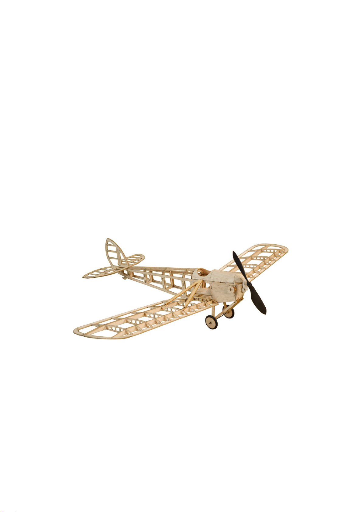
successful model of the DH53 Humming Bird.
1. Before you start
oSome items you may find helpful
•A sharp, fine modelling knife or scalpel and additional blades
•Fine nosed pliers or strong tweezers
•A very fine cross head screw driver for miniature screws
•A couple of clear plastic containers for holding small parts. Keep your clear
plastic, takeaway food containers, they’re ideal.
•Pins and a small building board.
•In the main it is recommended to use thin cyano acrylate (super glue) for the
well-fitting joints and thinly spread aliphatic resin (yellow glue) for sheet to
sheet bonds
•A capillary tube extension for the cyano acrylate bottle to reach awkward glue
joints
•A small sanding board (make one by gluing pieces of 1/16 balsa, 3inch x
1. 5inch with grain crossed at 90deg. You can stick a different grade of
sandpaper to each side to make a really handy small sanding block)
•A flat building board which can take pins to build on. A5 size is adequate but
somewhat larger will give more room for tools etc.
oRead through this help sheet in conjunction with the pictorial build document.
oThere are 6 small circular magnets in the kit. To ease things later on, mark them all on
the same pole before you start. I found the easiest way was to put them all together and
mark one magnet face with a “sharpie” pen. Then remove that magnet and mark the
next one… and so on. This means that you can easily identify which way round they
need to be during the build.
oCheck each “Step” before you start it. Study the photos in the pictures
oIdentify all the parts for each step and remove only these from the relevant sheet by
cutting through the tabs in the laser cuts around each item. Use a plastic container to
hold them until needed in the step.
oAny offcuts containing other pieces (like the centre of a former etc.) can be stored in
another plastic container
oRemember, the parts are extremely small and leave very little room for recovery if you
get things wrong. However, the standard of the kit makes it less likely that you will make
that mistake in the first place.

2. The build
Not all of the steps need clarification; this does not mean they aren’t important.
Make sure you check them as you go through the build.. Read the instruction sheet
in conjunction with the illustrations or “Steps”.
The Fuselage
There is no plan sheet for the fuselage as it is not necessary. The fuselage parts fit
together and are practically self-jigging, you may need to use a right angle to ensure
some parts are square, in an emergency, a CD case works well.
Steps 1 and 2
•Select the parts as shown to build the fuselage sides
•Make sure to make opposite sides as shown but do not remove the
lightening holes yet
•Use the 1mm (narrow) strips for the edges and glue absolutely flush with the
edges
•Strips run from the front to just short of the rear dotted line. Leave a gap the
thickness of the strip for the rearmost former
Steps 3 and 4
•Select the parts shown. Fit the basswood formers with the side arms first,
making sure they are at right angles to the sides.
•Fit the front basswood former then work towards the rear, all the time
checking the fuselage is aligned accurately
Step 5 and 6
•Remove the forward deck from the basswood sheet.
•Take 3 of the mini magnets and if you marked the poles as suggested in the
“Before you Start” section, press them in place with the poles all to the same
side. Glue in place
•Fit the deck between the sides and fitted into the slots on the top edge.
Steps 7 to 9
•Remove the tail filler pieces and glue in place, gently cracking the sides
along the dotted line. Make sure the sides meet accurately at the rear and
that the end is exactly on the centre line
•The tail filler piece with the larger slot goes to the top

Steps 10 and 11
•Take 7 of the 1mm strips for the top rear stringers
•Glue the centre one in place, starting at the rear basswood former and
finishing butted on the top of the rear former.
•Fit the outer ones next fitting them into the slots against the sides in the rear
former
•The last 4 should be fitted with the inner first, fitted so that the rear sits
against the middle stringer and then the last pair against these at the back
and overlapping the outer ones.
Steps 12 to 17
•Remove the nose block parts from the small sheet and glue together making
sure the top edges are perpendicular so that there is a right angle at the top
rear. When dry, remove the centre sections as shown
•When this assembly is dry, glue in place under the front of the top deck
•Carefully carve and sand to shape
Steps 18 and 19
•Get together the upper deck, 3 formers and instrument panel as well as the
remaining 3 mini magnets
•Press the magnets in place with the same poles showing and glue in place
•Before gluing the formers, place the upper deck on top of the front fuselage
so that it is attracted to the magnets. Make a mark on this side to show
which side to glue the formers
•Remove the deck from the fuselage and place on a flat surface. Make sure it
stays flat while you build the upper cowl deck
•Glue the 3 formers in place at right angles as illustrated and glue the
instrument panel to the rear of the middle former. (Before gluing, you can
colour the former silver behind the panel if desired, and the panel black or
brown. Coloured “Sharpie” pens work well)
Steps 20 and 21
•Take the parts for the upper fuselage front and wet one side. To help
forming a curve when the water has soaked in somewhat, use a piece of
dowel or round pencil. Apply pressure to the dowel and roll slowly over the
dry side of the part to curve. Be careful not split the cockpit part while doing
this
•Glue the parts to the formers, overlapping the central former to the joint
between the former and the instrument panel
•Sand the sides to be level with the bottom sheet

Steps 22 and 23
•Take the 6 semi-circular pieces from the small balsa sheet and glue them to
the front of the upper cowl assembly, one at a time
•Carve and sand to shape
Step 24
•Remove the lightening cut outs from the fuselage.
At this point you will need to ready your plans on your building board
Place the plans on the board and pin in place so they stay flat. Cover them with
polythene so that glue does not stick the parts to the board.
Tailplane and Fin
Steps 25 to 28
•These steps are largely self-explanatory.
•Identify all parts and place over the plan.
•Pin the outline parts in place and glue
•Using the 1mm strip cut each rib to length and glue in place
Step 29 and 30
•Select the tailplane strengthener and glue on top of the centre sections
•Remove all the parts from the board.
Wings
Notes:
•There are 3 different rib types. Identify them before removing from the
sheets as follows: from inboard the first rib is the short basswood one, the
second has no cut-out in the top edge. The remaining 4 ribs, with top edge
cut-out, go towards the outboard end.
•The ribs are extremely fragile so handle carefully and try not to apply a lot of
pressure when fitting over the spars.

Steps 31 to 39
•Identify the parts of the wing outline and pin in place on the board, over the
plan. I find drawing pins are excellent for this as they can be placed beside the
pieces to be glued rather than through them
•Identify the spars and place over the plan, making sure the longer one goes
into the correct slot at the outboard end. Glue in place
•Carefully fit the balsa ribs over the spars and glue in place remembering to
place the one without the slot in the top edge in the correct place.
•Fit the basswood inboard rib ensuring it remains straight.
•Identify the front short ribs (5 per wing panel) and glue in place
•Identify and fit the aileron parts making sure the inner false rib triangle does
not become glued to the existing rib
Steps 40 to 43
•Select the wing support housing parts
•Glue the forked parts to the front of each spar, open end against the
basswood rib. Make sure each is lined up with the cut-out in the rib.
•Glue the facing pieces over the forks
•Make up the second wing in the same way
Step 44
•You can build the model as 4 or 3 channel (with or without ailerons). Only
cut the ailerons out if you want the 4 channel version
•Carefully cut through the ribs and trailing edge between the rear spars and
across the trailing edge between the inboard balsa rib and the aileron rib. A
razor saw is very useful if you have one, otherwise make sure you have a
sharp blade.
•Clean up the remnants of the ribs so they are flush with the spars.

Undercarriage
Steps 45 to 47
•Build the undercarriage supports from the 8 basswood pieces. Note there are
4 similar pieces with longer slots; make sure you don’t use these. The 8 are
close to each other in the basswood sheet.
•Glue together at a time ensuring they are exactly lined up, making 4 blocks.
•Fit the blocks as shown to the lower front fuselage in the notches in the
formers. Note they are angled outwards.
If you intend to cover the model it is far easier to do it at this point. The
rest of the parts can be added later. If you are new to tissue covering,
you can find help at the following link:
http://www.ffscale.co.uk/comp8.htm
Steps 48 to 51
•Select the undercarriage legs from the basswood sheet and join as shown
with micro screws.
•Using a length of the wide strip wood, add a piece as shown to the outside of
each strut.
•Attach the completed struts to the mounting points on the fuselage with
micro screws.
•Fit a length of carbon rod through the holes in the undercarriage legs
Steps 52 to 59
•Make up the wheels from the parts shown.
•Glue together the 3 balsa parts of each wheel with the smallest circle in the
middle, and the basswood pieces between the larger circles.
•Fit the tyres over the wheels.
•Fit the wheels to the ends of the carbon rod axle and put a small piece of
heat shrink tubing outside the wheels and shrink to hold the wheels in place.
Apply a drop of cyano glue to the end of the tube to secure in place, making
sure none gets onto the wheels
•Add the basswood tail skid to the rear fuselage.

Engine Cylinders
Steps 60 to 62
•The balsa cylinder head pieces are grouped together in lots, 1 for each
engine. There is also a basswood piece with the exhaust for each side and an
oblong tab for the centre.
•For each cylinder, the assembly order on the tab is as follows, from the inner
end outwards: small, large, small, large, small, exhaust piece, small, large.
Make sure you fit the exhaust piece to make a right and a left hand cylinder.
•Glue the cylinders in place in the slots behind the front former.

Fitting the wings, tailplane and fin
Steps 63 to 65
•Take the parts for the wing struts from the basswood sheet and attach the
forked ends with micro screws
•Fit the wings to the fuselage. You may need to gently sand the tabs on the
fuselage to get a flush fit.
Glue the wings in place over the tabs using a slower drying glue to give time
to slide into place.
•Attach the middle of each strut to the tab at each side of the fuselage
alongside the cockpit
•Fit the forked ends onto the spars butting against the second rib and glue in
place.
•Glue the fin to the tailplane at right angles and with the rear edges in line.
•Fit the hinges between the tailplane and elevator and glue carefully, leaving a
small gap between them and slipping some pieces of polythene between so
they don’t become glued together.
•Fit the rudder in the same way.
•Fit the control horns to the rudder and elevators
•Glue the assembly to the rear of the fuselage making sure the tailplane is
absolutely level in relation to the wings
Steps 66 to 69
•Make up the engine mount from the 6 basswood pieces shown
•Firstly, laminate the forked pieces together so that they are exactly aligned
•Glue these carefully into the larger of the remaining pieces, making a left
and right assembly. Make sure the outer parts of the forks are fully home and
the parts are at right angles
•Glue this assembly into the smaller pieces, again ensuring they are at right
angles to the sides and level with each other.
•The completed assembly should be attached with micro screws under front of
the top deck of the fuselage with the fork pointing forwards.
•Make up the motor assembly by sliding the motor into the plastic mount so
that the gear on the motor engages with the large gear.
•Fit the propeller to the shaft protruding through the large gear.
•The plastic assembly has a hole above the rear of the motor, this slides over
the centre tine on the motor mount

adio equipment
Steps 70 and 71
•There are balsa boards shaped to fit below the cockpit and within the
fuselage. One is for the illustrated combined unit with integrated servos,
the other is for a controller board with 4 servo ports and separate 1.7gm
servos.
•In either case, attach the motor wires to the chosen controller board and fit
this to the sheet adding the servos if using the 4 port board.
•Make up pushrods between the servos and the rudder/elevator and adjust to
fit.
•If you are using 4 channels you will need to fit servos and pushrods to the
wings and run the leads into the fuselage

ILLUST ATIONS


Table of contents