Tool-Co BDG250 User manual
OPERATING MANUAL
BDG250
FLOOR GRINDER
MACHINE CODE: BDG2501

BDG250
CONTENT
Introduction and Description - Page 1
Technical Data - Page 2
Safety Precautions - Page 2
Operation - Page 3
Fault Diagnosis - Page 4
Maintenance - Page 4
Parts Diagram & List - Pages 5 to 7
Recommended Vacuum - Page 8
Recommended Tools - Page 9

MANUAL
INTRODUCTION AND DESCRIPTION
This manual is intended to provide operation and service information necessary
for the safe and ecient use of the Tool-Co BDG250 Floor Grinder.
Operating or servicing the unit other than in accordance with the instructions
given may subject the machine to conditions beyond its capability, which may
result in machine failure or personal injury.
IMPORTANT
Read the entire operating manual carefully before attempting to use
the oor grinder. Special attention should be paid to the section titled
‘Safety Precautions’.
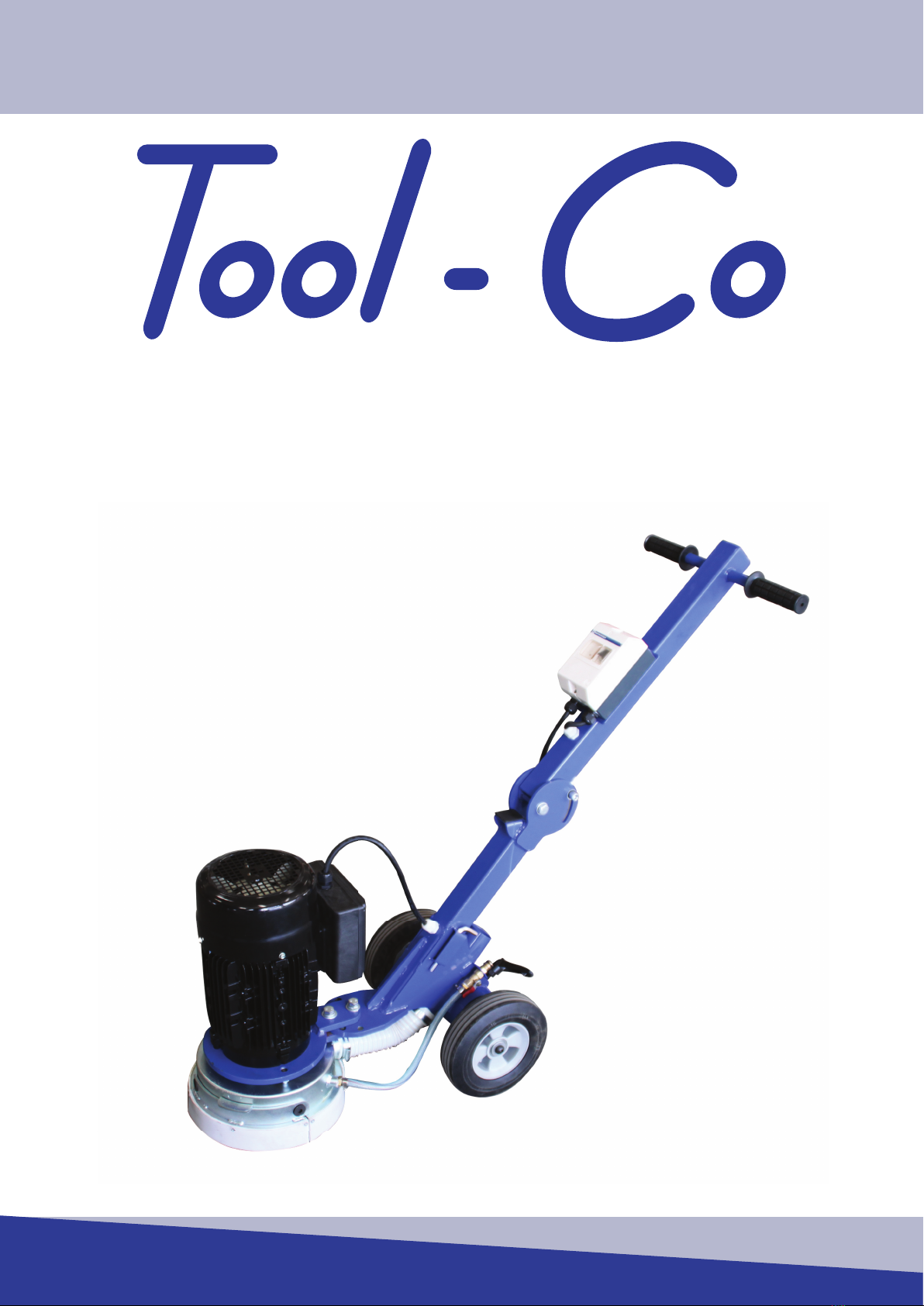
The oor grinder is a sturdy, reliable and easy to use machine.
The oor grinder is tted with a 2.2kW single phase motor. This motor oers
a direct drive to the grinding plate with the incorporation of a exible coupling
between the motor and the plate.
The shroud system is unique in design, automatically adjusting to suit segment
height and oor angle. This shroud system, when used in conjunction with an
appropriate industrial vacuum unit, eliminates dust loss during grinding. The
shroud has two removable sections to enable the operator to grind close up to
the wall etc. Please note that dust loss is possible when this section is removed.
The oor grinder comes complete with a water connection for wet grinding
should this be required. This incorporates a ball valve allowing the operator to
regulate the water supply to obtain the best grinding results.
The oor grinder has a foldable handle which enables it to be easily transported
in the trunk of most small vehicles. The rear wheels can also be extended
outward should the operator want more stability from the grinder. This requires
the use of an 8mm Allan Key. The operator can also raise or lower the height
of the handle to maximize their comfort when using the grinder, and the new
designed lifter system makes operator handy to use.
Pg.1

BDG250
TECHNICAL DATA
Motor Horsepower 3hp
Motor kW Rating 2.2kW
Motor Rotations Per Minute 1410rpm
Unit Weight 67kg
Plate Type Standard 250mm Plate
Plate Bolt Types M10 x 25 Countersunk Cap Screw
Main Construction Powder Coated Steel
Pg.2
SAFETY PRECAUTIONS
The oor grinder has been designed to minimize noise and vibration levels and
to provide maximum operator safety. However, incorrect use of the grinder may
cause serious injury and therefore the following precautions must be taken:
1. Do not use the grinder for longer than prescribed in your local environmental
working regulations, as the noise load from extensive daily use may result in
hearing defects.
2. Always use protective earplugs or earmus, goggles, gloves and correct
footwear.
3. Do not modify the grinder in any manner, or use a machine that has been
modied by anyone other than the manufacturer or authorised dealer.
4. Do not add weight to the machine to make the grinder work harder.
5. Reduce the number of segments on the grinding plate to increase performance.
6. Be sure that re-tipped and new grinding plates are properly balanced.
7. Do not run the grinder with grinding head raised any higher than necessary, i.e
tipped back on handle.
8. Always be sure that folding handle latch is secure and has not vibrated loose
after use.
9. When grinding, the machine is exposed to high vibration. Occasionally check
machine for bolts/nuts which may have vibrated loose.
10. Do not allow water or cotton to enter the interior of the motor.
MANUAL
OPERATION
The oor grinder is designed to be used either wet or dry. If the oor is being
ground dry, ensure a suitable industrial vacuum is connected and that the
operator is wearing suitable breathing respiratory equipment. Contact your
local work place health authority to ensure that their requirements regarding
respiratory equipment are being met.
STARTING THE GRINDER
1. Check the grinding plate being used is suitable for the material being ground
AND THAT THEY ARE CORRECTLY BALANCED.
2. Check that the grinding plates being used are in good order and properly
attached, with all countersunk bolts rmly in place. Check this occasionally
during use, as they can work loose during operation.
3. Check that the grinding plate is adjusted so that it sits level on the ground.
4. Check that all nuts and bolts on the folding handle latch are tight and rm.
5. Raise the grinding plates from the oor.
6. Start the motor by pressing the black switch on the starter box.
7. Lower the grinding plate and commence grinding.
STOPPING THE GRINDER
1. De-press the red stop button on the starter box.
NOTE:
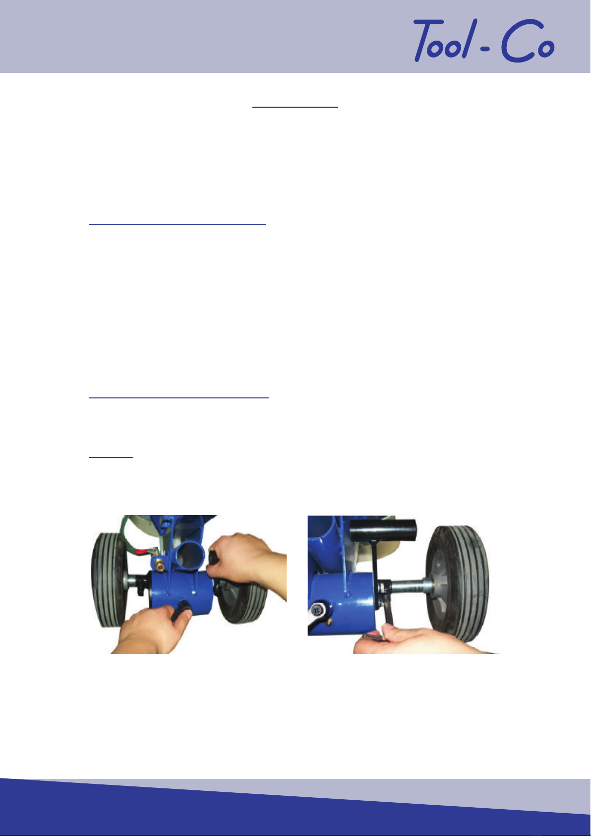
1. By turning and pushing the handles, you can x the vertical grinding position.
2. Adjust the axle’s width to improve grinding stability.
1 2
Pg.3

BDG250
MAINTENANCE
Daily cleaning: The motor in use should always be kept clean. No water, or debris
should be allowed to get into the interior of the motor.
Check on load current: While the motor is in operation, constant care should be taken
to keep the load current below the maximum recommended motor current rating.
Operational sounds: During operation of the motor there must be no rubbing sounds,
shrieks or other random noises. Stop the motor immediately and restart after
inspection and corrections have been made.
Check folding handle latch periodically. This is adjustable. To adjust, loosen the lock
nut on the latch and then screw in until a satisfactory tension has been
achieved.
The wheel bearings use sealed bearings and require no regular greasing.
*NB To minimize vibration and uneven blade wear, rotate plate every 2 hours.
Failure to do so can lead to premature wear of the exible coupling.*
**Ensure all re-tipped and new grinding plates are properly balanced.**
FAULT DIAGNOSIS
Symptom Possible Cause Action
Machine will not start
No power is available. Check that the power cable
is plugged in / switched on.
Machine is trying to start on
glue or sticky substance.
Clear a patch with scraper
and grind into the glue a
little, preventing build up.
Extension cord is too thin
or is too long.
Upgrade the extension
cord to a larger cable.
Grinder runs for 5-15
minutes, then stops.
The current allow screw is
not adjusted properly.
Adjust the current screw to
the right position.
Extension cable too long
and/or not made from
heavy enough cable.
Get electrician to check
extension lead
compatibility.
Grinder runs but does not
perform adequately. Motor defective. Repair or replace.
Grinder vibrates during use. Grinding plates not
correctly balanced.
Replace or re-balance
grinding plates.
Grinding noise coming from
grinding head when up on
jockey wheel.
Excessively worn motor
bearings. Have motor serviced.
Pg.4

MANUAL
Pg.5
PARTS DIAGRAM & LIST
Position
Number Part Number Description Qty
Req
1 BDG2501/0206 M5 x 20 Self Drill Screw 9
2 BDG2501/0207 Shroud Strip - Short 1
3 BDG2501/0208 Detachable Shroud 1
4 BDG2501/0209 Hexagon Countersunk Cap
Screw, M12 x 25 2
5 BDG2501/0210 M12 Hexagon Nuts 2
6 BDG2501/0211 Location Case 1
7 BDG2501/0212 Hexagon Head Bolt 4
BDG2501/0213 Hexagon Lock Nut 4
8 BDG2501/0214 Front Handle Assembly 1
9 BDG2501/0215 Base 1
10 BDG2501/0216 Electrical Motor 1
11 BDG2501/0217 Rubber Handle Grip 2
12 BDG2501/0218 Plain Washer 6
*NB “Qty Req” Indicates the quantity of parts required to make up a full set.*
**Parts are ordered individually.**

BDG250
Position
Number Part Number Description Qty
Req
13 BDG2501/0219 Hexagon Head Bolt 2
BDG2501/0220 Spring Lock Washer 2
14 BDG2501/0221 Handlebar Upper Arm 1
15 BDG2501/0222 Flexible Conduit L=450mm 1
16 BDG2501/0223-5 Complete Switch 1
BDG2501/0223 Breaker,Gv2-Me16c (Switch) 1
BDG2501/0224 Breaker Crust,Gv2-Mc02
(Switch Box) 1
BDG2501/0225 UVT Assemble
(Under Voltage Relay) 1
17 SP-LEAD Three Core Power Lead 1
G-AF001 Three Pin Plug Top 1
18
19
20
21
22
24
BDG2501/0228 Complete Locking Catch 1
23 BDG2501/0232 Plain Washer 4
BDG2501/0233 Spring Lock Washer 4
BDG2501/0234 Cross Recessed Pan Head
Screw 4
25 BDG2501/0236 Cable Splice, M18 2
26 BDG2501/0237 Plain Washer 2
27 BDG2501/0238 Cable Splice, M20 2
28 BDG2501/0464 Hexagon Jam Nut 1
29 BDG2501/0240 Rubber Pad 1
30 BDG2501/0241 Hexagon Head Bolt 1
31 BDG2501/0242 Handlebar Lower Arm 1
32 BDG2501/0243 Location Pin 1
33 BDG2501/0244 Hexagon Cap Screw 2
BDG2501/0160 Plain Washer 2
34 BDG2501/0436 Allen Key 6mm 1
BDG2501/0467 Allen Key 8mm 1
35
36
37
BDG2501/0437 Complete Water Feed
(With Lever) 1
38 BDG2501/0441 Adjustable Handle M12 x 25 1
39 BDG2501/0305 Wheel 2
40 BDG2501/0338 Hexagon Head Screw 2
Pg.6

MANUAL
Pg.7
Position
Number Part Number Description Qty
Req
41 BDG2501/0442 Spring Lock Washer 7
42 BDG2501/0443 Adjusting Shaft 2
43 BDG2501/0444 Wheel Shaft 2
44 BDG2501/0109 Grease Nipple (Zerk Fitting) 1
BDG2501/0445 Plain Washer 1
45 BDG2501/0446 Inner Hexagon Screw 2
46 BDG2501/0447 Eccentric Shaft 1
47 BDG2501/0448 Lift Lever 1
48 BDG2501/0266 Spacer Plate 1
49 BDG2501/0449 Spring Lock Washer 6
50 BDG2501/0450 Hexagon Bolt 2
51 BDG2501/0451 Pipe Clip 2
52 BDG2501/0452 Flexible Conduit Length 480mm 1
BDG2501/0453 Small Clip 2
53 BDG2501/0454 Vent-Pipe 1
54 BDG2501/0455 Big Plain Washer 3
55 BDG2501/0456 Water Spout 1
56 BDG2501/0457 Hexagon Head Bolt 4
BDG2501/0458 Plain Washer 4
57 BDG2501/0459 Shroud Strip Long 1
58 BDG2501/0460 Enclosure 1
59 BDG2501/0465 Key 1
60 BDG2501/0272 Flex Coupling 1
61 BDG2501/0461 Hexagon Head Bolt 2
62 BDG2501/0463 Hexagon Head Bolt 1
63 BDG2501/0466 Hexagon Nut 2
64 BDG2501/0267 Driving Sleeve 1
65 BDG2501/0462 Hexagon Head Bolt 2
66 BDG2501/0463 250mm Blank Plate 1
67 BDG2501/0277 Countersunk Cap Screw 2
68 BDG2501/0239 Dowel Disc 1
69 BDG2501/0290 M10 x 25
Countersunk Cap Screw 4
*NB “Qty Req” Indicates the quantity of parts required to make up a full set.*
**Parts are ordered individually.**

BDG250
RECOMMENDED VACUUM
Pg.8
VCM-AZ00280 Tool-Co G12-S
Power 1700W
Max Air Flow 300m3/h
Max Vacuum 220mbar
Primary Filter 1400 cm2, F8
Second Filter 1250 cm2, H13
Packaging Dimensions 65 x 42 x 110cm
Weight 44kg (40kg)
VCC-BM00431 Drum Pre-Filter
VCC-BM00287 Rear Filter
Designed to t the BDG250 Floor Grinder.
Uses a single motor with a two-stage ltering system.
Compatible with the continuous drop-down bagging system
for ease of use and e ciency. *Sold Separately*
VCC-BD00438
VCC-BM00241
VCC-BM00000
VCC-BD00225
VCC-BC00033
VCC-BC00034
VCC-BD00030
VCC-BM00004
VCC-BM00000 G12-S Vacuum Adaptor To Fit
BDG250 Floor Grinder
VCC-BM00241 Continuous Drop-Down Bag
VCC-BM00225 Drop-Down Bag Holder
VCC-BD00438 D50mm x 375mm Hose & Fitting
VCC-BC00033 D40mm Lower Wand
VCC-BC00034 D40mm Upper Wand
VCC-BD00030 Floor Brush 40mm x 400mm
VCC-BM00004 Spare Brush
MANUAL
RECOMMENDED TOOLS
Pg.9
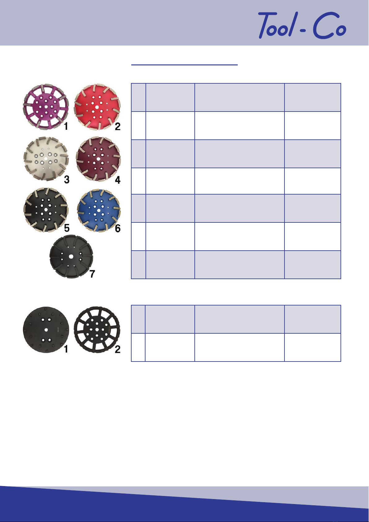
1LFG250S0 250mm x 12mm x 16 Seg
Purple 16#
Medium Floor
Coating
Removal
2LFG250S 250mm x 12mm x 20 Seg
Red 25#
Medium Floor
Coarse
Grinding
3LFG250S5 250mm x 12mm x 20 Seg
Silver 40#
Medium Floor
Medium
Grinding
4LFG250S2 250mm x 12mm x 20 Seg
Brown 80#
Medium Floor
Fine Grinding
5LFG250S3 250mm x 12mm x 20 Seg
Black 120#
Medium Floor
Extra Fine
Grinding
6LFG250SA 250mm x 12mm x 20 Seg
Blue 25#
Abrasive Floor
Coarse
Grinding
7BFG250P 250mm x 10mm x 20 Seg
Black 25#
Hard Floor
Coarse
Grinding
1LCFE16PCD 250mm x 16PCD
Premium
Aggressive
Coating
Removal
2LCFE15PCD 250mm x 15PCD
Economy
Aggressive
Coating
Removal

DISTRIBUTOR
Manual Ver.1-2020
Table of contents
Popular Floor Machine manuals by other brands

HAKO
HAKO Scrubmaster B310 R CL/TB 1020 instruction manual

Mytee
Mytee 1003DX Speedster Instruction manual & safety guide

Tornado
Tornado GLAZER P 1600 Operation & maintenance manual

MULTIQUIP
MULTIQUIP RX 1510-C Operation manual

HAKO
HAKO Hakomatic B115R operating manual

Mi-T-M
Mi-T-M AW-7020-8004 quick start guide


Tennant
Tennant 800 Service manual

Nilfisk-Advance
Nilfisk-Advance SW900 Use and maintenance

Nilfisk-Advance
Nilfisk-Advance BR 1100C Instructions for use

U.S. Products
U.S. Products KING COBRA 310 Information & operating instructions

Nobles
Nobles Marksmant 412 Specifications

Edco
Edco DDG-9-I-0315 Operator's instruction manual