Tool-Co BCA350 User manual

OPERATING MANUAL
BCA350
MASONRY SAW


MANUAL
CONTENT
Safety Precautions : Page 1
General Safety Rules : Page 2
Health Warnings : Page 2
Unpack & Inspection : Page 3
Technical Data : Page 3
Assembly & Operation : Page 4
Working Instructions : Page 5
Fault Diagnosis : Pages 6 - 7
Maintenance : Page 8
Exploded Diagram A : Page 9
Diagram A Parts List : Page 10 - 12
Exploded Diagram B : Page 13
Diagram B Parts List : Page 14
Recommended Blades : Page 15 - 16

BCA350
SAFETY PRECAUTIONS
The saw blade should be inspected daily for excessive wear, core cracks, and
arbor damage. Replace the blade if it shows any signs of damage.
• To mount the blade; clean the arbor and outer fl ange, then tighten the nut
to secure the blade.
• Keep limbs and fi ngers clear from the blade when it is in use.
• To reduce risk of electrical shock, it is recommended to use a Ground Fault
Circuit Interrupter (GFCI) switch
• Always have a qualifi ed technician service the machine.
We recommend that you use the following Personal Protective Equipment
(PPE) when operating the machine:
WEAR HEARING PROTECTION
WEAR EYE PROTECTION
WEAR A DUST MASK
USE A BLADE GUARD WHEN OPERATING THE SAW
Pg.1

MANUAL
Pg.2
GENERAL SAFETY RULES
• Never misuse the machine or work in an unsafe manner.
• Always wear the correct PPE when operating the machine. (See Page1)
• Always remain alert when the machine is in use. Operating the machine
while distracted may lead to serious injury.
• Before you start working, do a basic risk assessment of your environment.
• Take measures to ensure that the machine is in a safe and trouble-free
condition prior to usage. Use the machine only when all protective devices
(i.e. guards, noise absorbers, emergency shut-off devices) are located and
operating as intended.
• A visual check of the machine must be made at least once a shift to ensure
that visible damages or faults are recognized. Any changes (including
changes in the performance or behavior of the machine) must be reported
to the supervisor. If required, cut off the power and correct any faults
before using the machine.
• In the case of a malfunction, stop the machine immediately, then follow
the operating instruction steps and look for any damages or faults.
• Be sure to connect the plug to a properly grounded socket, and that there
is no damage to the cable to reduce the risk of electric shock.
HEALTH WARNINGS
Dust is created when sawing, which could contain harmful particles.
Some examples of these particles include:
• Lead from lead based paints,
• Crystalline silica from bricks, concrete, and other masonry products.
• Arsenic and chromium from chemically-treated lumber.
Your risk to these types of exposure varies depending on how often you do
this type of work and your environment.
To reduce your exposure to these chemicals: work in a well ventilated area,
and work with approved safety equipment, such as dust masks that are
specially designed to fi lter out microscopic particles.

BCA350
TECHNICAL DATA
Rated Voltage 230V/50Hz
Rated Power 2.2kW
Cutting Materials Block/Brick
Max Cutting Depth & Angles 90mm (90°) & 50mm (45°)
Cutting Length 650mm
Rated Speed 2800rpm
Blade Diameter 350mm
Arbor Size 25.4mm
Weight 72kg
Dimensions L x W x H 1276 x 736 x 862mm
Pg.3
UNPACK & INSPECTION
After opening the container, carefully lift the saw frame handles and place it on
a fl at, level working area. Be certain that you have the following items before
you discard the container:
• Saw: 1 piece
• Saw frame support: 4 pieces
• Water pump: 1 piece
• Hex Wrench No. 4,6,8: 1 piece/each
• Adjustable Wrench: 1 piece
• Wrench: 1 piece
The Masonry Saw is shipped completely assembled and ready for use
excluding the diamond blade. Inspect the saw for shipping damage. If any
damage is found, contact the shipper immediately and fi le a freight claim.

MANUAL
Pg.4
ASSEMBLY & OPERATION
• After opening the package and confi rming everything has been included,
install the 4 removable legs underneath masonry saw frame by tightening
knobs.
• Plug the rubber block into the drain hole. Please inspect the motor and
wires before powering up the saw.
• DO NOT connect the plug into the power socket before installing blade.
• Keep the blade shaft clean and dry, remove the blade safety guard, install
the blade on the blade shaft, tighten the collar.
• Fill the water pan with clean water and fully submerge the water pump.
• Connect power to the pump and be sure there is enough water fl ow to the
blade before cutting.
• Keep the input hole of water pump clear, check regularly to avoid slurry
block.
• Rotate the blade manually (slowly) to check the blade condition, make
sure it’s rolling smoothly and is properly mounted.
• Always ensure you are using the correct rated voltage.
• Keep the motor rotating in no-load condition for one minute before cutting
in order to check related parts. Listen to the sound of the machine in
operation for abnormal behavior.
• DO NOT use if there is anything wrong or unusual.
• Check pump operation to ensure enough water is fl owing during operation.
• Put the cutting head in the desired position: either for sawing at right
angles or for mitering (90° or 45°). Loosen the bolt slightly by using the
ring wrench then tilt the head into the desired position. Tighten the bolt.
The exact position 90° or 45° can be adjusted by means of the adjustment
bolts.
• When nearing completion of the cut, pull back the cut, and slightly hold
back the conveyor cart. Always keep the blade out of the cutting slot
before turning off the motor.
• Place the cutting material on the conveyor cart, clamp and hold it fi rmly
against the backstop. Align the cutting material line with the blade cut line.
• The motor will stop in an overload condition. This means the overheat
protection device is working as intended.
• Turn off power and unplug the machine after each use. Empty the water
tank, remove dust, debris and slurry from machine. Keep the equipment
clean and dry.

BCA350
Pg.5
WORKING INSTRUCTIONS
• Please study this operating manual carefully and ensure you follow the
safety guidelines before using the BCA350 Masonry Saw.
• Professional training for workers is necessary.
• Always check work area for hidden wires, water or gas pipes before
working.
• Sawing action requires the use of water, since the use of electrical
equipment in wet areas is hazardous, the equipment must be grounded.
Always wear insulated footwear and gloves for extra protection against
shock hazards.
• Always wear safety goggles or glasses with side shields.
• Avoid vibrating or bumping the saw during cutting to insure equipment and
blade lifespan is not reduced.
• Keep any electrical equipment, the motor and cables away from water.
• Keep the blade free from any material when you start the saw.
• DO NOT operate without water. Suffi cient water fl ow is required to cool
blade and remove slurry.
• DO NOT remove the safety guard while the machine is in operation.
• DO NOT use the machine when you are tired, distracted or under the
infl uence of drugs, alcohol and any medication causing decreased
awareness or control.

MANUAL
FAULT DIAGNOSIS
Symptom Possible Cause Action
Machine does not run when
switched on
Power cord not properly
fi xed/plugged in
Check that the machine is
properly connected to the
power supply
Power Cord Defective
Have the power cord
checked or replace if
necessary
Main power switch
defective
Have the main power
switched checked and
replace if necessary by a
qualifi ed electrician
Loose electrical connection
inside the electric system
Have the whole electric
system of the machine
checked by a qualifi ed
electrician
Motor defective
Have the motor checked
and replace if necessary by
a qualifi ed technician
Insuffi cient water fl ow
The water pump or water
pipe is blocked
Check and clean water
pump and water pipe
The water pump or water
pipe is faulty or damaged
Check the water pump
and pipe and replace if
necessary by a qualifi ed
technician
Motor stops (power cut out)
Too much pressure exerted
while cutting
Exert less pressure when
cutting
Incorrect specifi cation for
saw blade
Use a saw blade which
corresponds to the material
being cut
Saw has a defective
electrical system
Have the electrical system
checking by a qualifi ed
electrician
Poor machine performance
(low power)
Power cord or extension
cable is too long or the
cable is still wound up
inside the cable drum
Use a power cord or
extension cable of the
rated length, use a cable
drum with cable fully
extended
Power network is
insuffi cient
Observe the electrical
ratings of the machine and
connect it only to a power
network which is rating
compliant
Drive motor no longer runs
at rated RPM
Have the motor checked
and replaced by a qualifi ed
technician if necessary
Pg.6

BCA350
Symptom Possible Cause Action
Irregular run of the saw
blade
Poor tension in the blade
material
Return the saw blade to the
manufacturer
Saw blade wobbles when
the saw is running
Saw blade is damaged or
bent
Have the saw blade
aligned or fl attened
Clean the receiving fl ange
Flange of the saw blade is
damaged
Replace the saw blade
fl ange
Shaft of the motor is bent Replace the electric motor
Diamond segment becomes
loose
Overheating of the saw
blade
Have the diamond segment
soldered on the blade
again
Coolant is not suffi cient Ensure optimum fl ow of
cooling water
Excessive wear
Wrong type of saw blade Use a harder blade bond
Shaft of motor causes
wobbling
Have bearings of the motor
replaced, or replace the
motor
Overheating Ensure optimum fl ow of
cooling water
Cracks in or near the
diamond segment
Saw blade bond too hard Use a softer blade bond
Fixed fl ange is worn out Have the fi xed fl ange
replaced
Motor shaft bearing is worn Replace the bearing of the
motor shaft
The center hole in the saw
blade has become wider
due to wear
The saw blade has slipped
on the motor shaft when
running
The arbor of the saw blade
must be fi tted with an
adapter ring
Check the receiving fl ange
and have it replaced if
necessary
Appearance of cut is not
optimal
Poor tension in the blade
material
Return the blade to the
manufacturer
Too much load placed on
the saw blade Use a suitable blade
Diamond segments are
blunt
Sharpen the diamond
blade on an abrasive
material
Grinding marks on the saw
blade
Material is not being fed
parallel to the saw blade
Ensure that the direction of
feed is parallel to the blade
Poor tension in the blade
material
Adjust the roller table or
have it adjusted
Too much load on the
blade
Exert less pressure when
cutting, proceed slower
Pg.7

MANUAL
MAINTENANCE
After every use of the machine:
• Remove dirty water from the machine.
• Remove dirt and mud from the bottom of the machine.
• Check and renew worn parts to keep the parts in good condition, and
check belts for wear and proper tension.
• Check and tighten screw nuts and wire connections to Keep them in good
condition.
Before using the machine again:
• Connect the machine to an electrical power outlet equipped with a Ground
Fault Circuit Interrupter (GFCI) switch. If the safety power breaker cuts off
the electrical power supply, DO NOT try to operate the machine before
having it checked by an authorized technician fi rst.
Before storing the machine for a prolonged period of time:
• Clean and lubricate all moving parts.
After not using the machine for a long period, or removing from storage:
• Check that the legs are safely fi xed.
• Check that all screw joints and nuts are fi xed.
• Check that the roller table is in it’s guides and that it moves easily.
• With the saw blade removed, switch on the motor for a moment and switch
it back off again. If the motor does not run, have the machine inspected by
a qualifi ed technician.
WARNING!
For your safety, before performing any maintenance on the
machine, ensure that the power is turned off and unplugged.
Pg.8
BCA350
Pg.9
Pg.10
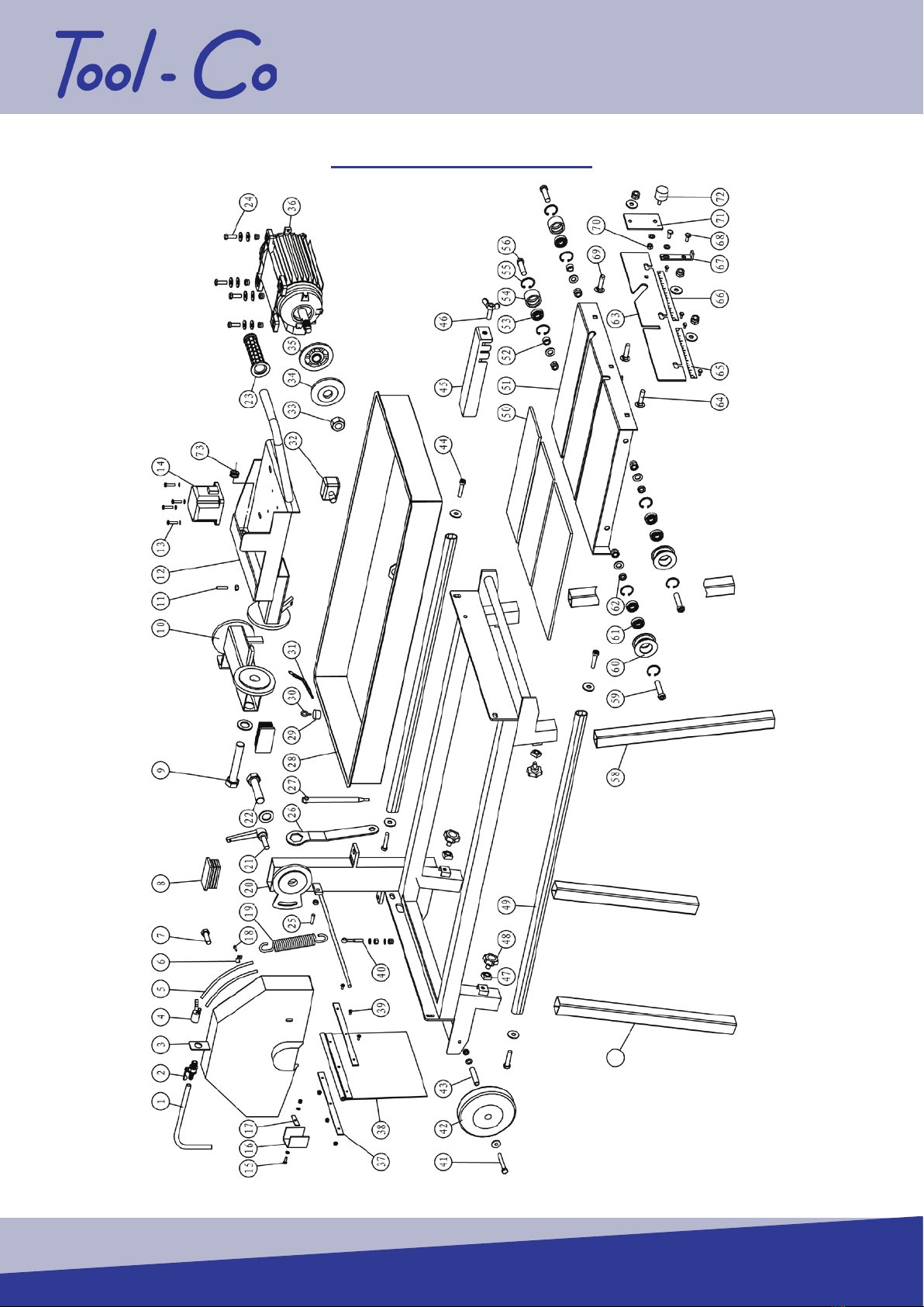
EXPLODED DIAGRAM A

MANUAL
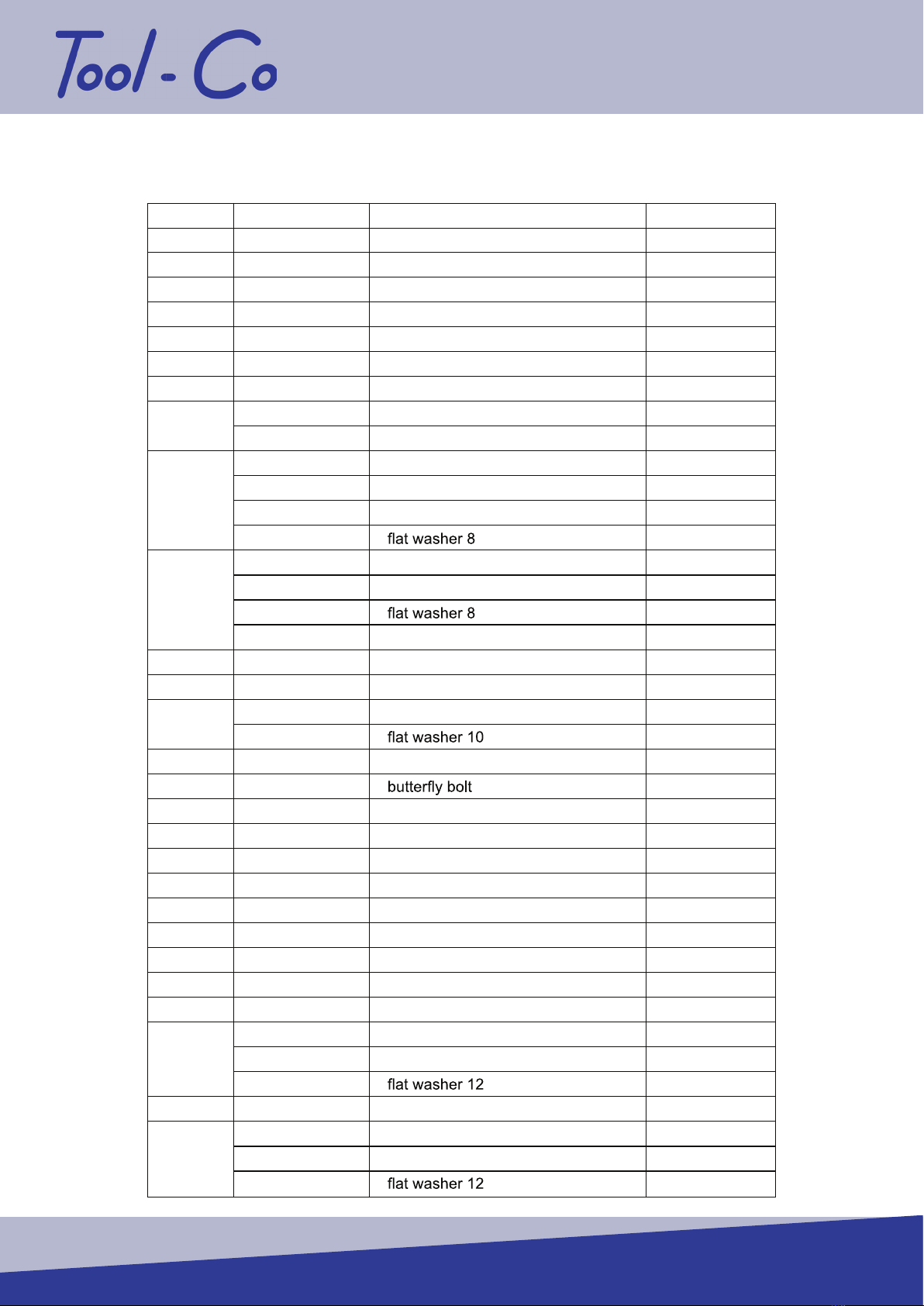
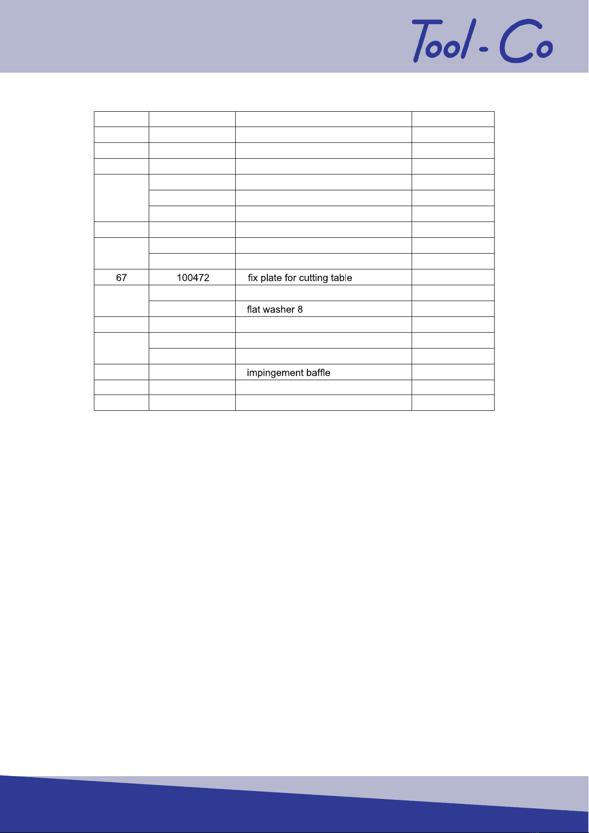
Item No. Part No. Description Qty
1 100222 water tube12×2-2200
2 100399 water valve
3 100400 blade cover
4 100384 tee joint
5 100401 water tube5×1.5(300mm)
6 100402 clamp
7 100403 bolt M8X16
8 100404 plastic part
100405 hex.head bolt M20X120
100406
10 100407 rocker arm assembly
100408 Hex.socket set screws M8X30
100409 hex nut M8
12 100410 bracket for motor
100411 Cross Recess Head Screw M5X45
100412
14 100413 switch
100414 hex. Head bolt M6X20
100415
100416 hex. Lock nut M6
16 100417 water curtain
17 100418 water curtain clamp
18 100419 Hex. head tapping screws
19 100420 spring
20 100421 lathe bed
21 100422 handle
100423 hex.head bolt M20X80
100406
23 100217 jacket for handle
100424 hex.head bolt M8X30
100425 washer 8
100213 hex. Lock nut M8
100408 Hex.socket set screws M8X30
100409 hex nut M8
26 100426 wrench
27 100427 pole for assemble and unassemble
28 100428 water tank
29 100429 rubber stopper
30 100430 screw eye
9
11
13
15
22
24
25
1
1
1
1
2
2
1
2
1
1
1
2
2
1
4
4
1
1
2
1
1
1
2
1
1
1
1
1
1
4
8
4
1
1
1
1
1
1
1
DIAGRAM A PARTS LIST
Pg.10
BCA350
31 100431 ring
32 100432 water pump
33 100433 hex nut M20
34 100434 outside platen
35 100435 inside platen
36 100436 motor
37 100437 dead plate for water curtain clamp
38 100438 water curtain 400X300
100439 Cross Recess Head Screw M4X10
100440 hex nut M4
100441 eyelet bolt M8X50
100305 hex nut M8
100338 hex. Lock nut M8
100442
100443 hex.head bolt M8X65
100444 big washer 8
100109
100445 hex. Lock nut M8
42 100446 wheel
43 100447 axle
100448 socket head screw
100266
45 100449 guide plate
46 100450
47 100451 square nut M10
48 100452 handle for tighten legs
49 100453 guide rail
50 100454 rubber plate
51 100455 cutting table
52 100456 cover for right roller
53 100457 bearing 6201RS
54 100458 right roller
55 100459 retaining ring 32
100460 socket head screw M12X45
100239 hex. Lock nut M12
100218
58 100462 support legs
100463 socket head screw M12X50
100239 hex. Lock nut M12
100218
39
40
41
44
56
59
1
1
1
1
1
1
2
1
3
3
1
1
1
2
2
4
4
4
2
2
4
4
1
1
4
4
2
1
1
2
2
2
8
2
2
2
2
2
2
2
Pg.11
MANUAL
60 100464 left roller
61 100457 bearing 6201RS
62 100465 cover for left roller
63 100466 back stop
100467 round head square neck bolt M10X30
100468 hex.Look nut M10
100469 big washer 10
65 100470 ruler 1
100471 ruler 2
100599 tack rivet 2.5X5
100473 hex.head bolt M8X25
100442
69 100474 half-round head square neck bolt M10X35
100475 hex. Nut M6
100476 spring washer
71 100477
72 100478 rubber hat
73 100551 Cord Sleeve
64
66
68
2
4
2
1
3
3
3
1
1
4
1
2
2
1
1
1
1
1
1
70
Pg.12
BCA350
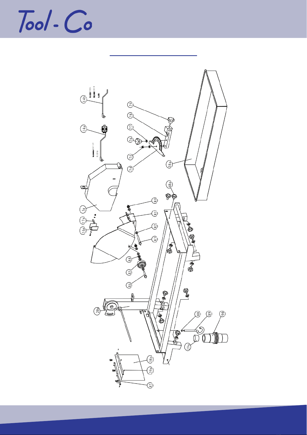
EXPLODED DIAGRAM B
Pg.13

MANUAL
Item No. Part No. Description Qty
3a 100552 blade cover
14a 100553 switch & Swiss plugs
100553 switch
100433-1 plug for South Africa
100554 right angle spring
16a 100555 water curtain
17a 100556 plate
20a 100557 lathe bed
28a 100558 water tank
29a 100559 rubber plug
38a 100454 water curtain
100560 Cross Recess Head Screw M4X10
100440 hex nut M4
100443 hex screw M8
100444 washer 8
100109
100445 hex lock nut M8
42a 100446 wheel
43a 100447 axle
73 100551 sleeve3X1.5
74 100561 angle gage
75 100713 hex nut
76 100562 stellate knob II
77 100442
78 100563 back stop
79 100296 stellate knob I
80 100629 hex lock screw
81 100564 blade cover
82 100109
83 100565 hex screw
84 100662 hex nut
85 100714 nylon wheel
86 100566 hex screw
87 100567 ring
88 100568 hex nut
89 100569 hock
90 100570 water-proof joint
29a
1
1
1
1
3
1
1
1
1
1
1
3
3
2
2
4
2
2
2
1
1
1
1
1
1
1
2
1
7
1
1
1
1
3
1
1
1
41a
14b
DIAGRAM B PARTS LIST
Pg.14

BCA350
1BM300MS 300 x 3.2 x 10 x 25.4mm Masonry Blade
2BM350MS 350 x 3.2 x 10 x 25.4mm Masonry Blade
1LVR300P 300 x 3.1 x 25.4mm Rescue Blade
2LVR350P 350 x 3.1 x 25.4mm Rescue Blade
1HO350TP 350 x 3.2 x 12 x 25.4mm Trade Pro
1LSDC300 300 x 2.4 x 7 x 25.4mm Hard Materials
2LSDC350 350 x 3.2 x 5 x 25.4mm Hard Materials
3LSDC450 450 x 4 x 7 x 25.4mm Hard Materials
RECOMMENDED BLADES
1BO300DA 300 x 3 x 12 x 25.4mm Economy
2BO350DA 350 x 3.2 x 15 x 25.4mm Economy
Pg.15

MANUAL
RECOMMENDED BLADES
1BO300CS 300 x 3 x 12 x 25.4mm Standard Blade
2BO350CS 350 x 3.2 x 15 x 25.4mm Standard Blade
1BO350CH 350 x 3 x 15 x 25mm Premium Blade
Pg.16

BCA350
Pg.17
Table of contents
Popular Saw manuals by other brands

Parkside
Parkside PHKSU 710 A1 translation of original operation manual

Pattfield Ergo Tools
Pattfield Ergo Tools PE-600 MHKS-2 Original instructions

Makita
Makita 5603R instruction manual

Grizzly
Grizzly G1012 parts list

Bosch
Bosch GSA 1200 E Professional Original instructions

Milwaukee
Milwaukee M18 FCS66 user manual


