Toolex Platinum Series User manual

OIL FREE
AIR COMPRESSOR
INSTRUCTION MANUAL
Platinum Series
1.

IMPORTANT SAFETY INSTRUCTIONS AND GUIDELINES
Save all instructions
Improper operation or maintenance of this product could result
in serious injury and/or property damage. Read and understand all of the warnings and safety
instructions provided before using this equipment.
The air compressor should be operated on a dedicated 10-amp circuit.
If the circuit does not have 10 free amps available, a larger circuit must
be used. Always use more air hose before utilizing extension cords. Low
voltage could cause damage to the motor.
Risk of Moving Parts If the air compressor is in operation, all guards and covers should be
attached or installed correctly. If any guard or cover has been damaged,
do not operate the equipment until the proper personnel have correctly
repaired the equipment. The power cord should be free of any moving
parts, twisting and/or crimping while in use and while in storage.
Risk of Burns There are surfaces on your air compressor that while in operation and
there¬after can cause serious burns if touched. The equipment should be
allowed time to cool before any maintenance is attempted. Items such as
the com¬pressor pump and the outlet tube are normally hot during and
after operation.
Risk of Falling Operation of the air compressor should always be in a position that is
stable. Never use the air compressor on a rooftop or elevated position
that could allow the unit to fall or be tipped over. Use additional air hose
for elevated jobs.
Risk from Flying
Objects
Always wear approved safety glasses with side shields when the air
compressor is in use. Turn off the air compressor and drain the air tank
before performing any type of maintenance or disassembly of the hoses
or ttings. Never point any nozzle or sprayer toward any part of the body
or at other people or animals.
Risk to Breathing Avoid using the air compressor in conned areas. Always have adequate
space (30 cm) on all sides of the air compressor. Also keep children,
pets, and others out of the area of operation. This air compressor does
not provide breathable air for anyone or any auxiliary breathing device.
Spraying material will always need to be in another area away from the
air compressor to not allow intake air to damage the air compressor lter.
Risk of Electrical shock Never utilize the air compressor in the rain or wet conditions. Any
electrical issues or repairs should be performed by authorized personnel
such as an electrician and should comply with all national and local
electrical codes. The air compressor should also have the proper three
prong grounding plug, correct voltage, and adequate fuse protection.
2.

Risk of Explosion or re Never operate the compressor near combustible materials, gasoline
or solvent vapors. If spraying ammable materials, locate the air
compressor at least 50m away from the spray area. Never operate the
air compressor indoors or in a conned area.
Risk of Bursting Always drain the air compressor tank daily or after each use. If the
tank develops a leak, then replace the air compressor. Never use
the air compressor after a leak has been found or try to make any
modications to the tank. Never modify the air compressor’s factory
settings which control the tank pressure or any other function.
PARTS & FEATURES
Drain Valve: Used to drain condensation from
the air tank. Located at bottom of tank. (52)
Motor Thermal Overload: The motor has an
automatic thermal overload protector. If the
motor overheats, this protector will shut off the
motor. The motor must be allowed 30 minutes to
cool before restarting.
Pressure Switch: This controls the power to
the motor and also the cut-in/cut-out pressure
settings. This switch serves as the Auto-On/Off
positions for the unit. (45)
Air Intake Filter: Provides clean air to the pump
and must always be kept free of debris. Check
on a daily basis or before each use. (38)
Check Valve: When the pump is not in
operation the valve closes to retain air pressure
inside the tank. (60)
Pressure Relief Valve: The pressure relief
valve located on the side of the pressure switch
is designed to automatically release compressed
air when the air compressor reaches cut-out
pressure. The release air should only escape
momentarily and the valve should then close.
Tank Safety Valve: Used to allow excess tank
pressure to escape into the atmosphere. This
valve should only open when the tank pressure
is above the maximum rated pressure. (46)
Outlet Pressure Gauge: Indicates the outgoing
air pressure to the tool and is controlled by the
regulator. (42)
Tank Pressure Gauge: Indicates the reserve air
pressure in the tank. (43)
Regulator: The regulator controls the air
pressure coming from the air tank. To increase
the pressure, turn the knob clockwise and
to decrease the pres¬sure turn the knob
counterclockwise. (41)
3.

PARTS DIAGRAM
1. Cover
2. Left Fan
3. Left Crankcase
4. Connecting Rod
5. Piston Cup
6. Binder Plate
7. Con Rod Bolt
8. Cylinder
9. Cylinder Seal
10. Head Seal
11. Cylinder Head
12. Head Bolt
13. ‘O’ Ring
14. Transfer Pipe
15. Valve Plate Bolt
16. Valve Block
17. Reed Valve
18. Reed Valve
19. Valve Plate
20. Washer
21. Right Fan
22. Shaft Seal
23. Bearing 6908-2z
24. Bearing Bolt
25. Bearing Bolt
26. Right Crankcase
27. Protection Ring
28. Assembly Bolt
29. Assembly Bolt
30. Spring Washer
31. Stator
32. Assembly Nut
33. Rotor
34. Bearing 6203-2z
35. Adjusting Washer
36. Rubber Mount
37. Spring Washer
38. Air Filter
39. Elbow
40. Deating Tap
41. Regulator
42. Outlet Pressure gauge
43. Tank Pressure gauge
44. Connector
45. Pressure Switch
46. Safety Valve
47. Handle
48. Tank
49. Wheel Nut
50. Wheel
51. Bolt (Axle)
52. Tank Drain Cock
53. Bolt
54. Washer
55. Cushion Foot
56. Washer
57. Nut
58. Pipe
59. Actuated Valve
60. Non Return Valve
61. Plug and Lead
62. Capacitor
63. Capacitor cover
4.

INSTALLATION & ASSEMBLY
The air compressor should be turned off and
unplugged from the power source before any
maintenance is performed as well as the air
bled from the tank and the unit allowed time to
cool. Personal injuries could occur from moving
parts, electrical sources, compressed air or hot
surfaces.
Location of the Air Compressor
The air compressor should always be located
in a clean, dry, and well-ventilated environment.
The unit should have at minimum, 30cm of
space on each side. The air lter intake should
be free of any debris or obstructions. Check the
air lter on a daily basis to be sure it is clean and
in working order.
Grounding Instructions
This product should be grounded. In the event
of an electrical short circuit, grounding reduces
the risk of electric shock by providing an escape
wire for the electric current. This prod¬uct is
equipped with a cord having a grounding wire
with an appropriate grounding plug. The plug
must be plugged into an outlet that is prop¬erly
installed and grounded in accordance with
all local codes and ordinances. Check with a
qualied electrician or service personnel if these
instructions are not completely under¬stood
or if in doubt as to whether the tool is properly
grounded.
Improper installation of the grounding plug will
result in a risk of electric shock. If repair or
replacement of the cord or plug is necessary,
do not connect the grounding wire to either
at blade terminal. The wire with insula¬tion
having an outer surface that is green with or
with¬out yellow stripes is the grounding wire.
Check with a qualied electrician or serviceman
if the grounding instructions are not completely
understood, or if in doubt as to whether the
product is properly grounded. Do not modify the
plug provided; if it will not t the outlet, have the
proper outlet installed by a qualied electrician.
This product is for use on a circuit having a
nominal rating of 230 volts and is factory-
equipped with a specic electric cord and plug
to permit connection to a proper electric circuit.
Make sure that the product is connected to an
outlet having the same conguration as the plug.
No adapter should be used with this product. If
the product must be reconnected for use on a
different type of electric circuit, qualied service
personnel should make the reconnection.
Extension Cords
Make sure your extension cord is in good
condition. When using an extension cord, be
sure to use one heavy enough to carry the
current your product will draw. An undersized
cord will cause a drop in line voltage resulting in
loss of power and overheating.
Break in Procedures
No break in procedure is required by the user.
This product is factory tested to ensure proper
operation and performance. Compressor must
always be turned ON or OFF using pressure
switch. Never turn machine OFF or ON using
power source
DRAIN
5.

Daily Start-Up Procedures
1. Set the Auto-On/Off lever to the off position.
2. Check the air compressor visually for any
damage or obstruction.
3. Close the drain valve.
4. Plug the power cord into the proper
receptacle.
5. Turn the Auto-on/Off lever to the On-Auto
position and the compressor will start and build
air pressure in the tank to cut-out pressure and
then shut off automatically.
6. Adjust the regulator to a PSI setting that
is needed for your application and be sure
it is within the safety standards required to
perform the task. If using a pneumatic tool, the
manufacturer should have recommendations in
the manual for the particular tool on operating
PSI settings.
7. The air compressor is now ready for use.
MAINTENANCE
NOTE: Qualied service personnel should
perform any service procedure not covered in
the maintenance schedule below.
ITEMS TO CHECK/CHANGE Before Each
Use or Daily
Check Tank Safety Valve X
Overall Unit Visual Check X
Check Air Filter (
(More frequently in dusty or humid
environments)
X
To ensure efcient operation and longer life of
the air compressor unit, a routine maintenance
schedule should be followed. The following
schedule is geared toward a consumer whose
compressor is used in a normal working
environment on a daily basis. If neces¬sary,
the schedule should be modied to suit the
con¬dition under which your compressor is
used. The modications will depend upon the
hours of operation and the working environment.
Air compressors used in an extremely dirty and/
or hostile environment will require a greater
frequency of all maintenance checks.
Daily Shut-Down Procedures
1. Set the Auto-On/Off lever to the Off position.
2. Unplug the power cord from the receptacle.
3. Set the outlet pressure to zero on the
regulator.
4. Remove any air tools or accessories.
5. Open the drain valve allowing air to bleed
from the tank. After all of the air has bled from
the tank, close the drain valve to prevent debris
buildup in the valve.
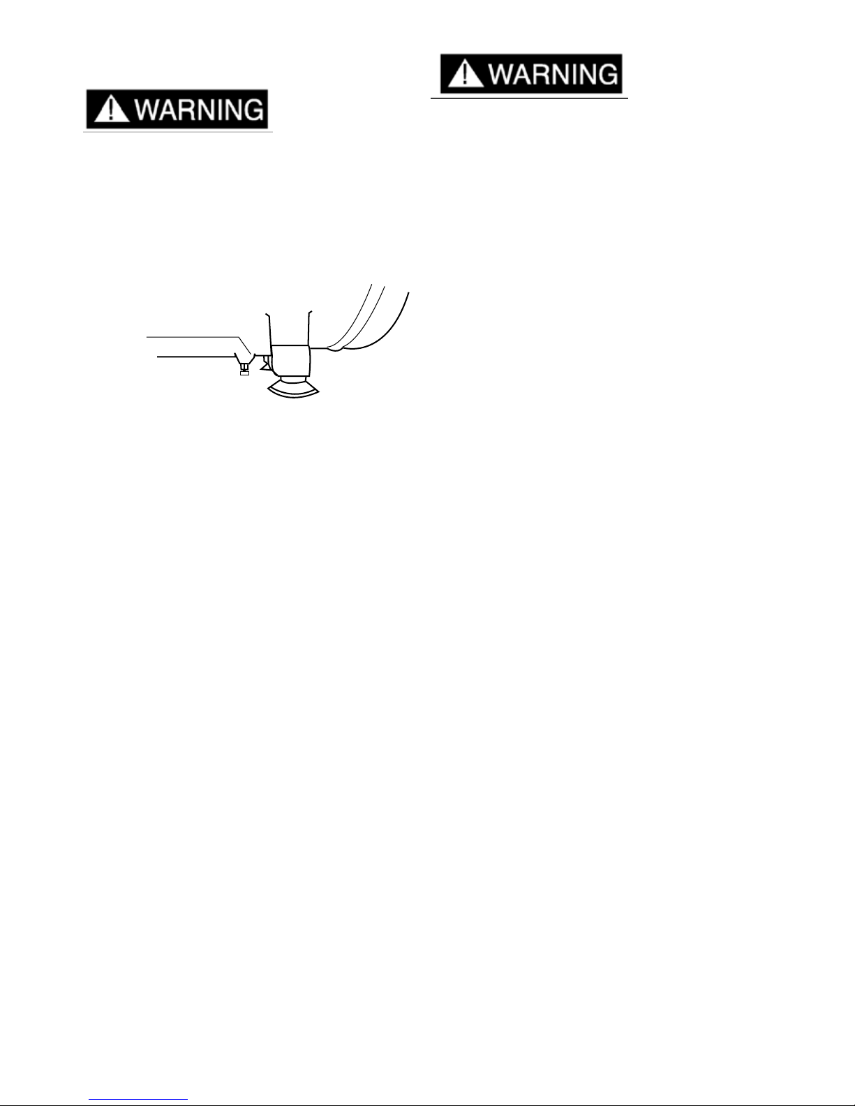
When draining the tank, always use ear and
eye protection. Drain the tank in a suitable
location; condensation will be present in most
cases of draining.
Water that remains in the tank during storage
will corrode and weaken the air tank, which
could cause the tank to rupture. To avoid serious
injury, be sure to drain the tank after each use or
daily.
The air compressor should be turned off and
unplugged from the power source before any
maintenance is performed as well as the air
bled from the tank and the unit allowed time to
cool. Personal injuries could occur from moving
parts, electrical sources, compressed air or hot
surfaces.
STORAGE
For storing the air compressor, be sure to do the
following:
1. Turn the unit off and unplug the power cord
from the receptacle.
2. Remove all air hoses, accessories, and air
tools from the air compressor.
3. Perform the daily maintenance schedule.
4. Open the drain valve to bleed all air from the
tank.
5. Close the drain valve.
6. Store the air compressor in a clean and dry
location.
OPERATION PROCEDURES
6.

TROUBLESHOOTING GUIDE
The air compressor should be turned off and unplugged from the power source before any
maintenance is performed as well as the air bled from the tank and the unit allowed time to
cool. Personal injuries could occur from moving parts, electrical sources, compressed air, or hot
surfaces.
Problem Possible Correction
Air leaks at the check valve or
at the pressure relief valve.
A defective check valve results in a constant air leak at the
pressure release valve when there is pressure in the tank and
the compressor is shut off. Drain the tank, then remove and
clean or replace the check valve.
Air leaks between head and
cylinder.
Be sure of proper torque on head bolts. If leak remains, contact
a service technician.
Air leak from safety valve Operate the safety valve manually by pulling on the ring. If the
valve continues to leak when in the closed position, it should be
replaced.
Pressure reading on the
regulated pressure gauge
drops when an accessory is
used.
If there is an excessive amount of pressure drop when the
accessory is used, replace the regulator.
NOTE:
Adjust the regulated pressure under ow conditions (while
accessory is being used). It is normal for the gauge to show
minimal pressure loss during initial use of the tool.
Excessive tank pressure. Move the Auto-On/Off lever to the Off position. If the unit
doesn’t shut off, unplug it from the power source and contact a
service technician.
Motor will not start. Make sure power cord is plugged in and the switch is on.
Inspect for the proper size fuse in your circuit box. If the fuse
was tripped reset it and restart the unit. If repeated tripping
occurs, replace the check valve or contact your service
technician.
Excessive moisture in the
discharge air.
Remove the water in the tank by draining after each use. High
humidity environments will cause excessive condensation.
Utilize water lters on your air line.
NOTE:
Water condensation is not caused by compressor malfunction.
Be sure the compressor’s air output is greater than your tool’s
air consumption rate.
Air leaks from the tank body or
tank welds.
Never drill into weld or otherwise modify the air tank or it will
weaken. The tank can rupture or explode. Compressor cannot
be repaired. Discontinue use of the air compressor.
7.
Table of contents
Other Toolex Air Compressor manuals