Toolex 597470 User manual


Read safety rules and instructions carefully before operation
Warning: This unit is equipped with an internal combustion engine and should
not be used on or near any unimproved forest-covered, brush-covered or
grass-covered land unless the engine’s exhaust system is equipped with a spark
arrester meeting applicable local or state laws (if any). If a spark arrester is used,
it should be maintained in effective working order by the operator.
This Operator’s Manual is an important part of your new vacuum shredder. It
will help you assemble, prepare and maintain the unit for best performance.
Please read and understand what it says.
! Warning!
Be careful, there are rotating blades inside.
·Read the operator’s manual.
·keep hands out of inlet and discharge openings while machine is
running.
·Turn engine off and allow to come to a complete stop before clearing
clogs, removing or attaching bag, vacuum nozzle or optional hose kit.
·Do not operate without bag and vacuum nozzle or optional hose kit in
place.
·Do not install and remove any parts when the machine is running.
·Do not allow any metal objects or something similar into the machine.
·Do not operate the machine while under the influence of alcohol and
medicine..
·Wear approved safety glasses and gloves.
·Muffler gets hot. Do not touch or allow debris to collect on it.
·Shut engine off and allow to cool for at least 2 minute before refueling.
I. Safety Labels! Warning!
This symbol points out important safety instructions which, if not
followed, could endanger the personal safety and property of yourself
and others. Read and follow all the instructions in this manual before
attempting to operate this machine. Failure to comply with these
instructions may result in personal injury.

II. Safe Operation Practice
Warning: Engine exhaust, some of its constituents contain or emit
chemicals known to cause cancer and birth defects or other
reproductive harm.
DANGER: this machine was built to be operated according to the rules
for safe operation in this manual. As with any type of power equipment,
carelessness or error on the part of the operator can result in serious
injury. This machine is capable of amputating hands and feet and
throwing objects. Failure to observe the following safety instructions
could result in serious injury or death.
III. TRAINNING
a. Read, understand, and allow all instructions on the machine and in
the manual before attempting to assemble. Be familiar with all
controls and their proper operation. Know how to stop the machine
and disengage them quickly.
b. Never allow children under 16 years old to operate this machine.
Children 16 years old and over should read and understand the
operation instructions and safety rules in this manual and should be
trained and supervised by a parent.
c. Never allow adults to operate this machine without proper
instruction.
d. Keep bystanders, helpers, pets, and children at least 75feet from
the machine while it is in operation. Stop machine if anyone enters
the area.
e. Never run an engine indoors or in a poorly ventilated area. Engine
exhaust contains carbon monoxide, an odorless and deadly gas.
f. Do not put hands and feet near rotating parts or in the feeding
chambers and discharge opening. Contact with the rotating
impeller can amputate fingers, hands, and feet.
g. Never attempt to unclog either the feed intake or discharge opening,
remove or empty vacuum bag, or inspect and repair the machine
while the engine is running. Shut the engine off and wait until all

moving parts have come to a complete stop. Disconnect the spark
plug wire and ground it against the engine.
IV .Preparation
a. Thoroughly inspect the area where the equipment is to be used.
Remove all rocks, bottles, cans, or other foreign objects which
could be picked up or thrown and cause personal injury or damage
to the machine.
b. Always wear safety glasses or safety goggles during operation or
while performing an adjustment or repair, to protect eyes. Thrown
objects which ricochet can cause serious injury to the eyes.
c. Wear sturdy, rough-soled work shoes and close-fitting slacks and
shirts. Loose fitting clothes or jewelry can be caught in movable
parts. Never operate this machine in bare feet or sandals. Wear
leather work gloves when feeding material in the chipper chute.
d. Before starting, check all bolts and screws for proper tightness to be
sure the machine is in safe working condition. Also, visually inspect
machine for any damage at frequent intervals.
e. Maintain or replace safety and instructions labels, as necessary.
f. To avoid personal injury or property damage use extreme care in
handling gasoline. Gasoline is extremely flammable and the vapors
are explosive. Serious personal injury can occur when gasoline is
spilled on yourself or your clothes which can ignite. Wash your skin
and change clothes immediately.
.Use only an approved gasoline container.
.Extinguish all cigarettes, cigars, pipes, and other sources of ignition.
.Never fill machine indoors.
.Never remove gas cap or add fuel while the engine is hot or running.
.Allow engine to cool at least two minutes before refueling.
.Fill fuel tank properly, provide enough space for fuel expansion.
.Replace gasoline cap and tighten securely.
.If gasoline spilled, wipe it off the engine and equipment. Move
machine to another area. Wait 5 minutes before starting the
engine.
.Never stop the machine or fuel container inside where there is an
open flame, spark, or pilot light (e.g. furnace, water heater, space
heater, clothes dryer, Etc.)
.To reduce a fire hazard, keep machine free of grass, leaves, or other
debris build-up. Clean up oil or fuel spillage and remove any fuel
soaked debris.
. Allow machine to cool 5 minutes before storing.
V. Operation
a. Do not put hands and feet near rotating parts or in the feeding
chambers and discharge opening. Contact with the rotating
impeller can amputate fingers, hands, and feet.

b. Before starting the machine, make sure the chipper chute, feed
intake, and cutting chamber are empty and free of al debris.
c. Thoroughly inspect all material to be shredded and remove any metal,
rocks, bottles, cans, or other foreign objects which could cause
personal injury or damage to the machine.
d. If the impeller strikes a foreign object or if your machine should start
making an unusual noise or vibration, immediately shut the engine
off. Allow the impeller to come to a complete stop. Disconnect the
spark plug wire, ground it against the engine and perform the
following steps:
. Inspect for damage。
.Repair or replace any damaged parts.
. Check for any loose parts and tighten to assure continued safe
operation.
e. Do not allow an accumulation of processed material to build up in the
discharge area. This can prevent proper discharge and result in
kickback of material through the feed opening.
f. Do not attempt to shred or chip material larger than specified on the
machine or in this manual. Personal injury or machine damage could
result.
g. Never attempt to unclog either the feed intake or discharge opening
while the engine is running. Shut the engine off, wait until all
moving parts have stopped, disconnect the spark plug wire and
ground it against the engine before clearing debris.
h. Never operate without vacuum bag and discharge chute properly
attached to the machine. Never empty or change vacuum bag while
the engine is running. Zippered end of vacuum bag must be kept
closed at all times during operation.
y. Never operate without either the inlet nozzle or optional hose
attachment properly attached to the machine. Never attempt to
attach or change either attachment while the engine is running.
j. Keep your face and body back and to the side of the chipper chute
while feeding material into the machine to avoid accidental
kickback injuries.
k. Never operate this machine without good visibility or light. Always
be sure of your footing and keep a firm hold on the handles.
m. Do not operate this machine on a gravel surface.
n. Do not operate this machine while under the influence of the alcohol
or drugs.
o. Muffler and engine become hot and can cause a burn. Do not touch.
p. Never pick up or carry machine while the engine is running.
VI. Maintenance & Storage
a. Never tamper with safety devices. Check their proper operation
regularly.

b. Check bolts and screws for proper tightness at frequent intervals to
keep the machine in safe working condition. Also, visually inspect
machine for any damage and repair, if needed.
c. Before cleaning, repairing, or inspecting, stop the engine and make
certain the impeller and all moving parts have stopped. Disconnect
the spark plug wire and ground it against the engine to prevent
unintended starting.
d. Do not change the engine governor settings or overspeed the
engine. The governor controls the maximum safe operating speed
of the engine.
e. Maintain or replace safety and instruction labels, as necessary.
f. Follow this manual for safe loading, unloading, transporting, and
storage of this machine.
g. Never store the machine or fuel container inside where there is an
open flame, spark or pilot light such as a water heater, furnace,
clothes dryer, etc.
h. If the fuel tank has to be drained, do this outdoors.
y. Observe proper disposal laws and regulations for gas, oil, etc. to
protect the environment.
Do not modify engine
To avoid serious injury or death, do not modify engine in any way.
Tampering with the governor setting can lead to a runway engine
and cause it to operate at unsafe speeds. Never tamper with
factory setting of engine governor.
Your responsibility
Restrict the use of this power machine to persons who read,
understand and follow the warnings and instructions in this manual
and on the machine.
Important:This unit is shipped without gasoline or oil in the engine. Be
certain to service
engine with gasoline and oil as instructed in the separate
engine manual before operating your machine.
VII. Loose Parts in the Carton
1. Following is the list of loose parts shipped with your equipment. Be
sure all of these parts are in the carton.
a. nozzle b. discharge tube c. bag d. side tube e. goggle f.
ear protector
g. bolts, nuts(if equipped)h . Wrench plug
NOTE:All references in this manual to the left or right side of the yard
vacuum is from the operating position only. Exceptions, if any, will
be specified.
Attaching the Nozzle
a. Remove three wing nuts from the front of the vacuum shredder .See

Figure1.
Figure 1
b. Place nozzle in position over three studs on unit.
c. Secure with wing nuts just removed.
Attaching the handle
a Remove the 4 screws fixed on both sides of the handle,turn the
handles 180 degree backward. See Figure 2.
Figure 2
a. Make sure the opening under the handle is just toward to the small
opening on the round tube, then fixed with bolt.
b. Take good care of the throttle line and switch line when adjust the
handle, do not broken them, then fix the throttle line and the
switch line on the handle, make sure they perform the best work.
Attaching the Chipping Chute
a. Place the chipper chute over the weld studs keeping the slotted
side towards the bottom. Loosely secure with the three hex nuts
and washers that were removed easily. Do not fully tighten the hex
nuts at this point in the assembly.
b. Align the support bracket with the holes in the right side of the
upper and lower handles. Put the chipping chute on.

c. Replace the hex bolts, washers and flange nuts to affix the support
bracket to the handle assembly. See Figure 3。
Figure 3
d. Follow by tightening all hardware securely first on the chipper
chute, then on the support bracket, and finally on the handle。
Attaching the Bag
a. Place bag under the upper handle assemble and slip the front
opening on the bag over the discharge chute, make certain it is
over the rim on the discharge chute.
b. Place the opening of the bag to the opening of the handle, then
fixed to the handle with bolts.
c. Fasten the intake opening of the bag, fix it to the handle and the
discharge opening. See Figure 4
Figure 4
VIII. Know Your Vacuum Shredder
WARNING:Be family with all controls and their proper operation. Know
how to stop the machine and disengage them quickly. Now that you have
set up your yard vacuum for operation, get acquainted with its controls
and features. These are described below and illustrated on this page.
This knowledge will allow you to use your new equipment to its fullest
potential.
Chipper Chute

Allow twigs and small branches up to 3” in diameter to be fed into the
impeller for chipping.
Tamper Plug
This plug is inserted into the chipper chute to push twigs and small
branches towards the impeller blades without endangering your hands.
Gear Adjust Handle
Put the handle in the forward gear position 1or 2, the machine will go
forward. Put the handle in the backward gear position 1 or 2, the
machine will go backward.
SeeFigure 5
.
Figure 5
Vacuum Bag
Collects shredded or chipped material fed through the chipper chute or
vacuumed up through the nozzle.
Drive control
The drive control is located on the upper handle assembly. Squeezing the
drive control against the upper handle engages the rear wheels. Release
the drive control to slow down or step wheel drive. See Figure 6.
Figure 6
Starter Handle
It is used to stop the engine or stop the machine immediately.
Throttle Control
Upper position is to speed up the engine, lower position is to slow down
the engine.
Throttle Control Lever
The throttle control lever is located on the engine. It controls the

engine’s speed and stops the engine. Refer to the engine manual for
further details.
Engine Controls
See the separate engine manual for the location and function of the
controls on the engine.
Stop the engine
a. Move throttle lever to STOP or OFF position.
b. Disconnect spark plug wire from spark plug and ground against the
engine.
WARNING :Always wear safety glasses during operation or while
performing any adjustments or repairs. Thrown objects which ricochet
can cause serious injury to the eyes.
Gas and Oil Fill-Up
Service the engine with gasoline and oil as instructed in the engine
manual. Read instructions carefully.
WARNING :Use extreme care when handling gasoline. Gasoline is
extremely flammable and the vapors are explosive. Never fuel machine
indoors or while the engine is hot or running. Extinguish cigarettes, cigars,
pipes, and other sources of ignition.
Starting Engine
Warning:Keep bystanders, helpers, pets, and children at least 75 feet
from the machine before starting and while operating. Do not operate
this machine unless the discharge chute and bag have been properly
installed and secured to the machine.
a . There is no gas and oil in a new engine. Fill oil before work.
b. Never fill full tank of oil, leave 10-15mm spaces, in case the oil spill out
after heated.
c. Never fill oil near fires or other easy ignition materials, no smoking
when fill oil.
d. Clean the oil spilled on the outer of the machine before start the
engine.
e. Never fuel the tank when the engine is running, stop the engine first,
and fill oil after cool several minutes.
f. See your engine manual packed with your unit for more detailed
instructions.
To Empty Bag
a. Open the larger zipper in the rear of the bag to empty the contents. Be
sure the zipper is closed completely when operating the unit.
b. If bag is removed for any reason, follow instructions for attaching the
bag in the” Setting Up Your Vacuum Shredder” section. See Figure 7.

Figure 7
Using The Vacuum Shredder
Place both hands on top of upper handle to push unit over yard waste.
Yard waste such as leaves and pine needles can be vacuumed up through
the nozzle for shredding.
After material has been shredded by the blades on the impeller assembly,
it will be discharged into catcher bag.
IMPORTANT: No not attempt to shred or chip any material other than
vegetation found in a normal yard (i.e. branches, leaves, twigs, etc.)
Avoid fibrous plants such as tomato vines until they are thoroughly dried
out. Material such as stalks or heavy branches up to 3” in diameter may
be fed into the chipper chute.
WARNING:Do not attempt to shred, chip, or vacuum any material larger
than specified on the machine or in this manual. Personal injury or
damage to the machine could result.
IMPORTANT :The flail screen is located inside the housing in the
discharge area. If the flail screen becomes clogged, remove and clean as
instructed in the maintenance section. For best performance, it is also
important to keep the chipper blade sharp.
WARNIN: Always stop engine, disconnect spark plug, and ground against
engine before cleaning, lubricating or doing any kind of maintenance on
your machine.
Engine Maintenance
Refer to the separate engine manual for all engine maintenance
instructions
a. Check engine oil lever before each use as instructed in the separate
engine manual packed with your unit. Read and follow instructions
carefully.
b. Clean air cleaner every 25 hours under normal conditions or once a
season. Clean every few hours under extremely dusty conditions. To
service the air cleaner, refer to the separate engine manual packed
with your unit.
c. The spark plug should be cleaned and the gap reset once a season.

Check engine manual for correct plug type and gap specifications.
Nozzle Door Height Adjustment
The nozzle adjustment levers are located on each side of the nozzle door.
The nozzle door can be adjusted to one of five positions, ranging from
1/2” to 3” ground clearance, to provide best performance.
a. Push adjustment lever out away from nozzle.
b. Fix the gear opening to the bar on the nozzle, than fastened with nut.
See Figure 8
Figure 8
NOTE:Height must be adjusted equally. In general, raise the nozzle to
vacuum a thick layer of leaves and lower the nozzle for smooth
surface.。
Clean the Flail Screen
If the discharge area becomes clogged, remove the flail screen and clean
area as follows.
a. Stop the engine. Make sure the chipper/shredder vacuum has come to
a complete stop.
b. Disconnect spark plug wire from spark plug and ground against the
engine.
c. Remove and set aside the vacuum bag.
d. Remove the four self-tapping screws from the bottom of the
discharge chute. Remove the hex bolt, saddle washer and hex nut
from the top and remove the discharge chute assembly.
e. Remove the two hex bolts and hex nuts which extend through the
impeller housing. Lift the flail screen from inside the housing. See
Figure 9.
Figure 9
f. Clean the flail screen by scraping and /or washing with water, and reinstall

the screen.
NOTE: Be certain to reassemble the flail screen with the curved side
down.
g. Reattach the discharge chute assembly with the hardware previously
removed and attach the bag to the unit..
Sharpening or Replacing Chipper Blades
NOTE: When tipping the unit, empty the fuel tank and keep engine spark plug side up.
Disconnect spark plug wire and ground it against engine.
Chipper blades made by the special materials, heat-treated with high
hardness, sharp blade, but over time, it still becomes blunt.
a..Replacing the chipper blades:
. Remove the impeller; unload the closed board on the back of impeller.
(Back) See figure 10.
.Move the blade of impeller to closed board opening, put the
professional tool into the screw on the blade from the opening, and then
use the banner to loosen the screw from impeller opening, and then
remove the blade. See Figure 10.
Figure 10
.Remove other blade in the same manner to replace or sharpen.
!NOTE: WARNING: Use caution when replacing the blades. Wear heavy gloves
to avoid injury while handing the weld bolts, housing or the blades.
NOTE: When sharpening blades, follow the original angle of grind. Also, make
sure to remove an equal amount from each blade and torque hardware.
IMPRTANT: Make sure that blades are assembled with the sharp edge facing
upward.
b. Sharpening the blade
. Judgments of blade blunt:Heavy cutting sound,no loose belt but
slippery,feeding slowly; These phenomenon may be caused by a blunt
blade, and it should remove or inspect.
. If blade edge were missing, the blade should be removed. In the process
of grinding edge should avoid annealing and discoloration.
. Appropriate sharpening; do not impose too much pressure to avoid
small collapse on the edge.
.Edge angle should be maintained at 45 to 40 degree range.
c. Replacing the belt:
. Remove new V belt when it overly extends or breaks.
.Disconnect the spark plug wire and ground it away from the spark plug.
.Drain the gasoline and oil from the unit.
.Remove the three wing nuts that secure the nozzle to the outer
housing and remove the nozzle.
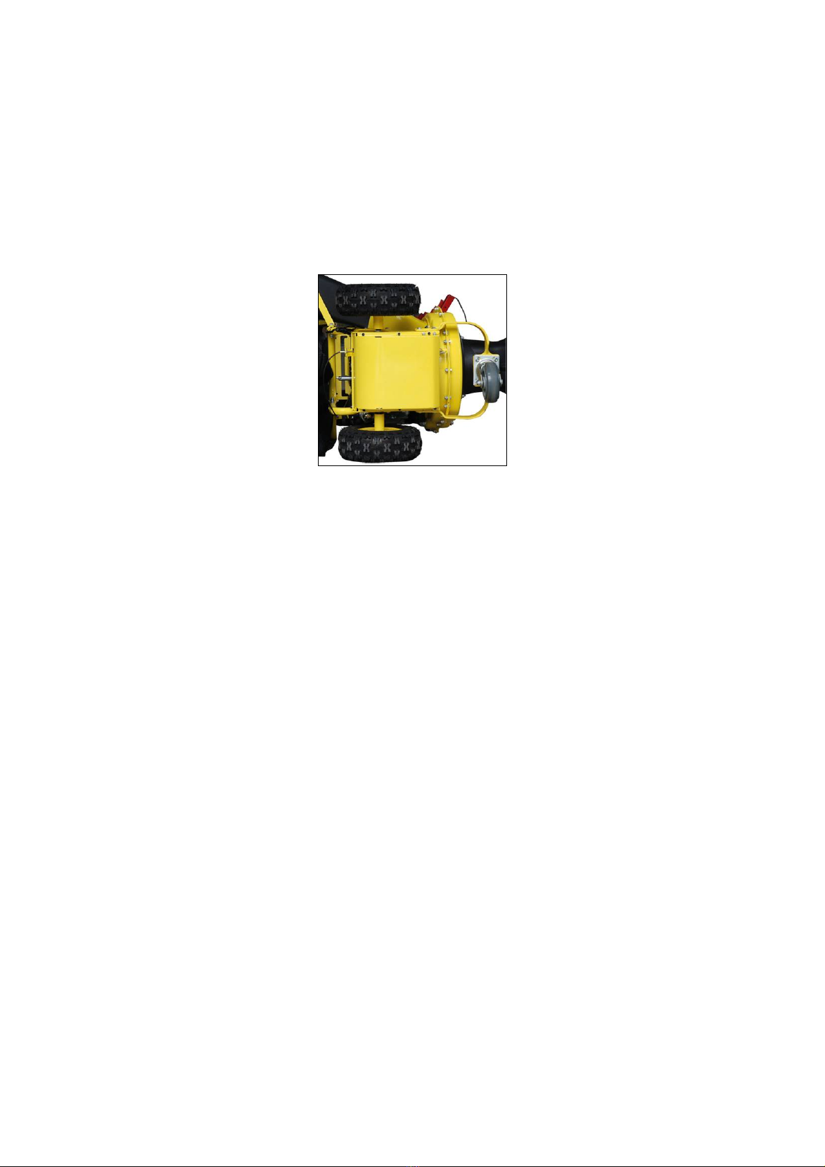
.Remove the plastic cover and metal cover from front of the engine by
removing the screws.
. Tip the unit backward so that it rests on the handles.
.Remove the lower guard of the gear box by removing the screws, See
Figure 11
Figure 11
. Remove the impeller (front) by removing the screws.
.If old belt cannot remove from the unit, cut and remove it.
.Insert new belt between “V” pulley of the clutch and the transmission
pulley of the engine.
.It is a little harder to load new belt because of its tightness. Press down
the V belt and rotate impeller to place new belt into slot on the pulley.
Pay attention not to put your hands between V belt and pulley to avoid
injury.
. Press down on the belt guard spring by the idler pulley, and adjust the
spring.
. Turn the impeller assembly counterclockwise to place the belt into the
slot on the impeller. Make sure the belt is routed inside all belts guards.
.Reassemble the flail screen, discharge chute, nozzle and the bag. (For
reassembly, follow instructions in previous page in reverse order.)
Storing Your Yard Vacuum
Clean the equipment thoroughly.
a. Wipe equipment with an oiled rag to prevent rust.
b. Refer to engine manual for correct engine storage instructions.
c. Store unit in a clean, dry area. Do not store next to corrosive material
such as fertilizer.
WARNING: Never store the machine or fuel container indoors where there is an
open flame, spark, or pilot light such as on a water heater, furnace, clothes dryer,
or other gas appliance.

Trouble shooting
Problem
Cause
Remedy
Engine fails to
start
1. Spark plug wire disconnected.
2Choke not in CHOKE position (if
equipped).
3. Fuel tank empty or stale fuel.
4. Engine not primed (if equipped).
5. Faulty spark plug.
6. Blocked fuel line.
7. Engine flooded.
1. Connect wire to spark plug.
2. Make choke lever to CHOKE
position.
3. Fill tank with clean, fresh
gasoline.
4. Prime engine as instructed in
Engine Manual.
5. Clean, adjust gap, or replace
6. Clean fuel line.
7. Wait a few minutes to restart
the engine.
Engine runs
erratic
1.Spark plug wire loose.
2 Blocked fuel line or stale fuel.
1. Connect and tighten spark
plug wire.

3. Vent in gas cap plugged.
4. Water or dirt in fuel system.
5. Dirty air cleaner.
6. Carburetor out of adjustment
2. Clean fuel line fill tank with
clean, fresh gasoline.
3. Clear vent.
4 .Drain fuel tank. Refill with
fresh fuel.
5. Refer to engine manual.
6. See authorized service dealer.
Engine
overheats
1. Engine oil level low.
2. Drity air cleaner.
3. Carburetor not adjusted properly.
1. Fill crankcase with proper oil.
2. Refer to engine manual.
3. See authorized service dealer.
Occasional
skips
(hesitates) at
high speed
1.Spark plug gap too close
2. Carburetor idle mixture adjustment
improperly set.
1. Adjust gap to .030〞.
2. See authorized service dealer.
Excessive
Vibration
1. Loose parts or damaged impeller.。
1. See authorized service dealer.
Unit does not
discharge
1. Chute deflector clogged.
2. Foreign object lodged in impeller.
3. Low engine RPM.
4. Vacuum bag is full.
1. Stop engine immediately and
disconnect spark plug wire.
Clean flail screen and inside of
discharge opening.
2. Stop engine and disconnect
spark plug wire. Remove
lodged object.
3. Always run engine at full
throttle.
4. Empty bag.
Rate of
discharge
slows
Considerably
or composition
of discharged
material
changes
1.Low engine RPM.
2. Chipper blade dull.
1. Always run engine at full
throttle.
2. Replace chipper blade or see
authorized service dealer.
For parts and /or accessories please see local authorized service dealer.


No
Description
Material
Spec
Qty
No
Description
Material
Spec
Qty
1
lever
1
41
axes spring ring
35
3
2
nozzle
1
42
rear wheel axes 2#
1
3
hex bolt
M12*13
0
2
43
big gear
QT600-3
1
4
rear wheel
19〞
2
44
spring roll pin
6*12
4
5
hemicycle pin
2
45
bottom cover
Steel Q235
t2
1
6
axle long bush
F0113J
2
46
tray spring bracket
Steel Q235
t3
1
7
axle short bush
F0113J
2
47
spring
1
8
hex bolt
M8*12
2
48
impeller case(rear)
cold rolled steel
Q235
t2
1
9
discharge tube
1
49
friction wheel
1
10
impeller case(front)
cold rolled steel
Q235
t2
50
spring roll pin
4*14
1
11
screen
1
51
small gear axes
hard-drawn hex steel
45#
1
12
impeller
cold rolled steel
Q235
t4
52
hex bolt
M6*10
2
13
blade
W18Cr4V
2
53
slide bearing
1
14
hex bolt
M8*40
few
54
position control
cover
POM
1
15
gear board 2
cold rolled steel
Q235
t3
1
55
V-wheel with clutch
1
16
connector
cold rolled steel
65Mn
t2
1
56
inner hex screw
round steel 35#
M8*25
6
17
gear adjust handle
1
57
hammer axes
round steel 45#
Ø15
2
18
bag
1
58
V-belt
1
19
hex bolt
M6*50
1
59
hammer
ZG270-500
2
20
throttle control lever
1
60
blade press ring
steel Q235
t3
1
21
manipulate
controller
1
61
spring roll pin
3*16
2
22
switch
1
62
hex bolt
M8*20
4
23
tamper plug
1
63
front wheel bracket
ZG270-500
1
24
handle
welded steel
tubeQ235
Ø28*2
1
64
flat gasket
8
few
25
side chute 1
1
65
hex bolt
M8*12
few
26
side chute bracket
cold rolled steel
Q235
t1.5
1
66
nozzle gasket
PP
1
27
side chute 2
cold rolled steel
Q235
t1.5
1
67
hex bolt
M8*35
4
28
seat
t4
1
68
hex bolt
M12*10
0
1
29
tension wheel spring
65Mn
1
69
flat gasket
8
3

30
tension wheel
support
cold rolled steel
Q235
t3
1
70
wheel
1
31
tension wheel
PP
1
71
nut
M12
3
32
blade cover plate
cold rolled steel
Q235
t1.5
1
72
nozzle support plate
cold rolled steel
Q235
t2
2
33
impeller case
supporter
ZG270-500
1
73
leaf collect plate
neoprene
1
34
impeller bracket
steel 45
t3
1
74
nozzle support
angle
cold rolled steel
Q235
t2
2
35
gear case body
steel Q235
1
75
flange nut
M6
2
36
bracket
cold rolled steel
Q235
t2
1
76
flat gasket
6
few
37
connect bar
1
77
spiral bolt
M6*25
4
38
hemicycle key
5*7.5*1
9
1
39
bearing
3202Z
2
40
gear case bearing
FZ1265
5*21
2
Table of contents


