Toolex Industrial 595185 User manual


Page 1
EC Declaration of Conformity
According to the Machinery Directive 2006/42/EC
For the following equipment:
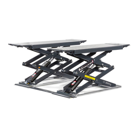
Product : Scissor Lifting Table
Type Designation /Trademark :595185
Manufacturers Name :Toolex Industrial
Manufacturers Address :PO Box 1012 Hamilton NSW 2303 Australia
Refer to in this declaration conforms to the following directive(s):
Machinery Directive 2006/42/EC
The company named above will keep on file for review the following technical documentation:
•Operating and maintenance instructions
•Technical drawings
•Risk assessment
•Description of measures designed to ensure conformity
•Other technical documentation ,e.g. quality assurance measures for design and production

Page 2
Ⅰ.Configuration diagram
II. Main technical parameters:
Model
595185
Capacity kg
300/500
Max. lift height H mm
900
Min. height of table h mm
280
Table size mm
815×500×50
Handle height A mm
996
Overall length B mm
942
Foot pedal cycles to max. height
≤32/≤45
Wheel diameter D mm
127
Working volume of oil cylinder ml
164
Oil capacity ml
250
Service weight kg
75/85
noise level dB
<70
III. Scope of application:
SP series table lift truck is a kind of high-lift transportation tool which is applicable for short-distance transportation as well as goods lifting and
lowering. Besides, it can also be used as station facilities for workshop.
IV. Operation condition:
1. Lift table should be operated on solid and flat ground;
2. Operation temperature: -20-40C°.
V. Notes (warning) :
1. Read the instruction carefully before operation and get to know the performance and operation requirements of the lift table. And the hydraulic lift
table can’t be used unless it is authorized.
2. Do not overload the hydraulic lift table and operate it within the rated load. Overloading will cause damage to the hydraulic lift table and human
body.
3. It is forbidden for operators to stand or sit on the table to work.
4. Don’t put the hands or feet under the lowering table.
5. Please brake the truck when loading goods to prevent it from moving.
6. Off-set loading is forbidden when loading goods, and the goods should be distributed uniformly on the whole table.
7. Loose or unstable goods are not permitted to be loaded.
8. Don’t put goods on working table for a long time.
9. The truck can’t be moved when goods are being lifted.
10. The truck can only be moved on flat and hard ground, it is forbidden to be used on sloping ground or rugged ground;
11. When putting goods on table which has been hoisted, the weight of goods should be within rated load, and the goods should be loaded lightly.
(Safety valve only works in hoisting process, if the truck has been hoisted, and then put overweight goods on it, the safety valve can’t work. In
this way, the truck may be damaged.)
12. When loading and unloading goods on hoisted table, don’t drag goods in cross direction, which may cause serious off-set loading and make truck
turn over.

Page 3
13. When maintaining and repairing truck, stand bar should be used to support fork arm in order to prevent table from falling (there should be no
goods on table), and guarantee the safety in maintenance and repairing.
14. Please operate strictly according to “notes (warning)”, otherwise it will bring damage to truck and human body.
VI. Operation methods:
1. Please step on the foot lever for several times to raise the working table.
2. Please lift the handle knob upward slowly, and open the one-way valve to make the working table descend slowly.
3. Please make the brake open before moving the truck.
VII. Maintenance and upkeep:
It is very important to conduct necessary maintenance and upkeep so as to prolong the service life and safety of the lift table. Please check the lift
table before operation according to the following items:
1. Whether there is any distortion and bending of various positions of the lift table.
2. Please check the brake of the truck and the wearing condition of the wheels.
3. Check oil leakage in the hydraulic system.
4. Please add or fill lubricant to each friction surface before daily operation.
5. If there is any failure, the lift table should be repaired at once, then it can be put into use again.
6. Chang the hydraulic oil every twelve months, choose the following or close brand hydraulic oil according to the climate conditions of different areas:
a) YBN32 is adaptive under the environment temperature of -10~+40°C;
b) YCN32 is adaptive under the environment temperature of -20~+40°C.
7. Hydraulic oil change methods:
a) Screw out the sealing screw 11 of the attached drawing (2) with wrench;
b) Raise the hand knob;
c) Twist off screw 36 of the oil plug and fill in hydraulic oil.
8. No.1, no.3, no.4, no.21, no.29, no.32, no.40, no.43, no.47, no.48, no.33, no.41 and no.45 of attached drawing (2) are seal components of rubber,
polyurethane and nylon. The general keeping time is two years. If exceeding the time limit, it will be aging and this will affect the service
performance. If so, please change it in time.
VIII. Trouble shooting methods (refering to drawing 2)
Faults
causes
Trouble shooting
The truck cannot
be raised or the
lifting height is
not enough.
1) Steel ball (23) of the
check-valve is not closed
down.
2) Firing pin (28) withstands
the steel ball (16).
3) Short of hydraulic oil.
1) Clean the valve opening and change the
steel ball (23).
2) Adjust the tension rate of the steel wire
rope to make firing pin at suitable place,
and add or fill lubricant to the pin roll(30)
3) Add enough hydraulic oil.
The table-board
rises then
descends.
1) Steel ball (23) (24) (16) of
the check-valve is not
closed down.
2) Firing pin (28) withstands
the steel ball (16).
1) Clean the valve opening and change the
steel ball (23) (24) (16).
2) Adjust the tension rate of the steel wire
rope to make firing pin at suitable place,
and add or fill lubricant to the pin roll(30)
The table-board
does not
descend
The travel of the firing pin
(28) is not enough to open
the steel ball (16).
Adjust the tension rate of the steel wire rope
to make firing pin at suitable place, and add
or fill lubricant to the pin roll(30)
Oil leakage at
firing pin.
The O-ring (29) is damaged.
Change the o- ring (29).
Oil leakage at
pump (2), pump
core (5) and
piston rod (44).
The seal ring (1) (3) (47)
(48) are damaged.
Change the seal ring (1)(3)(47)(48)
IX. Assembly method (refering to drawing 1) :
(I) 595185 type trucks are folding type. Only if the handle is pulled up, this series truck can be operated.
(II) The handle and foot lever of SP300A, SP500A type lift table are dismantled when ex-factory, they might be fixed together by the users when
using. The assembly methods are as follows:
Handle installation method: according to the developed drawing, fix the handle (1) to mounting hole of the truck body (18) with bolt (64), spring
washer (63), flat washer (62), and then screw down the bolt (64) with wrench.
Foot lever mounting: insert the foot lever (47) into the hole of the square bar (60), screw in the screw (42), then put in the plain washer (6) and
the spring washer (11) respectively and screw down the nut (12).
X. Structure diagram and principle diagram

Page 4
See the principle diagram of the hydraulic system in the attached drawing (3)
Attached drawing (1)
Attached drawing (2)

Page 5
Attached drawing(3)
Principle specification
1. The restriction chock and the constant pressure
overflow valve leak oil at the same when no-load,
the no-load vehicle descend faster, and it can meet
the customers the demand。
2. When the load is more than 50kg, the system
pressure is 8MPa, the constant pressure overflow
valve closes automatically, the hydraulic oil leaks
through the restriction chock, the vehicle descend
slowly, and this agrees with the safety standards.
Unloading valce
Oil reservoir
Safety valve
One-way valve
One-way valve
e
Oil pump
Working cylinder
Throttle valve

Page 6
Spare parts catalogue
1. Explosive drawing and parts list of handle
2. Explosive drawing and parts list of 595185 pump
3. Explosive drawing and parts list of 595185 assembly

Page 7
Explosive Drawing and Parts List of Handle
No.
Drawing no.
Description
Qty.
Remark
1
Spring pin 6x30
GB879-86
1
2
Handle bar
SPAⅢ.1.01
1
3
Knob
SPⅢ.1.02
1
4
Nut M8
GB6172-86
1
5
Screw
SPⅢ.0-01
1
6
Pull rod
1200(1020)
1

Page 8
Explosive Drawing of 595185 pump

Page 9
Parts List of 595185 pump
No.
Drawing no.
Description
Qty.
Remark
1
GB3452.1-86
0-ring 22.4×2.65
1
2
SP.8-11A
Pump cylinder
1
SP500(A)
SP.8-11
Pump cylinder
1
SP300(A)
3
UHS18
Yx- seal ring
1
300KGS
UHS14
Yx- seal ring
1
500KGS
4
DH18
Dust ring
1
300KGS
DH14
Dust ring
1
500KGS
5
SP.8-10
Pump plunger
1
300KGS
SP.8-10A
Pump plunger
1
500KGS
6
SP.8-09
Spring
1
7
SP.8-08
Spring seat
1
8
GB894.1-86
Retaining ring for axle 10
1
9
SP.0-13B
Joint plate
2
10
SP.0-14
Pin
1
11
JF.1-17
Screw
1
12
JB982-77
Copper washer 20
1
13
6W804.1-12
Damp valve
1
14
YQ-03
Spring
1
15
YQ-02
Spring seat
1
16
GB308-77
Steel ball 6.35
2
17
GB308-77
Steel ball 4.5
1
18
SP.8-18
Spring seat
1
19
SP.8-17
Spring
1
20
SP.8-16
Adjusting screw
1
21
GB3452.1-86
O-ring 7.5×2.65
2
22
SP.8-15
Cover ring
1
23
GB308-77
Steel ball 9.5
1
24
SP.8-07
Spring
1
25
GB308-77
Steel ball 1/2 (12.7)
1
26
GB77-85
Screw M16×18
1
27
YQ-01
Strike pin
1
28
GB3452.1-82
0-ring 6.9×1.8
2
29
DF1.2-08
Shaft
1
30
Filter
1
31
GB3452.1-82
O-ring 65×3.55
1
32
SP.8-12
Rectangular ring section
1
33
SP.8-04
Cylinder
1
34
SP.8-03
Housing
1
35
SP.8-02
Screw
1
36
GB894.1-86
Retaining ring for axle 25
1
37
SP.8-13
Washer
1
38
GB3452.1-82
O-ring 33.5×3.55
1
39
SP.8-14
Cup packing
1
40
SP.8-06
Bush
1
41
GB3452.1-82
O-ring 20×2.65
1
42
SP.8-05
Piston rod
1
43
CO1.2-16
Rectangular section sealing
1
44
SP.8-01
Cylinder cap
1
45
GB3452.1-82
O-ring 31.5×3.55
1
46
HG4-692-67
J Shaped steel frame rubber sealing
32×45×6.5
1
47
YQ.6-300
Base
1
48
YQ-04
Lever plate
1
49
GB894.1-86
Retaining ring for axle 8
1

Page 10
Explosive drawing of 595185 assembly

Page 11
Parts List of 595185 assembly
No.
Drawing No.
Description
Qty.
Remark
2
SP.1-00
Handle bar
1
3
GB5781-2000
Bolt M8×25
12
4
GB95-1985
Washer 8
25
5
GB93-1987
Washer 8
13
6
GB41-86
Nut M8
13
8
Universal Wheel 5″
2
SP.4-00
9
SPC.5-00
Frame
1
10
SP.0-08
Shaft
2
11
SP.0-04
Wheel 5”
2
12
GB894.1-86
Retaining rng for axle 12
2
14
SP.0-11
Shaft
1
15
SP.0-12
Bush
1
16
GB894.1-86
Retaining ring for axle 10
1
17
SPS.0-03
Shaft
1
18
YQ-7
Retaining ring
1
19
GB894.1-86
Retaining ring for axle 20
2
20
SP.3.04B
Connecting rod
1
21
SP.3-03
Cushion
1
22
GB5781-2000
Bolt M8×30
1
23
SP.3-02
Pedal bar
1
Rubber cover
24
SPC.7-00
Table
1
25
GB894.1-86
Retaining ring for axle 16
6
26
GB848-1985
Washer 16
4
27
SP.6-12
Washer
2
28
SP.6-11
Washer
2
29
SP.6-10
Roller
2
30
SP.6-01
Bush
2
31
SP.0.02
L-pin
4
32
GB70-85
Bolt M6×10
4
33
SP.0-03
Shaft
1
34
SPC.6-00
Arm
1
35
SF-1.1612
Bush
2
40
YQ-00-500
Pump
1
41
SPC.6-07
Support
2
42
SPA.4-07
Washer
2
43
GB894.1-86
Retaining ring for axle 24
2
44
GB93-1987
Washer 6
4
46
YQ-8
Retaining ring
1
47
SP.0-06
Bush
4
48
SP.0-07
Hollow shaft
2
49
GB276-86
Bearing 6203
4
Table of contents
