Toolkraft 910A Use and care manual
·OPERATING
INSTRUCTIONS
AND
PARTS LIST
BEFORE
ATTEMPTING TO
DO
ANY
WORK
WITH YOUR RADIAL ARM SAW
READ
THESE
INSTRUCTIONS
CAREFULLY
-
MODEL
910A
THE
ABOVE MODEL NUMBER
IS
ON
THE
NAMEPLATE OF YOUR MACHINE
Always
use
this
Number
and
Serial
Number
in
correspondence
with
us
regarding
this
machine
or
when
ordering
parts.
HOW
TO
ORDER
PARTS
All
parts
can be ordered from the factory.
Always include the information below when ordering
parts:
1.
The
Part
Number
in this list
(not
the Index Number).
2.
The
Part
Name
in this list.
3.
The Model
Number
and
Serial
Number
of
your machine.
4.
The color
of
painted parts.
THIS
LIST
WILL
BE
VALUABLE
TO YOU
IN
ORDERING
SERVICE
PARTS
OR ACCESSORIES-DO
NOT
THROW IT AWAY
TOOLKRAFT CORPORATION,
700
PLAINFIELD
STREET,
SPRINGFIELD,
MASSACHUSETTS
your
desired position
on
the
be\el
tilt scale. Index pin automatic-
ally locates
0°,45°,90°
and
180°. ALWAYS
LOCK
THIS
CLAMP
BEFORE
MAKING
ANY
CCTS.
U.
Work
Table-For
adjustments see TABLE
ADJUSTMENT
under
ASSEMBLY AND ADJCST:\1E.....
TS
section
and
section
on
COVERING
THE
TABLE
TOP.
V. Column
Adjustment-See
TO
RE:\10VE
PLAY
FROM
PED-
ESTAL
under
ADJUSTME:\TS
TO
CO"-1PENSATE
FOR
WEAR.
W. Gib
Adjustment-See
TO
RE:\10VE
SIDE
PLAY
FROM
UPPER
ARM
under ADJUST"-iE:'\TS
TO
CO:\fPE:\SA
TE
FOR
WEAR.
X. Sawdust
Discharge-Rubber
sa",duSI discharge
can
be easily
turned
to
direct sawdust away from work and operator.
Y. Yoke Clamp
and
Index
Pin-These
controls are used to turn
and
lock the yoke horizontally
on
the carriage.
To
move the. yoke,
push the clamp handle
to
your
right, pull up on the index pm a':ld
turn
the yoke to
your
desired location. The index pin automatic-
ally locates cutoff, in rip
and
out
rip positions. ALWAYS LOCK
THIS
CLAMP
BEfORE
:\1AKI:\G A
...
"1'
CLTS.
Z.
Anti Kickback and
CIamp-
The anii kickback should be used in
all tipping operations. The kickbac. grips should hang
Vs"
below
the
top
of
the work
to
function
properi~.
Set the height by loosen-
ing the clamp screw, pushing the kickback rod up
or
down as
necessary
and
locking Ihe clamp scre"'.
AA. Inner Arbor Collar
Wrem:h-
Tnl;
wrench should be used with a
1~6
wrench (Toolkraft
X\I-215
.see accessory list under Blades)
for removing the saw blade. Sli the Inner
arbor
collar wrench
onto
the inner
arbor
collar until
the
ends slip into the holes
on
each side.
Turn
the
arbor
nut
'ilh
~o
r
"1;
"'rench clockwise
to
loosen
and
counterclock"'lsc
to
lighten.
BB. Adjustment
Keys-These
hex
ke~
sare
to
be
u.><:d
for the adjust-
ments described under
.-\DJCST\lE:\iS
TO
COMPENSATE
FOR
WEAR and under ASSE..'\fBLY.-\:\D
:\DJCSTING
sections.
FIGURE
2
"'-=--'''"''41''
~~--_H-SWfTCH
1
-tJIPfER
ARM
"-rOM"tR
LOCJ\
K-~~Nl
SCREWS
I
L-A,IP5CAl.E t
M-CARRtAGE
CLAW
i'
r-------,...------
..
-~"'f~
.....
!
FIGURE
1
C-eARRI.'o<>E:-----
NOT£'
REF£R TOMRT.s
LIST
fOIl
ORDERING
""'1S
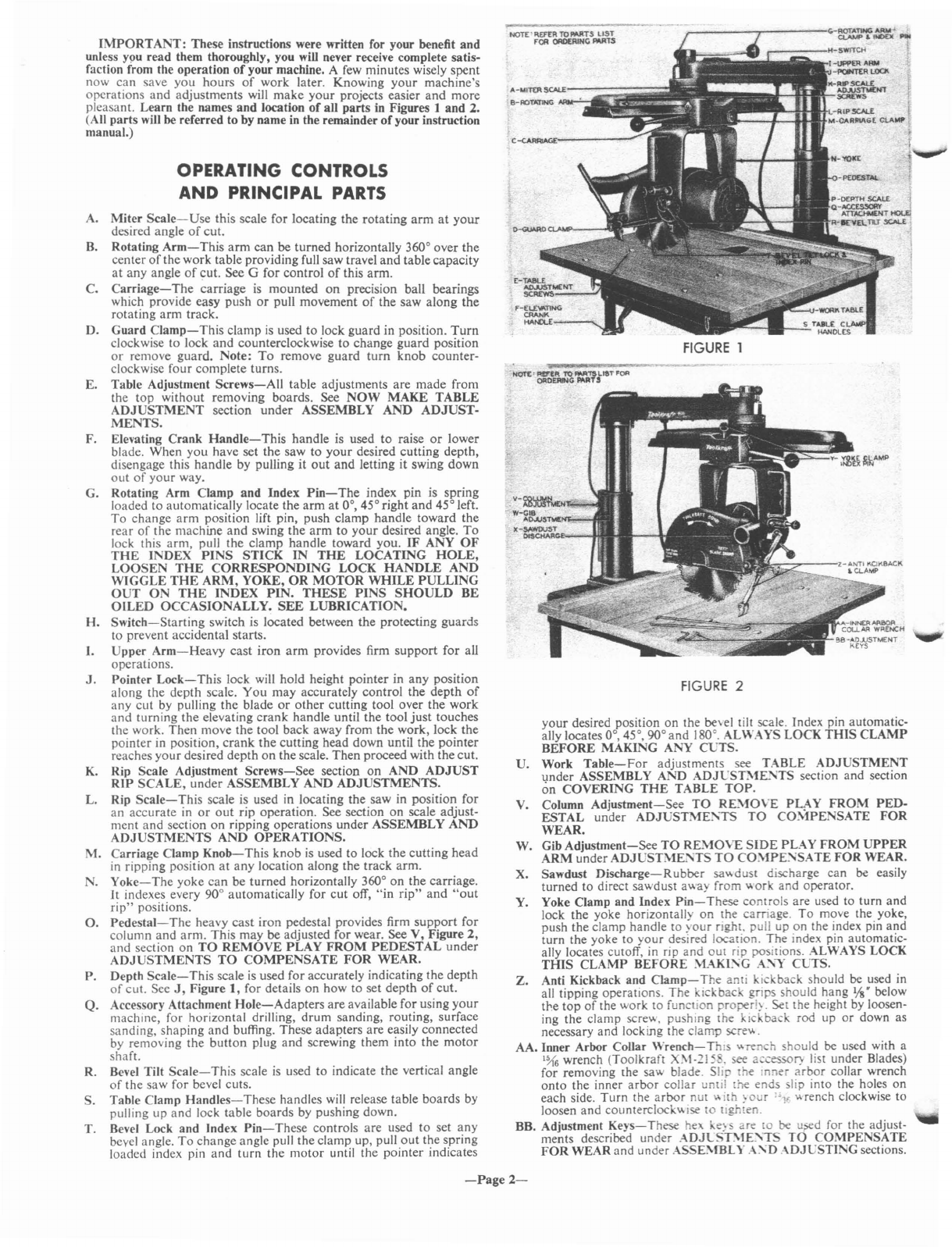
OPERATING CONTROLS
AND PRINCIPAL
PARTS
IMPORTANT:
These instructions were written for your benefit
and
unless
Y9U
read them thoroughly, you will never receive complete satis-
faction from the operation
of
your machine. Afew minutes wisely spent
now
can
save
you
hours
of
work later. Knowing
your
machine's
operations
and
adjustments will
make
your
projects easier
and
more
pleasant. Learn the names
and
location
of
all
parts
in Figures 1
and
2.
(All
parts
will be referred to by name in the remainder
of
your instruction
manual.)
A.
Miter
Scale-Use
this scale for locating the
rotating
arm
at
your
desired angle
of
cut.
B.
Rotating
Arm-This
arm
can
be
turned
horizontally 360° over
the
center
of
the work table providing full saw travel
and
tablecapacity
at
any angle
of
cut.
See Gfor
control
of
this
arm.
C.
Carriage-
The
carriage is
mounted
on
precision ball bearings
which provide easy push
or
pull movement
of
the saw along
the
rotating
arm
track.
D.
Guard
Clamp-This
clamp
is
used
to
lock guard in position.
Turn
clockwise
to
lock
and
counterclockwise
to
change
guard
position
or
remove guard. Note:
To
remove
guard
turn
knob
counter-
clockwise
four
complete turns.
E. Table Adjustment
Screws-All
table adjustments are
made
from
the
top
without removing boards. See
NOW
MAKE
TABLE
ADJUSTMENT
section
under
ASSEMBLY
AND
ADJUST-
MENTS.
F. Elevating
Crank
Handle-This
handle is used
to
raise
or
lower
blade. When
you
have set
the
saw
to
your
desired cutting depth,
disengage this
handle
by pulling
it
out
and
letting
it
swing
down
out
of
your
way.
G. Rotating Arm Clamp
and
Index
Pin-The
index pin is spring
loaded
to
automatically locate the
arm
at
0°, 45° right
and
45° left.
To
change
arm
position lift pin, push clamp handle toward
the
rear
of
the machine
and
swing
the
arm
to
your
desired angle.
To
lock this
arm,
pull
the
clamp
handle
toward you.
IF
ANY
OF
THE
INDEX
PINS
STICK
IN
THE
LOCATING
HOLE,
LOOSEN
THE
CORRESPONDING
LOCK
HANDLE
AND
WIGGLE
THE
ARM,
YOKE,
OR
MOTOR
WHILE
PULLING
OUT
ON
THE
INDEX
PIN.
THESE
PINS
SHOULD
BE
OILED
OCCASIONALLY.
SEE
LUBRICATION.
H.
Switch-Starting
switch is located between
the
protecting
guards
to prevent accidental starts.
I.
Upper
Arm-Heavy
cast
iron
arm
provides firm
support
for
all
operations.
J.
Pointer
Lock-This
lock will hold height pointer in
any
position
along the depth scale.
You
may
accurately
control
the
depth
of
any
cut
by pulling the blade
or
other
cutting tool over the work
and
turning the elevating
crank
handle until
the
tool
just
touches
the work.
Then
move
the
tool back away from
the
work, lock
the
pointer in position,
crank
the
cutting head down until the
pointer
reaches
your
desired depth
on
the scale.
Then
proceed with the cut.
K. Rip Scale Adjustment
Screws-See
section
on
AND
ADJUST
RIP
SCALE,
under
ASSEMBLY
AND
ADJUSTMENTS.
L. Rip
Scale-This
scale is used in locating the saw in position for
an
accurate
in
or
out
rip operation. See section
on
scale adjust-
ment
and
section
on
ripping operations
under
ASSEMBLY
AND
ADJUSTMENTS
AND
OPERATIONS.
M.
Carriage Clamp
Knob-This
knob
is
used to lock
the
cutting
head
in ripping position
at
any
location along the track arm.
N.
Yoke-The
yoke
can
be turned horizontally 360°
on
the
carriage.
It
indexes every 90° automatically for
cut
off,
"in
rip"
and
"out
rip"
positions.
O.
Pedestal-The
heavy
cast
iron
pedestal provides firm
support
for
column
and
arm.
This may be adjusted for wear. See V, Figure
2,
and
section
on
TO
REMOVE
PLAY
FROM
PEDESTAL
under
ADJUSTMENTS
TO
COMPENSATE
FOR
WEAR.
P. Depth
Scale-This
scale
is
used for accurately indicating
the
depth
of
cut. See
J,
Figure
1,
for details
on
how to set depth
of
cut.
Q.
Accessory Attachment
Hole-Adapters
are
available for using
your
machine for horizontal drilling,
drum
sanding, routing, surface
sanding,'shaping
and
buffing. These adal?ters
are
easily connected
by removing the
button
plug
and
screwing them
mto
the
motor
shaft.
R. Bevel Tilt
Scale-This
scale
is
used
to
indicate the vertical angle
of
the saw for bevel cuts.
S. Table Clamp
Handles-These
handles will release table
boards
by
pulling up
and
lock table boards by pushing down.
T. Bevel Lock and Index
Pin-These
controls are used
to
set
any
bevel angle.
To
change angle pull
the
clamp up, pull
out
the spring
loaded index pin
and
turn
the
motor
until the pOinter indIcates
-Page
2-
WORKING
FLEXIBILITY
Figures 3
and
4
illustrate
the working flexibility
of
your
radial
arm
saw. An infinite
number
of
working
arrangements
may
be set
up
quickly
and
easily.
The
rotating
arm
can
be
turned
horizontally
360°
directly
ovcr
the
center
of
the
work
table.
The
index pin
automatically
locates 45° right
hand
miter.
0°
cross-cut.
and
45° left
hand
miter
culting
positions.
It
can
be
locked
in
any
position
around
the
360°.
The
cUlting head
can
be
moved
to
any
location
along
the
rotating
ann
track
and
locked.
The
yoke
turns
360°
horizontally
on
the
carriage.
indc\cs
automatically
every
90°
and
may
be locked
at
any
horizontal
location
under
the
carriage.
The
saw
arbor
can
be
swung
afull 180°
(90'
down
from
the
horizontal
cutting
position
and
90°
up
from
the
horizontal
cutting
position). Bevel index pin
automatically
locates 0°.
45 .90°.
and
180°.
The
saw
arbor
can
be locked in
any
bevel
location
bet\\een
0°
and
180°.
ASSEMBLY
AND
ADJUSTMENTS
Every
Toolkraft
machine is thoroughly
tested,
inspected
and
aligned
at
the factory. However,
minor
adjustments
might be necessary because
rough handling
in
shipment
or
unpacking
may have disturbed the set-
tings. Check
your
machine
carefully;
assemble the
carriage
and
motor
assembly; assemble the
table
parallel
to
the
rotating
arm;
make
sure
the blade is
square
to the
table
top,
the
cross
cut
blade travel is
square
to the fence,
and
the
blade
does
not heel.
FOLLOW
EACH
STEP
AS
WE
HAVE
OUTLINED
THEM
IN
THIS
SECTION.
FIRST
UNPACK:
Your
Toolkraft
Radial
Arm
Saw
is
shipped
assembled
except
for
the yoke
and
motor
assembly
and
the
work
table
assembly.
Remove
the
machine
from
the
box
and
be
sure
that
all
parts
have been
removed
from
the
packaging
before
discarding.
THEN
CLEAN:
Remove
protective
coating
from
rotating
arm
track
with
kerosene
or
\arsol.
INSTALL
YOKE
AND
MOTOR
ASSEMBLY:
Your
machine's
yoke
and
motor
are
packaged
in
the
small
carton
which
is
taped
to
the
base
center
support
bars.
Follow
the
steps
listed
below
to
install
this
assembly.
I.
Remove
the
name
plate
from
the
front
of
the
rotating
arm
and
the
small
carriage
safety
stop
bolt
from
the
front
bottom
right
hand
side
of
the
track.
~
Install
the
elevating
crank
handle
and
raise
the
column
and
arm
as
far
as
it will
go.
3.
Cut
open
the
carton
and
the
nylon
tape
straps
holding
it in place.
The
mounting
bearings
have
been
completely
adjusted
at
the
fac-
tory.
Just
lift
the
entire
assembly
and
slide it
onto
the
arm.
of.
Replace
the
name
plate
and
the
carriage
safety
stop
bolt.
5.
Tilt
the
motor
to
the
0°
position
by
loosening
the
bevel tilt lock.
pulling
out
the
bevel
index
pin
and
tilting
the
motor
by
hand.
6.
Install
the
saw
blade
and
guard.
(See
Figure
10
for
proper
direction
of
teeth.)
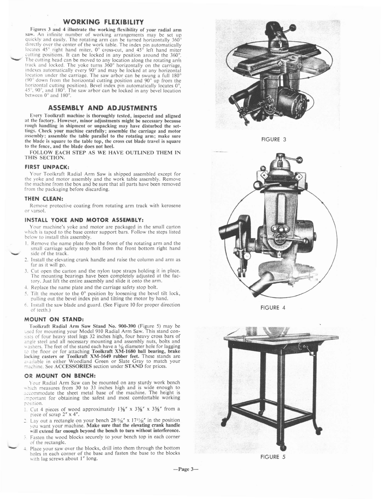
MOUNT
ON
STAND:
Toolkraft
Radial
Arm
Saw
Stand
No. 900-390
(Figure
5)
may
be
_sed for
mounting
your
Model
910
Radial
Arm
Saw.
This
stand
con-
S,SIS
of
four
heavy
steel legs 32
inches
high,
four
heavy
cross
bars
of
Ji1gk steel
and
all
necessary
mounting
and
assembly
nuts,
bolts
and
\\
rhers.
The
feet
of
the
stand
each
have
a
~6
diameter
hole
for lagging
'c'
[he floor
or
for
attaching
Toolkraft
XM-1680
ball bearing,
brake
locking
casters
or
Toolkraft
XM-1649
rubber
feet.
These
stands
are
.'\Jdable
in
either
Woodland
Green
or
Slate
Gray
to
match
your
,,:'achll1e. See
ACCESSORIES
section
under
STAND
for
prices.
OR
MOUNT
ON
BENCH:
)
our
Radial
Arm
Saw
can
be
mounted
on
any
sturdy
work
bench
\\
~Ich
measures
from
30
to
33 inches high
and
is
wide
enough
to
_,:.:,'mmodate
the
sheet
metal
base
of
the
machine.
The
height is
--;:,ortant for
obtaining
the
safest
and
most
comfortable
working
:'
........
s!tion.
Cut
4pieces
of
wood
approximately
I
Ys"
x
3Ys"
x3Ys'
from
a
"iece
of
scrap
2" x4".
•
Layout
a
rectangle
on
your
bench
281~6"
x17')16' in
the
position
\
au
want
your
machine.
Make
sure
that
the elevating
crank
handle
~
ill
extend
far
enough beyond
the
bench
to
turn
without interference.
Fasten
the
wood
blocks
securely
to
your
bench
top
in
each
corner
of
the
rectangle.
-
!.
Place
your
saw
over
the
blocks,
drill
into
them
through
the
bottom
holes in
each
corner
of
the
base
and
fasten
the
base
to
the
blocks
\\
ith lag screws
about
I"
long.
-Page
3-
FIGURE
3
FIGURE 4
FIGURE
5

FIGURE
6
FIGURE
7
ADJUSTING
SCREW
;{zoxI
HE
ADLE
SS
SET
SCREW
SECTION
ON
BE
FIGURE
8
NEXT,
ASSEMBLE
TABLE:
I.
Because
of
wood's
natural
tendency to
absorb
moisture,
your
table
boards
may
have become slightly warped
during
or
after
shipment.
Crank
the
saw
up far
enough
to slip table
boards
into position.
Lay the
boards
out
on
the table
support
with the fence
in
position
at the rear.
Empty
out
the cloth
bag
containing
the table adjusting
and
fastening screws
onto
atable
and
pick
out
:2
round
head screws
'"
long
and
2flat washers. Slip the I"
round
head screws with flat
washer
through
each
of
the
front
holes
in
the table
support
to hold
the table in place
and
tighten the table clamps. If
the
table
clamps
are
too
tight
or
too
loose, they
can
be adjusted by
changing
the
location
of
the
nuts
which set the clamping screws in position.
Check
with a
straight
edge for high spots
or
gaps
on
the table
surface.
Check
the length
of
the fence for straightness. Any section
of
the table which
is
not flat
should
be sanded
or
planed.
Sanding
can
be
done
with
Toolkraft
Rotary
Sander
No. 4004 and 900-440
Adaptor.
Planing
may
be
done
with Toolkraft
Rotary
Planer
No.
4060 and 900-440
Adaptor.
See
ACCESSORIES
section for price.
See
OPERATION
section for illustrations.
2.
After
checking
your
boards, loosen the table clamps and remove
all
boards
from the table
supports.
See Figs. 6
and
8for detail
of
adjustment
and
locking screw assembly.
From
the table adjusting
and
fastening screws, pick
out
4headless screws
I"
long (these are
your
adjustment
screws), 4
square
nuts
and
4sheet metal
nut
re-
tainers. Insert
the
nut into
the
sheet metal nut retainer, slide the
nuts
and
nut retainers between
the
table
support
and
sheet metal
base
at
the second
and
fourth
holes in from
the
front
on
each side
so
that
the
hole in the table
support
lines up with the hole in the
nut
retainer
and
nut.
Turn
the headless adjusting screws
through
the
holes in
the
table
support
angle
and
nut retainer into the
square
nut until
approximately
l/S"
of
the
screw
is
through
the
bottom
of
the
nut.
3.
Place the 8" wide table section
in
position
on
the front
of
the
table
support
angle
so
that
the holes line up
and
the previously
installed front
adjusting
5crews
come
through
the small holes.
The
counterbored
side
should
be facing up. See Fig.
9.
Put
one
of
the
FIGURE
9
four
Aat
washers into each
of
the
four
counterbored
holes. Slip the
two I" long round head screws into the two front holes
and
fasten
securely with lock washers
and
ht:x
nuts. See Fig.
6.
Slip the two
I
~"
long
round
head screws into the third hole from the front
on
each side.
Take
the two
square
nuts
and
two nut retainers and
fasten to the
I~"
round
head screws as shown
in
Figs. 6and
7.
Slip the two \1,4" long
round
head screws
through
rear holes
in
the
FIGURE
10
FIGURE
11
-Page
4-
tabie
support
and
base
and
install the
remaining
square
nuts
and
nut
retainers
as
shown
in Fig.
6.
Lay
the
remaining
table
sections
behind
the
S"
section
in
the following
order:
slotted
6" section,
4%"
section,
6"
section
and
fence.
Tighten
the
table
clamp
screws.
__
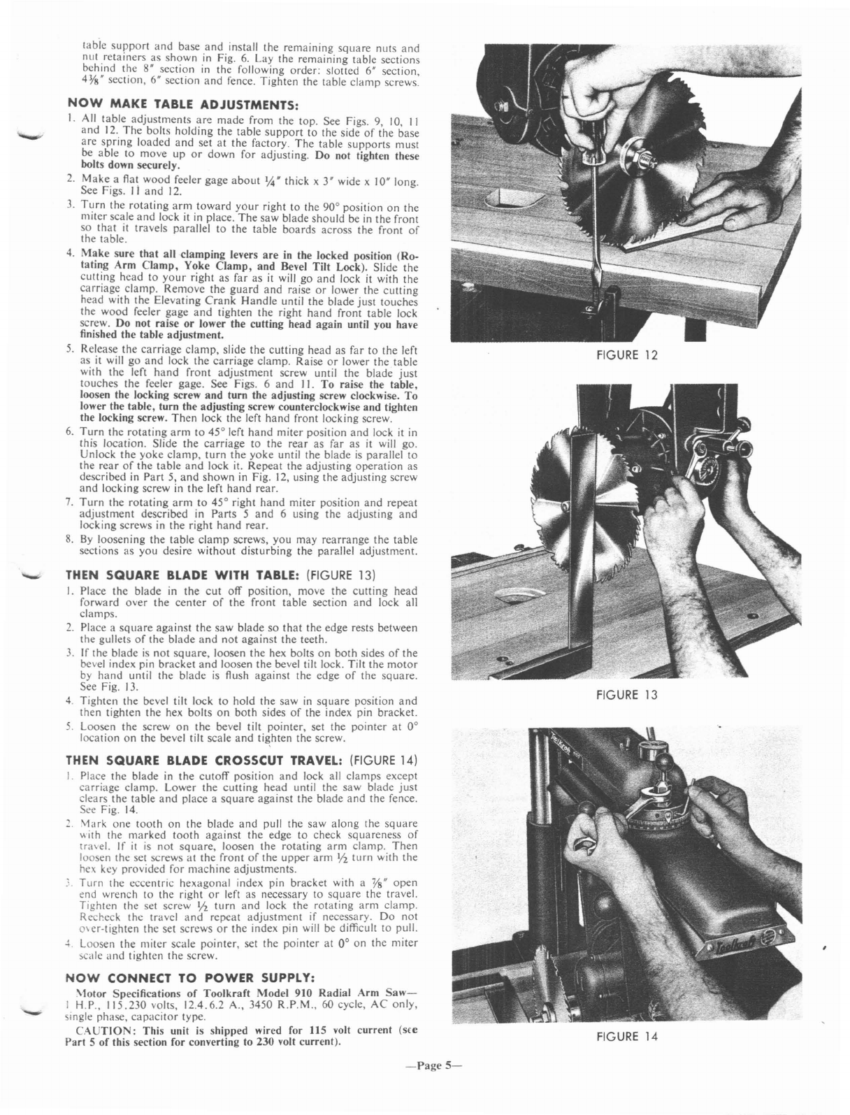
THEN SQUARE
BLADE
WITH
TABLE:
(FIGURE
13)
I.
Place
the
blade
in
the
cut
off
position,
move
the
cutting
head
forward
over
the
center
of
the
front
table
section
and
lock all
clamps.
2.
Place a
square
against
the
saw
blade
so
that
the
edge
rests between
the gullets
of
the
blade
and
not
against
the
teeth.
3.
If
the
blade
is
not
square,
loosen
the
hex bolts
on
both
sides
of
the
bevel index pin
bracket
and
loosen
the
bevel tilt lock. Tilt
the
motor
by
hand
until the
blade
is
flush
against
the
edge
of
the
square.
See Fig. 13.
4.
Tighten
the
bevel tilt lock
to
hold
the
saw
in
square
position
and
then
tighten
the
hex
bolts
on
both
sides
of
the
index pin
bracket.
5.
Loosen
the
screw
on
the
bevel tilt
pointer,
set
the
pointer
at
0°
location
on
the
bevel tilt scale
and
tighten
the
screw.
FIGURE
12
FIGURE
14
FIGURE
13
THEN SQUARE
BLADE
CROSSCUT TRAVEL:
(FIGURE
14)
I.
Place
the
blade
in
the
cutoff
position
and
lock all
clamps
except
carriage
clamp.
Lower
the
cutting
head
until
the
saw
blade
just
clears
the
table
and
place
a
square
against
the
blade
and
the
fence.
See Fig.
14.
2.
Mark
one
tooth
on
the
blade
and
pull
the
saw
along
the
square
"ith
the
marked
tooth
against
the
edge
to
check
squareness
of
tra\el.
If
it
is
not
square,
loosen
the
rotating
arm
clamp.
Then
loosen
the
set screws
at
the
front
of
the
upper
arm
Y2
turn
with
the
hex key
provided
for
machine
adjustments
.
..
Turn
the
eccentric
hexagonal
index pin
bracket
with a
Ys"
open
end
wrench
to
the
right
or
left
as
necessary to
square
the
travel.
Tighten
the set
screw
Y2
turn
and
lock
the
rotating
arm
clamp.
Recheck
the
travel
and
repeat
adjustment
if necessary.
Do
not
o\er-tighten
the
set screws
or
the
index pin will be difficult
to
pull.
J.
Loosen
the
miter
scale
pointer,
set
the
pointer
at
0°
on
the
miter
scale
and
tighten
the
screw.
NOW
CONNECT
TO
POWER SUPPLY:
\totor
Specifications
of
Toolkrafl
Model
910
Radial
Arm
Saw-
IH.P.,
115.230
volts,
12.4.6.2
A., 3450
R.P.M.,
60 cycle,
AC
only,
single
phase,
capacitor
type.
CAUTION:
This
unit is
shipped
wired for 115 voll
current
(s£e
Part
5
of
this section for converting to 230 voll
current).
NOW
MAKE
TABLE
ADJUSTMENTS:
1.
All
table
adjustments
are
made
from
the
top.
See Figs. 9, 10, II
and
12.
The
bolts
holding
the
table
support
to
the side
of
the
base
are
spring
loaded
and
set
at
the
factory.
The
table
supports
must
be
able
to
move
up
or
down
for
adjusting.
Do
not tighten these
bolts down securely.
2.
Make
aflat
wood
feeler
gage
about
'4" thick x3" wide x10" long.
See Figs.
II
and
12.
3.
Turn
the
rotating
arm
toward
yOur right
to
the
90°
position
on
the
miter
scale
and
lock it in place.
The
saw
blade
should
be in
the
front
so
that
it
travels
parallel
to
the
table
boards
across
the
front
of
the
table.
4.
Make
sure
that
all
clamping
levers
are
in the locked position
(Ro-
tating
Arm
Clamp,
Yoke
Clamp,
and
Bevel
Tilt
Lock). Slide
the
cutting
head
to
your
right
as
far
as
it will
go
and
lock
it
with
the
carriage
clamp.
Remove
the
guard
and
raise
or
lower
the
cutting
head
with
the
Elevating
Crank
Handle
until
the
blade
just
touches
the
wood
feeler
gage
and
tighten
the
right
hand
front
table
lock
screw.
Do
not
raise
or
lower the
cutting
head
again
until you have
finished the
table
adjustment.
5.
Release
the
carriage
clamp,
slide
the
cutting
head
as
far
to
the
left
as
it will
go
and
lock
the
carriage
clamp.
Raise
or
lower
the
table
with
the
left
hand
front
adjustment
screw until
the
blade
just
touches
the
feeler gage. See Figs. 6
and
)
1.
To
raise
the
table,
loosen the locking screw
and
turn
the
adjusting screw clockwise.
To
lower the
table,
turn
the
adjusting
screw counterclockwise
and
tighten
the locking screw.
Then
lock
the
left
hand
front
locking screw.
6.
Turn
the
rotating
arm
to
45°
left
hand
miter
position
and
lock
it
in
this
location.
Slide
the
carriage
to
the
rear
as
far
as
it
will
go.
Unlock
the
yoke
clamp,
turn
the
yoke
until
the
blade
is
parallel
to
the
rear
of
the
table
and
lock it.
Repeat
the
adjusting
operation
as
described in
Part
5,
and
shown
in
Fig. 12, using
the
adjusting
screw
and
locking
screw in
the
left
hand
rear.
7.
Turn
the
rotating
arm
to
45°
right
hand
miter
position
and
repeat
adjustment
described
in
Parts
5
and
6using
the
adjusting
and
locking
screws in
the
right
hand
rear.
S.
By
loosening
the
table
clamp
screws,
you
may
rearrange
the
table
sections
as
you
desire
without
disturbing
the
parallel
adjustment.
-
-Page
5-
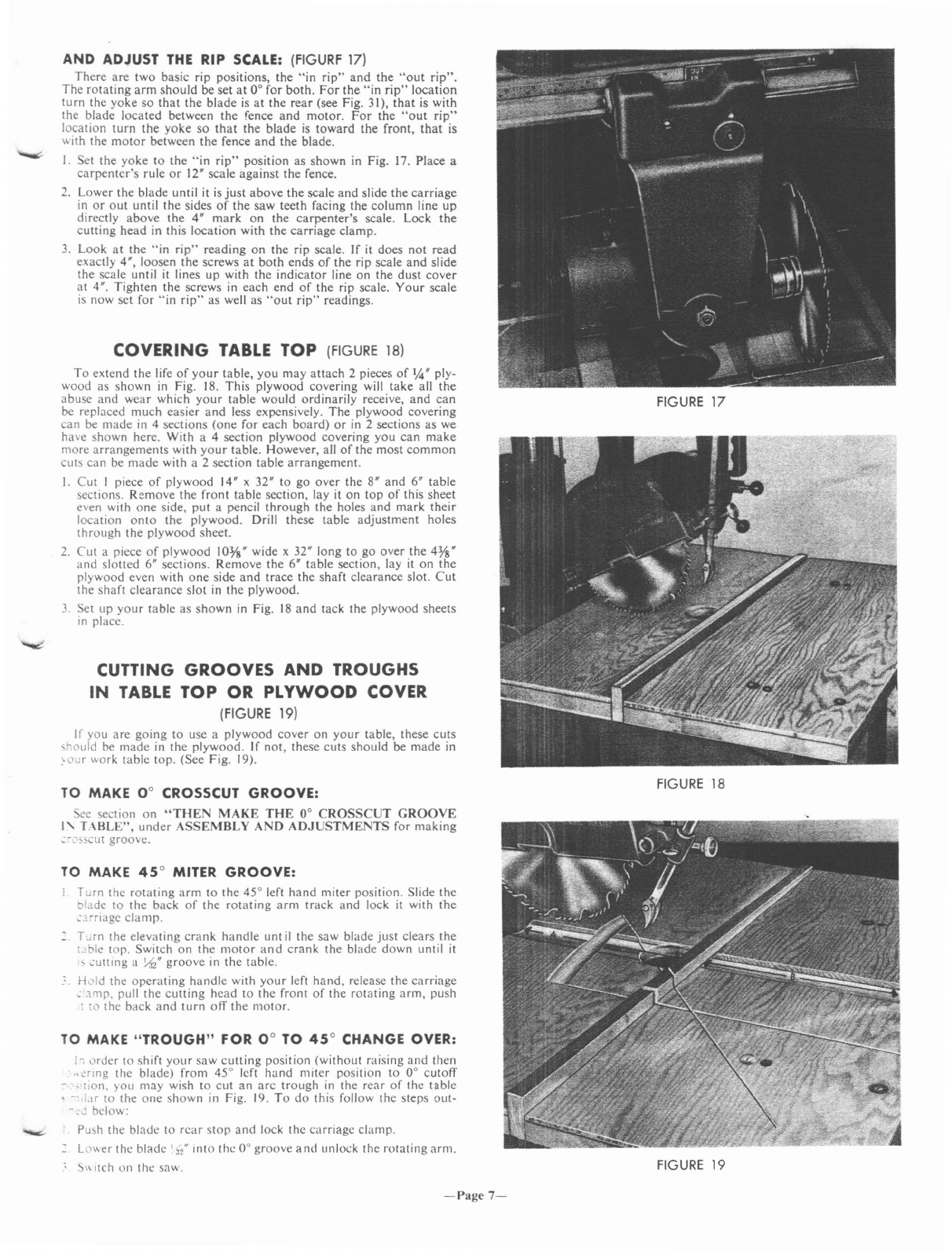
AND ADJUST
THE
RIP
SCALE:
(FIGURF 17)
There
are
two
basic
rip
positions,
the
"in
rip"
and
the
"out
rip".
The
rotating
arm
should
be
set
at
0°
for
both.
For
the
"in
rip"
location
turn
the
yoke
so
that
the
blade
is
at
the
rear
(see
Fig.
31),
that
is
with
the
blade
located
between
the
fence
and
motor.
For
the
"out
rip"
location
turn
the
yoke
so
that
the
blade
is
toward
the
front,
that
is
with
the
motor
between
the
fence
and
the
blade.
1.
Set
the
yoke
to
the
"in
rip"
position
as
shown
in
Fig.
17.
Place
a
carpentcr's
rule
or
12'
scale
against
the
fence.
2.
Lower
the
blade
until
it
is
just
above
the
scale
and
slide
the
carriage
in
or
out
until
the
sides
of
the
saw
teeth
facing
the
column
line
up
directly
above
the
4'
mark
on
the
carpenter's
scale.
Lock
the
cutting
head
in
this
location
with
the
carriage
clamp.
3.
Look
at
the
"in
rip"
reading
on
the
rip
scale.
If
it
does
not
read
exactly
4',
loosen
the
screws
at
both
ends
of
the
rip
scale
and
slide
the
scale
until
it lines
up
with
the
indicator
line
on
the
dust
cover
at
4".
Tighten
the
screws
in
each
end
of
the
rip
scale.
Your
scale
is
now
set
for
"in
rip"
as
well as
"out
rip"
readings.
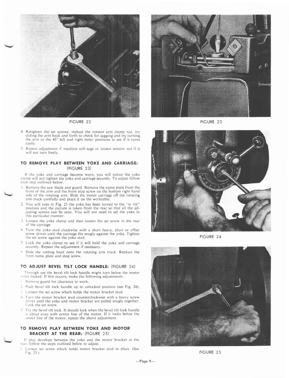
COVERING
TABLE
TOP (FIGURE 18)
To
extend
the
life
of
your
table,
you
may
attach
2pieces
of
1,4'
ply-
wood
as
shown
in Fig.
18.
This
plywood
covering
will
take
all
the
abuse
and
wear
which
your
table
would
ordinarily
receive,
and
can
be
replaced
much
easier
and
less
expensively.
The
plywood
covering
can
be
made
in 4
sections
(one
for
each
board)
or
in 2
sections
as
we
have
shown
here.
With
a 4
section
plywood
covering
you
can
make
more
arrangements
with
your
table.
However,
all
of
the
most
common
cuts
can
be
made
with
a2
section
table
arrangement.
1.
Cut
I
piece
of
plywood
14" x32"
to
go
over
the
8"
and
6"
table
sections.
Remove
the
front
table
section,
lay
it
on
top
of
this
sheet
even with
one
side,
put
apencil
through
the
holes
and
mark
their
location
onto
the
plywood.
Drill
these
table
adjustment
holes
through
the
plywood
sheet.
2.
Cut
a
piece
of
plywood
I0Ys'
wide
x
32"
long
to
go
over
the
4Ys'
and
slotted
6"
sections.
Remove
the
6'
table
section,
lay it
on
the
plywood
even
with
one
side
and
trace
the
shaft
clearance
slot.
Cut
the
shaft
clearance
slot
in
the
plywood.
3.
Set
up
your
table
as
shown
in Fig.
18
and
tack
the
plywood
sheets
in place.
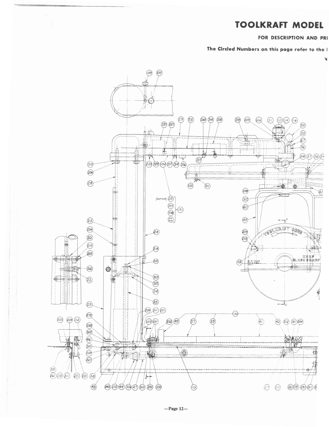
CUTTING GROOVES AND TROUGHS
IN
TABLE
TOP OR PLYWOOD COVER
(FIGURE 19)
If
you
are
going
to
use
a
plywood
cover
on
your
table,
these
cuts
sMuld
be
made
in
the
plywood.
If
not,
these
cuts
should
be
made
in
\
0ur
work
table
top.
(See
Fig.
19).
TO MAKE
0°
CROSSCUT
GROOVE:
S<:e
section
on
"THEN
MAKE
THE
0°
CROSSCUT
GROOVE
I'
T.
.\BLE",
under
ASSEMBLY
A D
ADJUSTMENTS
for
making
:-
.'>scut
groove.
TO
MAKE
45°
MITER
GROOVE:
Turn
the
rotating
arm
to
the
45° left
hand
miter
position.
Slide
the
~Iade
to
the
back
of
the
rotating
arm
track
and
lock
it with
the
:."riage
clamp.
- T.lrn
the
clevating
crank
handle
unt
il
the
saw
blade
just
clears
the
,,,ble
lOp.
Switch
on
the
motor
and
crank
the
blade
down
until it
"..:uttlllg a
;,{z"
groove
in
the
table
.
..
Hvld
the
operating
handle
with
your
left
hand,
release
the
carriage
;
~rnp.
pull
the
cutting
head
to
the
front
of
the
rotating
arm,
push
:
:0
the
back
and
turn
off
the
motor.
TO MAKE
"TROUGH"
FOR
0°
TO
45°
CHANGE OVER:
I-
vrder
lO
shift
your
saw
cutting
position
(without
raising
and
then
.'~r1ng
the
blade)
from
45°
Icft
hand
miter
position
to
0°
cutoff
• -
lion.
you
may
wish
to
cut
an
arc
trough
in
the
rear
of
the
table
,
..
I,lr
to
the
one
shown
in Fig. 19.
To
do
this
follow
the
steps
out-
-d
below:
Push
the
blade
to
rcar
stop
and
lock
thc
carriage
clamp.
-
Lo"er
the
blade
'{/
into
the
0°
groove
a
nd
unlock
the
rotating
arm.
S"
itch
on
the
saw.
FIGURE
17
FIGURE
18
FIGURE
19
-Page
7-

FIGURE
20
FIGURE
21
4. Lift
the
rotating
arm
index
pin
and
swing
the
blade
to
the
right
slowly
until
the
rotating
arm
index
pin
automatically
locates
the
45°
miter
position.
5.
Shift
the
saw
back
to
the
0°
groove,
lower
the
blade
another
~'<2H
and
repeat
the
operation.
TO MAKE
"TROUGH"
FOR
RIPPING:
I.
The
rotating
arm
should
be
in
the
0°
cutoff
position
and
the
yoke
in
the
"in
rip"
position.
See
Fig. 19,
Section
A.
2.
Place
the
fence
in
back
behind
all
table
sections
and
lock
it
in
place.
3.
The
blade
should
be
even
with
the
inside
edge
of
the
fence
and
the
carriage
clamp
locked.
4.
Start
the
motor
and
lower
the
blade
until
it
is
cutting
aI
:r/
deep
trough
into
the
table.
5.
Hold
the
operating
handle
with
your
left
hand.
release
the
carriage
clamp
with
your
right.
pull
the
blade
to
the
front
stop
on
the
roo
tating
arm.
push
it
back
to
the
fence
and
lock
carriage
clamp.
Lower
the
blade
another
'~12'.
release
carriage
clamp
and
pull
the
blade
to
the
front
stop,
push
it
back
and
switch
motor
off.
O.
Raise
the
blade
even
with
the
table
lOp.
Turn
the
yoke
to
the
"out
rip"
position
and
continue
the
rip
trough
cut
to
the
front
of
the
table
following
the
s'!me
procedure
as
used
to
make
the
"in
rip"
trough.
See
Section
Bin Fig. 19.
ADJUSTMENTS
TO
COMPENSATE
FOR
WEAR
TO ADJUST
THE
CLUTCH
ASSEMBLY: (FIGURE 20)
In
order
to
safeguard
the
motor
and
belt
of
your
machine,
we
have
equipped
it
with
a
specially
designed
clutch
assembly.
This
clutch
has
been
set
at
the
factory
at
the
proper
tension
to
assure
correct
cutting
performance.
Continuous
overloading
or
intermittent
overloading
over
a
long
period
of
time
may
cause
wear
to
the
slip
clutch
parts
and
make
it
slip
too
readily.
To
reset
the
clutch
make
the
following
adjustments:
1.
Remove
the
saw
guard,
the
saw
blade,
the
arbor
bracket
and
the
belt.
(See
Fig.
20).
2.
Remove
the
cotter
pin,
hold
the
motor
shaft
with
a
screw
driver,
(this
shaft
is
crossdrilled
with
4
locating
holes),
turn
the
nut
clock-
wise
1/12
revolution
and
insert
the
cotter
pin
through
the
shaft
hole
which
is
:ocated
90°
from
the
hole
from
which
you
removed
the
pin.
Spread
the
ends
of
the
pin
so
it will
not
slip
out.
3.
Slip
the
belt
over
the
large
pulley
carefully
so
that
the
teeth
on
the
belt
are
engaged
with
those
on
the
pulley.
Slip
the
small
pulley
and
arbor
bracket
into
position.
Be
sure
that
the
teeth
of
the
small
pulley
are
engaged
with
those
on
the
belt.
4.
You
will
notice
that
there
are
4
oversize
clearance
holes
for
mount-
ing
the
arbor
bracket
to
the
motor
bracket.
These
holes
are
for
adjusting
the
arbor
bracket
to
the
proper
location
to
maintain
belt
tension.
Insert
the
4
fastening
serews
through
the
arbor
bracket
into
the
motor
bracket
and
tighten
them
by
hand.
Press
down
gently
with
one
hand
on
the
arbor
bracket,
hold
it in
this
position
to
maintain
a
slight
belt
tension
and
tighten
the
4
screws
securely.
CAUTION:
Do not force the arbor bracket down, gentle pressure
from your hand
will
hold the belt
at
the proper tension.
5.
Mount
the
blade
and
guard
and
try
a
sample
cut.
If
the
blade
still
slips
too
readily,
repeat
the
above
adjustment
until
the
blade
slips
only
when
overloaded.
IF
CLUTCH
DOES
NOT
SLIP:
If
your
saw
blade
will
not
slip
under
extreme
overload
or
abuse,
it
has
probably
become
clogged
with
sawdust
or
other
foreign
material
and
needs
to
be
cleaned.
1.
Before
removing
the
clutch
assembly.
scratch
a
mark
on
one
of
the
corners
of
the
castle
nut
and
another
mark
directly
in line
with
it
on
the
outer
bronze
washer.
2.
Remove
the
cotter
pin
and
castle
nut
and
slip
the
clutch
assembly
off
the
shaft.
Slip
the
Woodruff
Key
out
of
the
slot
in
the
motor
shaft.
3.
Clean
all
the
parts
thoroughly
in
kerosene.
Let
the
bronze
washers
soak
overnight
in a
pan
of
S.A.E.
No.
JO
Oil.
TO
REASSEMBLE
THE
CLUTCH:
1.
Slip
the
Woodruff
Key
into
the
slot
on
the
motor
shaft
and
slide
the
inner
bronze
washer
onto
the
shaft
against
the
spacer
sleeve.
2.
Place
asteel
washer
on
each
side
of
the
pulley
\\ ith
the
pins
extend-
ing
into
anyone
of
the
4
slots
around
the
pulley. Slip the
outer
bronze
washer
into
the
flange
side
of
the
pulley".
3.
Slide
the
above
four
parts
onto
the
motor
shaft
and
over
the
inner
bronze
washer.
Place
the
spring
"asher
on
the
motor
shaft
against
the
outer
bronze
washer
and
turn
the
castle
nut
onto
the
motor
shaft
by
hand.
Hold
the
shaft
with
a
scre\\
dri\
er
and
tighten
the
castle
nut
with
a
wrench
until
the
mark
on
the
nut
lines
up
with
the
one
on
the
outer
bronze
washer.
Insert
the
cotter
pin,
reassemble
the
drive
and
make
a
test
cut.
TO REMOVE
THE
PLAY BETWEEN
THE
UPPER
ARM
AND
ROTATING ARM: (FIGURES
21
and
22)
If
the
rotating
arm
sags
"hen
the
cutting
head
is
mo\ed
to
the
ends
of
the
arm,
the
arm
pi\
at
stud
connecting
the
upper
and
lower
arms
should
be
adjusted
to
take
up
the
"ear.
To
adjust
folio"
each
step
as
outlined
below:
I.
See
Figure
21.
Remo\e
the
rotate>r
arm
clamp
nut
and
loosen
the
screws
on
either
side
of
the
bo~
on
the
front
of
the
upper
arm.
2.
Loosen
the
set
sere\\
in
the
inner
te
Slon
r.
t
just
enough
so
that
the
tension
nut
will
not
be
laded
In
pla-.:e
l'f1
te
threads
of
the
stud.
See
Figure
21.
3.
See
Figure
22.
Hold
the
arm
pi\ot
5!UJ
\
",;
"large S,'re"
driver
to
keep
it
from
turning
and
tighten
t e
Jnner
tenslI:,n
nut
by turn1l1g
it
clockwise
with
a
"I~'
open
enC
"re,.:;;
1.;;<
Arbor
l'ut
Wrench
XM-2158
for
this
adjustment
If
\0"
ra\
,wr'hased
it
as
one
of
your
Radial
Arm
Sa\\
H,Xl'SSOf!C"> I,
-Page
8-
FIGURE
22
4.
Retighten
the
set screws, replace
the
rotator
arm
clamp
nut,
try
sliding the
arm
back
and
forth
to
check for sagging
and
try
turning
the
ann
to
the 45° left
and
right
miter
positions to see if it
turns
easily.
5.
Repeat
adjustment
if
machine
still sags
or
loosen tension
nut
if it
will
not
turn
freely.
TO REMOVE PLAY BETWEEN YOKE
AND
CARRIAGE:
(FIGURE 23)
If the
yoke
and
carriage
become
worn,
you will notice the
yoke
clamp
will not tighten the
yoke
and
carriage
securely.
To
adjust
follow
each step
outlined
below.
I.
Remove
the
saw
blade
and
guard.
Remove
the
name
plate
from
the
front
of
the
arm
and
the
front
stop
screw
on
the
bottom
right
hand
side
of
the
rotating
arm.
Slide the
motor
carriage
off
the
rotating
arm
track
carefully
and
place it
on
the
worktable.
2.
You
will
note
in
Fig.
23
the
yoke
has
been
turned
to
the
"in
rip"
position
and
the
picture
is
taken
from
the
rear
so
that
all
the
ad-
justing
screws
can
be seen.
You
will not need
to
set the
yoke
in
this
particular
manner.
3.
Loosen the
yoke
clamp
and
then
loosen the set screw
in
the
rear
of
the
carriage.
~.
Turn
the
yoke
stud
clockwise with a
short
heavy, plain
or
offset
screw
driver
until
the
carriage
fits
snugly
against
the
yoke.
Tighten
the set screw
against
the
yoke
stud.
<Lock the
yoke
clamp
to
see if it will hold the
yoke
and
carriage
securely.
Repeat
the
adjustment
if necessary.
f..
Slide the
cutting
head
onto
the
rotating
arm
track.
Replace
the
front
name
plate and,
stop
screw.
TO ADJUST
BEVEL
TILT LOCK HANDLE: (FIGURE 24)
Through
use
the
bevel tilt lock
handle
might
turn
below
the
motor
A
-en
locked. If this
occurs,
make
the following
adjustments.
Remove
guard
for
clearance
to
work.
Push bevel tilt lock
handle
up
to
unlocked
position (see Fig. 24).
Loosen the
set
screw
which
holds
the
motor
bracket
stud
.
.:
Turn
the mOlOr
bracket
stud
counterclockwise
with aheavy screw
Jmcr
until
the
yoke
and
motor
bracket
are
pulled snugly
together.
Lcx:k
the set screw.
Try the bevel tilt lock.
It
should
lock when
the
bevel tilt lock
handle
,s
about
even with
center
line
of
the
motor.
If
it
locks below
the
,enter
line
of
the
motor,
repeat
the
above
adjustment.
TO REMOVE PLAY BETWEEN YOKE
AND
MOTOR
BRACKET AT
THE
REAR: (FIGURE 25)
If
play
develops
between
the
yoke
and
the
motor
bracket
at
the
rear, follow the
steps
outlined
below
to
adjust.
ILoosen set screw which
holds
motor
bracket
stud
in
place. (See
Fig. 25.)
FIGURE
23
FIGURE
24
FIGURE
25
-Page
9-

FIGURE
26
FIGURE
27
FIGURE
28
2.
Hold
the
motor
bracket
stud
with
a
heavy
screw
driver
and
turn
the
nut
clockwise
with
a
wrench
until
the
motor
bracket
and
yoke
fit
snugly
but
not
tight
against
each
other.
3.
Release
bevel
tilt
lock
and
try
tilting
the
motor
several
times.
If
further
adjustment
is
necessary
repeat
the
above
instructions.
Turn
nut
counterclockwise
to
loosen.
TO
REMOVE PLAY
FROM
PEDESTAL: (FIGURE 26)
To
remove
any
play
which
may
develop
between
the
pedestal
and
the
column
follow
the
steps
outlined
below.
I.
If
the
column
is
loose
in
the
pedestal;
loosen
the
locking
bolt.
turn
the
adjusting
screw
sleeve
about
1/12
revolution
counterclockwise,
(see
Fig.
26),
hold
it in
position
with
one
wrench
and
lock
it
in
this
position
by
turning
the
locking
bolt
clockwise
with
another
wrench.
CAUTION:
Never
turn
the
adjusting
sleeve all
the
way into
the
pedestal
in a
clockwise
direction.
This
could
cause
the
pedestal
to
spring
out
of
shape
or
crack.
You
probably
will
never
have
to
turn
the
adjusting
sleeve in
or
out
more
than
'/.s
of
a
revolution
to
adjust.
2.
Try
raising
and
lowering
the
blade
with
the
elevating
crank
handle.
If
it is
too
loose
repeat
above
adjustment.
If
it
is
too
tight,
loosen
the
locking
bolt,
turn
the
adjusting
sleeve in a
clockwise
direction
and
retighten
the
locking
bolt.
Try
raising
and
lowering
the
blade
again
and
make
any
further
adjustment
that
is
necessary.
TO REMOVE SIDE PLAY
FROM
THE
UPPER ARM:
(FIGURE
27)
After
your
saw
has
been
in use
for
some
time
you
may
notice
that
the
arm
(even
though
locked
in
position)
can
be
shifted
from side
to
side
when
the
blade
is
at
the
front
end
of
the
rotating
arm.
Follow
the
steps
outlined
below
to
correct
this
condition.
I.
On
each
side
of
the
pedestal
at
the
back
you
will
note
2
headless
set
screws
with
check
nuts.
(See
Fig. 27).
You
must
take
up
the
wear
evenly
on
both
sides
of
the
pedestal
by
adjusting
the
brass
gibs
from
each
side.
First,
hold
the
screws
on
the
right
side
with
a
screw
driver
and
loosen
the
check
nuts.
2.
Now
tighten
the
screws
securely
and
count
the
number
of
clock-
wise
turns,
then
back
the
two
screws
out
exactly
'/2
the
number
of
turns
it
took
to
tighten
them.
Hold
each
screw
in this
location
with
a
screw
driver
and
tighten
the
check
nut.
3.
Next,
loosen
the
upper
and
lower
check
nuts
on
the
left
side
with a
wrench
and
tighten
the
set
screws.
Lock
them
securely
in
position
with
the
check
nuts.
4.
Try
the
arm
to
see
if
the
side
motion
has
been
eliminated.
Try
to
raise
the
blade
with
the
elevating
crank
handle.
Repeat
the
adjust-
ment
if
all
side
play
is
not
eliminated.
If
the
gib
pressure
is
too
great
on
the
column
key
and
causes
a
bind
"hen
raising
or
lowering
the
cutting
head,
back
off
the
set
screws
slightly
on
one
side
until
the
bind
is
eliminated
and
lock
check
nuts.
5.
This
adjustment
might
have
disturbed
the
setting
of
the
rotating
arm.
Check
as
described
under
THE1'\
SQLJARE
BLADE
CROSS-
CUT
TRAVEL
and
make
any
necessary
adjlolstments.
TO ADJUST
THE
CARRIAGE
BALL
BEARINGS:
(FIGURE
28)
The
carriage
is
mounted
on
the
rotating
arm
track
with 4ball
bear-
ings
and
2
roller
bearings.
Two
ball
bearings
are
mounted
in afixed
position
on
each
side
of
the
carriage
and
roll
along
the
45°
track.
Two
roller
bearings
are
mounted
in afixed
position
on
the
bOllom
of
the
rotating
arm.
The
two
bearings
on
the
left side
are
permanent,
but
the
two
ball
bearings
mounted
on
the
right
hand
SIde
of
the
track
are
adjustable.
If
play
develops
bet"een
the
track
and
the
bearings.
follow
the
steps
outlined
below
to
adjust.
I.
(See Fig. 28.)
Remove
the
carriage
damr
knob.
2.
Remove
the
right
hand
dust
cover
b\
taking
(\ut
the
two screws.
J.
Loosen
the
set
sere'"
on
the
carriage
SIde
rlate
b~
turning
It
counter-
clockwise
<l
few
turns.
4.
Tighten
the
front
hex
bolt
and
the
rear
he'
boll
aprroxill1ately
the
same
number
of
turns
to
move
the
Sltle
rlate
In
e\enly.
Keep
trying
the
travel
on
the
track
as
~()U
3J)U>t
l<'
mdke
surc
the
bearings
aren't
binding
on
the
track.
5.
After
you
have
the
he>.
bolts
tlghlen"J
>t' th,l
the
carriage
moves
smoothly
and
some"
hat
snuglY al(\ng
the
track.
tIghten the
socket
set
scrcw
securel~
.
-Page
10-

RIGHT HAND MITERING
FIGURE
30
FIGURE
29
FIGURE
31
CROSSCUTIING
RIPPING
7
0.
It
is
important that the bearings be
in
line from front to back on
the track ·arm.
To
check this, apply some light grease to the tracks
of
the rotating arm. Wipe the grease down to athin film. Then pull
the carriage to the front stop
of
the track and push it back to observe
the tracks left
in
the grease. There should be only one mark, the
width
of
the bearing face. If the bearings are
not
moving in the
same line, you must make further adjustments. If the front bearings
are higher than the rear, tighten the rear hex screw. If the front
bearing
is
lower, you' must tighten the front hex bolt. This adjust-
ment
is
important
in
keeping your saw
SQuare
for ripping operations.
The
felt
track wipers on each side
of
the right
and
left hand dust
covers
will
wear and should be adjusted occasionally so
that
sawdust
won't pile up on the track
and
cause abind
in
the crosscut travel.
I.
Loosen the screws
in
the metal backing plates.
2.
Slide each felt wiper down until it fits snugly against the track
and
tighten the screws.
TO
ADJUST
FELT
TRACK
WIPERS:
OPERATIONS
CROSSCUTTING:
(FIGURE
29)
The rotating
arm
must be positioned
at
0° on the miter scale.
The
motor position should read 0° on the bevel tilt scale and the yoke
should be positioned to the left
of
the rotating arm
in
the cutoff po-
sition. Place the wood on the work table against the fence.
The
blade
should be behind the fence and should be lowered into the crosscut
groove
in
the table. Make sure all clamps except the carriage clamp
are
in
the lock position. Hold the operating handle with one hand
and turn the saw on with the other. Hold the work against the fence,
pull the blade through the work, push the blade back to the rear
of
the fence and turn saw off. (See Fig. 29.)
For
best crosscut results, use IO-CC-58 Crosscut Blade with the
Model 910A Radial
Arm
Saw. See
ACCESSORIES
section under
BLADES for prices.
RIGHT
AND
LEFT
HAND
MITERING:
(FIGURE
30)
(See Fig. 20.)
The
rotating
arm
should be positioned to
your
desired
miter angle as indicated on the miter scale.
The
most common miter
cuts are 45° right hand
and
45° left hand.
The
miter index pin will
locate these positions automatically. Push the blade to the rear
of
the
fence and lower it into the 45° miter groove. Hold the work against
the fence, pull the blade through the work and push the blade back.
For best results use the same blade as for crosscutting.
Radial Arm Saws
do
not
require frequent oiling. Oil merely tends
.0
collect dust and clog up the mechanism. Oil the 3index pins
and
moving surfaces
about
once per month with S.A.E. No. 20 Oil to
minimize the wear. Squirt a
few
drops through the slot
in
the rear
of
the pedestal on the thrust bearing
and
on the elevating screw
about
once per month. Never oil the Rotating Arm Track. This track should
be cleaned occasionally with lacquer thinner
or
carbon
tetrachloride
to remove any dirt
or
grease.
LUBRICATION
RIPPING:
(FIGURE
31)
Your machine
will
rip to the center
of
a581
11."
wide board. You can
rip boards up to
18"
wide with the saw in the
"in
rip"
position
and
boards from
12"
to 29" wide with the saw
in
the
"out
rip"
position.
To set the machine to the
"in
rip"
position, (see Fig. 31), turn the
rotating arm to 0° position, turn the yoke to
your
left until it auto-
matically indexes
in
the position with the blade parallel to the fence,
between the fence and the motor. When using the
"in
rip"
position,
lock the carriage on the rotating
arm
track
at
the desired width
of
the board to be ripped. Lower the blade into the rip trough, feed the
material through from the right hand side as shown
in
Fig. 31. Never
rip from the anti-kickback side
of
the guard. Always tilt the guard so
that the ripping end just clears the work, lower the anti-kickback arm
until the grips hang
Ys"
below the work. Never rip without using the
guard and anti-kickback grips.
To Set the Machine to the
"Out
Rip"
Position, turn the yoklt to
your right until
it
indexes parallel to the fence with the motor between
the fence and the blade.
The
"out
rip"
cutting operation
is
performed
In
the same
manner
as the
"in
rip"
but since cutting head
is
turned
180°
the work
is
fed
from the left instead
of
from the right.
The
"out
rip"
position
is
normally used only for ripping wider than
18",
Long
work should
be
supported, as it comes through the blade and over the
opposite end
of
the table to prevent it from kicking up into the blade.
-Page
11-
I
@ /
@@J@
"\
:1:
I/
-jtf-
\~~
",
--
r(/
',A'
,
,
/
-Page
12-
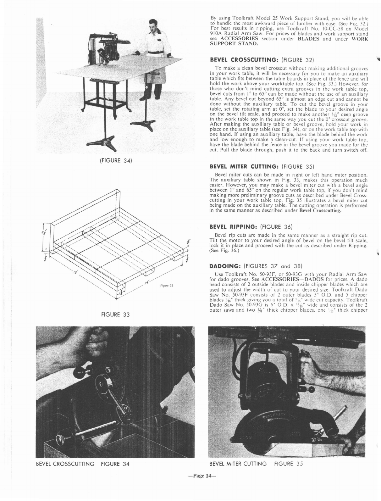
TOOLKRAFT MODEL
FOR DESCRIPTION
AND
PRI
The
Circled
Numbers
on
this
page
refer
to
the
I
<;:.:-::::-,
..
~~~
i
\~b£i<~Ii:$cli~~I}l\
•
I..
..'
J
(I
__
----I
..!.
_
'}----"'-~--\
~
@§@~
I
,!
,-----~
-H+-iH-'--Y-'
~
---.-tt
-
----..
---------------
-----~~_.
--
----
--------~---~~-~~
//3

ARADIAL ARM
SAW
F
PARTS
SEE
THE
PARTS
LIST
rs
in
the
Index
Number
Column
of
the
Parts
List.
~
._--
:':.---®
-'-
j-
/3
7
/3
.32
-Page
13-
~
/

TOOLKRAFT MODEL
910A
RADIAL ARM
SAW
FOR DESCRIPTION AND PRICES OF
PARTS
SEE
THE
PARTS
LIST
The
Circled
Numbers
on
this
page
refer
to
the
Nu_mb~rs
In
the
Index
Number
Column
of
the
Parts
List.
3
-5
~
__
"'....L _
c
3
2.
~
-++~--H"-d).----r1P=-===-~~~
'.
L
-I
By
using
Toolkraft
Model
25
Work
Support
Stand,
you
will be
able
to
handle
the most
awkward
piece
of
lumber
with easc. (Sec Fig. 32.)
For
best results
in
ripping,
usc
Toolkraft
No.
IO-CC-58 on Model
910A
Radial
Arm
Saw.
For
prices
of
blades
and
work
support
stand
see
ACCESSORIES
section
under
BLADES
and
under
WORK
SUPPORT
STAND.
BEVEL
CROSSCUTTING:
(FIGURE
32)
To
make
aclean bevel
crosscut
without
making
additional
grooves
in
your
work
table,
it
will be necessary for
you
to
make
an
auxiliary
table
which fits between
the
table
boards
in
place
of
the fence
and
will
hold
the
work
above
your
worktable
top. (See Fig. 33.) However, for
those
who
don't
mind
cutting
extra
grooves
in
the
work
table
top,
bevel
cuts
from
I°
to
65°
can
be
made
without
the
use
of
an
auxiliary
table.
Any
bevel
cut
beyond
65°
is
almost
an
edge
cut
and
cannot
be
done
without
the
auxiliary
table.
To
cut
the bevel
groove
in
your
table,
set
the
rotating
arm
at
0°, set
the
blade
to
your
desired angle
on
the
bevel tilt scale,
and
proceed
to
make
another
~{2'
deep
groove
in
the
work
table
top
in
the
same
way
you
cut
the 0°
crosscut
groove.
After
making
the
auxiliary
table
or
bevel
groove,
hold
your
work
in
place
on
the
auxiliary
table
(see Fig. 34),
or
on
the work table
top
with
one
hand.
If
using
an
auxiliary
table, have
the
blade
behind
the
work
and
low
enough
to
make
a
clean-cut.
If
using
your
work
table
top,
have
the
blade
behind
the
fence in
the
bevel
groO\e
you
made
for
the
cut.
Pull
the
blade
through,
push
it
to
the
back
and
turn
switch off.
(FIGURE
34)
FIGURE
33
BEVEL
CROSSCUTTING
FIGURE
34
BEVEL
MITER CUTTING:
(FIGURE
35)
Bevel
miter
cuts
can
be
made
in
right
or
left
hand
miter
position.
The
auxiliary
table
shown
in
Fig. 33,
makes
this
operation
much
easier. However,
you
may
make
abevel
miter
cut
with abevel
angle
between I°
and
65°
on
the
regular
work
table
top,
if you
don't
mind
making
more
preliminary
groove
cuts
as
described
under
Bevel Cross-
cutting
in
your
work
table
top.
Fig. 35 illustrates abevel
miter
cut
being
made
on
the
auxiliary
table.
The
cutting
operation
is
performed
in
the
same
manner
as
described
under
Bevel Crosscutting.
BEVEL
RIPPING:
(FIGURE
36)
Bevel
rip
cuts
are
made
in
the
same
manner
as a
straight
rip cut.
Tilt
the
motor
to
your
desired
angle
of
bevel
on
the bevel tilt scale,
lock it
in
place
and
proceed
with
the
cut
as
described
under
Ripping.
(See Fig. 36.)
DADOING:
(FIGURES
37
and
38)
Use
Toolkraft
No.
50-93F,
or
50-93G with
your
Radial
Arm
Saw
for
dado
grooves. See
ACCESSORIES-DADOS
for prices. A
dado
head
consists
of
2
outside
blades
and
inside
chipper
blades which
are
used
to
adjust
the
width
of
cut
to
your
desired size.
Toolkraft
Dado
Saw
No.
50-93F
consists
of
2
outer
blades
5'
0.0.
and
5
chipper
blades
~fi'
thick giving
you
atotal
of
"16'
"ide
cut
capacity.
Toolkraft
Dado
Saw
No.
50-93G
is
6'
0.0.
x
1;16'
"ide
and
consists
of
the 2
outer
saws
and
two '/s' thick
chipper
blades.
one
1-(6"
thick
chipper
BEVEL
MITER
CUTTING
FIGURE
35
-Page
14-
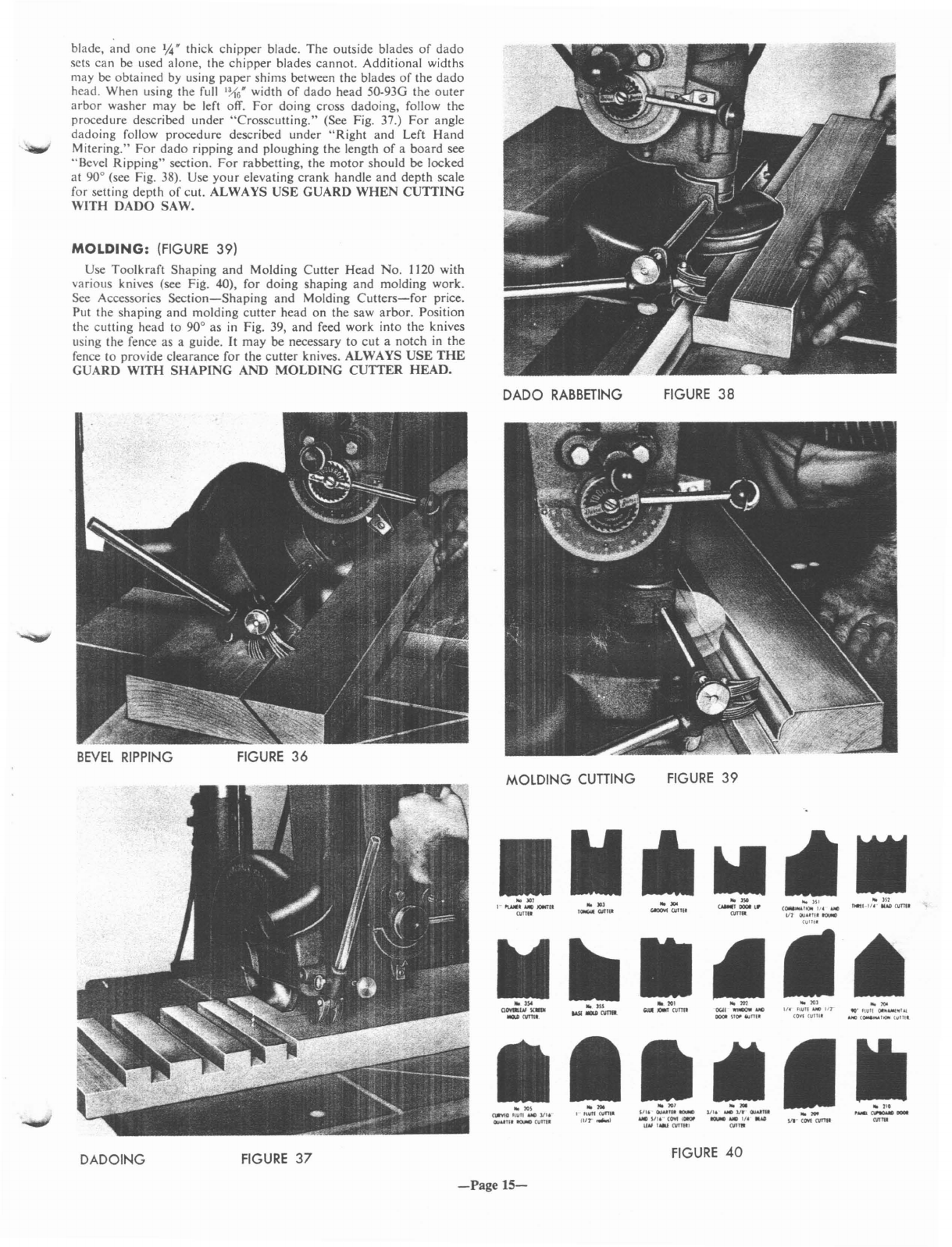
blade, and one
~.
thick chipper blade. The outside blades
of
dado
sets can
be
used alone, the chipper blades cannot. Additional widths
may
be
obtained
by
using paper shims between the blades
of
the dado
head. When using the full
';(6'
width
of
dado head 50-93G the outer
arbor
washer may be left off.
For
doing cross dadoing, follow the
procedure described under "Crosscutting." (See Fig. 37.)
For
angle
dadoing follow procedure described under
"Right
and Left Hand
Mitering."
For
dado ripping and ploughing the length
of
aboard see
"Bevel Ripping" section.
For
rabbetting, the motor should be locked
at 900(see Fig. 38). Use
your
elevating crank handle
and
depth scale
for setting depth
of
cut. ALWAYS USE GUARD
WHEN
CUTTING
WITH
DADO
SAW.
MOLDING:
(FIGURE
39)
Use Toolkraft Shaping
and
Molding Cutter Head No. 1120 with
various knives (see Fig. 40), for doing shaping
and
molding work.
See
Accessories
Section-Shaping
and Molding
Cutters-for
price.
Put the shaping
and
molding cutter head
on
the saw arbor. Position
the cutting head to 900as
in
Fig. 39, and feed work into the knives
using the fence as aguide.
It
may be necessary to cut anotch
in
the
fence to provide clearance for the cutter knives. ALWAYS
USE
THE
GUARD
WITH
SHAPING
AND
MOLDING
CUTTER HEAD.
BEVEL
RIPPING
DADOING
FIGURE
36
FIGURE
37
DADO
RABBETING
MOLDING CUTIING
-Page
15-
FIGURE
38
FIGURE
39
FIGURE
40

PROFILES
AVAILABLE
AS
EITHER
SHAPER
CUTTERS
OR
MOLDING
KNIVES.
HII"
'AIm
lIAISING
PROFILES
AVAILABLE
ONLY
AS
MOLDING
KNIVES
)r)
"
.'
~I"[J
L_..:DOO.;,;;;,;R
";;:.Ol:::;OI;;;:NG.:;;lm;:...1
_1....-...;DOO=R.:;;;
..
O;:.:LO;;,;;ING;.::(~:.....-~_--=..:..::-:.:~_~_.;.;.:.:.;;;;..;..;.:.=~-';-_~~;.;.;..._-'-_.....;.;,I/.;..."...;fl.;..UT.;..I·'_1.:'
III"
IfAO
PROFILES
AVAILABLE
ONLY
AS
SHAPER
CUTTERS,
Hes.
fINAll
SASH
"ALI
SASH
1·111"
JOINTER
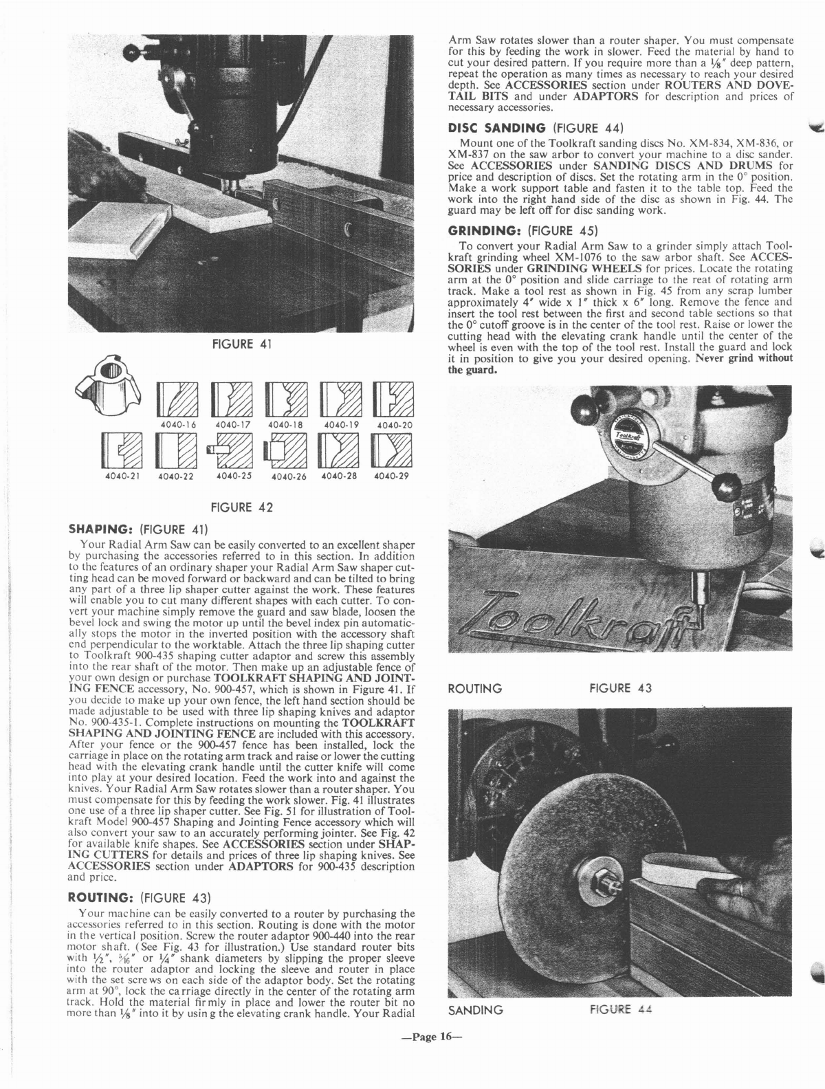
FIGURE
41
~~mrnrnm
4040·
16
4040·17 4040·18 4040-19 4040-20
mrn~~mrn
FIGURE
.!.t,
FIGURE
43
SANDING
Arm
Saw rotates slower than arouter shaper. You must compensate
for this by feeding the work
in
slower. Feed the material
by
hand to
cut
your
desired pattern.
If
you require more than a
l/S"
deep pattern,
repeat the operation as many times as necessary to reach your desired
depth. See
ACCESSORIES
section under
ROUTERS
AND DOVE-
TAIL BITS and under
ADAPTORS
for description and prices
of
necessary accessories.
DISC
SANDING
(FIGURE
44)
'Co
Mount
one
of
the Toolkraft sanding discs No. XM-834, XM-836,
or
XM-837 on the saw
arbor
to convert
your
machine to adisc sander.
See
ACCESSORIES
under
SANDING
DISCS
AND
DRUMS
for
price
and
description
of
discs. Set the rotating
arm
in
the 0° position.
Make awork
support
table
and
fasten
it
to the table top. Feed the
work into the right hand side
of
the disc as shown
in
Fig. 44.
The
guard may be left off for disc sanding work.
GRINDING:
(FIGURE
45)
To
convert
your
Radial
Arm
Saw to agrinder simply attach Tool-
kraft grinding wheel XM-1076 to the saw
arbor
shaft. See ACCES-
SORIES
under
GRINDING
WHEELS
for prices. Locate the rotating
arm
at
the 0° position
and
slide carriage
to
the reat
of
rotating arm
track. Make atool rest as shown in Fig.
45
from any scrap lumber
approximately 4" wide xI" thick x6" long. Remove the fence and
insert the tool rest between the first and second table sections so that
the 0° cutoff groove
is
in the center
of
the tool rest. Raise
or
lower the
cutting head with the elevating
crank
handle until the center
of
the
wheel
is
even with the
top
of
the tool rest. Install the guard and lock
it in position to give
you
your
desired opening. Neyer grind without
the guard.
ROUTING
4040.26
4040·28
4040-29
4040-25
4040-22
4040·21
FIGURE
42
SHAPING:
(FIGURE
41)
Your
Radial
Arm
Saw
can
be easily converted to
an
excellent
shaper
by purchasing the accessories referred to in this section. In addition
to the features
of
an
ordinary
shaper
your
Radial
Arm
Saw
shaper
cut-
ting head can be moved forward
or
backward
and
can
be tilted to bring
any
part
of
athree lip
shaper
cutter against the work. These features
will enable you to cut many different shapes with each cutter.
To
con-
vert
your
machine simply remove the guard and saw blade, loosen the
bevel lock and swing the
motor
up until the bevel index pin automatic-
ally stops the
motor
in the inverted position with the accessory shaft
end perpendicular to the worktable. Attach the three lip shaping
cutter
to Toolkraft 900-435 shaping cutter
adaptor
and screw this assembly
into the rear shaft
of
the motor. Then make up an adjustable fence
of
your
own design
or
purchase
TOOLKRAFf
SHAPING
AND
JOINT-
ING
FENCE
accessory, No. 900-457, which
is
shown in Figure 41.
If
you decide to make
up
your
own fence, the left hand section should be
made adjustable to be used with three lip shaping knives and
adaptor
No. 900-435-1. Complete instructions
on
mounting the
TOOLKRAFf
SHAPING
AND
JOINTING
FENCE
are included with this accessory.
After
your
fence
or
the 900-457 fence has been installed, lock the
carriage in place on the rotating
arm
track and raise
or
lower thecutting
head with the elevating
crank
handle until the cutter knife will come
into play
at
your
desired location. Feed the work into and against the
knives.
Your
Radial
Arm
Saw rotates slower
than
arouter shapero You
must compensate for this by feeding the work slower. Fig.
41
illustrates
one use
of
athree lip
shaper
cutter. See Fig.
51
for illustration
of
Tool-
kraft Model 900-457 Shaping and Jointing Fence accessory which will
also convert
your
saw to an aceurately performing jointer. See Fig. 42
for available knife shapes. See
ACCESSORIES
section under
SHAP-
ING
CUTTERS
for details
and
prices
of
three lip shaping knives. See
ACCESSORIES
section
under
ADAPTORS
for 900-435 description
and price.
ROUTING:
(FIGURE
43)
Your
machine can be easily converted to arouter by purchasing the
accessories referred to
in
this section. Routing
is
done
with the
motor
in
the
vertical position. Screw the router
adaptor
900-440 into the
rear
motor shaft. (See Fig.
43
for illustration.) Use
standard
router bits
with
1;2",
~6"
or
%"
shank
diameters by slipping the proper sleeve
into the router
adaptor
and
locking the sleeve
and
router in place
with the set sere
ws
on each side
of
the
adaptor
body. Set the rotating
arm
at
90°, lock the
ca
rriage directly
in
the center
of
the rotating
arm
track. Hold the material firmly
in
place
and
lower the router bit no
more than
Vs"
into it by usin gthe elevating crank handle.
Your
Radial
-Page
16-

GRINDING
FIGURE
45
SURFACE
SANDING
FIGURE
46
SURFACE
SANDING:
(FIGURE
46)
By
purchasing
Toolkraft
rotary
sander
No.
4004
and
router
adaptor
No. 900-440 you
can
convert
your
machine
for surface
sanding
opera-
tions. (See Fig. 46.)
There
are
two
methods
of
doing
surface
sanding
with
your
Radial
Arm
Saw.
The
most
common
method
would be
to
feed the work
under
the
sander.
Another
method
would be
to
move
the
motor
in
and
out
on
the
rotating
arm
track
while you shift the material
along
the
fence until
the
entire
surface
is
sanded.
For
both
methods
the
motor
should be placed in
the
same
vertical position as for
shaping
and rClwing. Slip the 1;''' insert into the 900-440 adaplClr. insert the
rotary
sander
shank into the sleeve
and
lock
it
securely with the set
s~rews
on
each
side
of
the
adaptor
body. Screw this assembly iuto the
rear
threaded
motor
shaft. Raise
or
lower
the
motor
until
the
sander
is
"64"
below the highest
spot
of
your
material. Always
sand
with the
grain if
it
is
possible. If
you
find it necessary to go deeper
to
clean
up
the material, :ower the
cutting
head
and
repeat the
entire
operation.
Use 50 to 60 grit
sandpaper
for rough stock removal.
When
using
sandpaper
this
coarse
leave
~2"
of
stock for
your
finish
sanding
opera-
tion.
For
finish
sanding
use 120 grit
or
finer
as
required. See
ACCES-
SORIES
section
under
SANDING
for
prices
and
description
of
Tool-
kraft
No.
4004
rotary
sander.
See
ACCESSORIES
under
ADAPTORS
for 900-440 description
and
price.
DRUM
SANDING:
(FIGURE
47)
Toolkraft
No.
4000
and
4001
sanding
drum
sets may be purchased
to convert
your
Radial
Arm
Saw
to
an
excellent tilting
arbor
drum
sander. (See Fig. 47.)
For
details
and
prices
of
No.
4000
and
4001
sanding
drum
sets see
ACCESSORIES
section
under
SANDING
DISCS
AND
DRUMS.
To
convert
your
machine,
turn
the
motor
to
the vertical position. Insert
the
drum
sander
into
the
proper
sleeve
and
adaptor
No.
900-440. Screw this assembly into
the
rear
motor
shaft. Slide the
carriage
over
the
arbor
clearance
cutout
in the table
and use the elevating
crank
handle
to lower
the
drum
into this slot.
As the grit becomes
worn
on
the
sanding
drum,
lower it
further
into
the
arbor
clearance
cutout
to
bring
anew section
of
the
drum
into
play. Use 50
or
60 grit sleeves for rough
sanding
and
120 grit
or
finer
for finishing.
SURFACE
PLANING:
(FIGURE
48)
You
can
easily
convert
your
Radial
Arm
Saw
for use
as
a
surface
planer
by
purchasing
Toolkraft
rotary
surface
planer
No.
4060
and
adaptor
No.
900-440. See
ACCESSORIES
section
under
PLANER
and
ADAPTORS.
To
convert
turn
the
motor
to the vertical position
and
install
rotary
planer
with
adaptor
in
the
same
manner
as
de-
scribed
under
routing
and
surface
sanding. (See Fig. 48.)
You
may
push the
cutter
over
your
material while shifting the material in
along
the fence until the
entire
surface
of
the material
is
planed.
You
may
also lock the
carriage
on
the
rotating
arm
and
feed the material
along
the fence
and
under
the
planer. When you have planed
one
strip off
the material, unlock
the
carriage
clamp,
slide the
cutting
head back
to the edge
of
the first
cut
and
repeat the
operation
until the
entire
surface
is
planed.
The
amount
of
stock which you
can
remove in
one
rass
is
determined by
the
density
of
the material you
are
working
with.
You may plane
up
to l/S" off soft material in
one
pass.
For
hard
wood
adjust the
cutter
up
or
down
as necessary to get full working
capacity
from the
motor
without
overloading
it.
DRUM SANDING
SURFACE
PLANING
FIGURE
47
FIGURE
48
-Page
17-
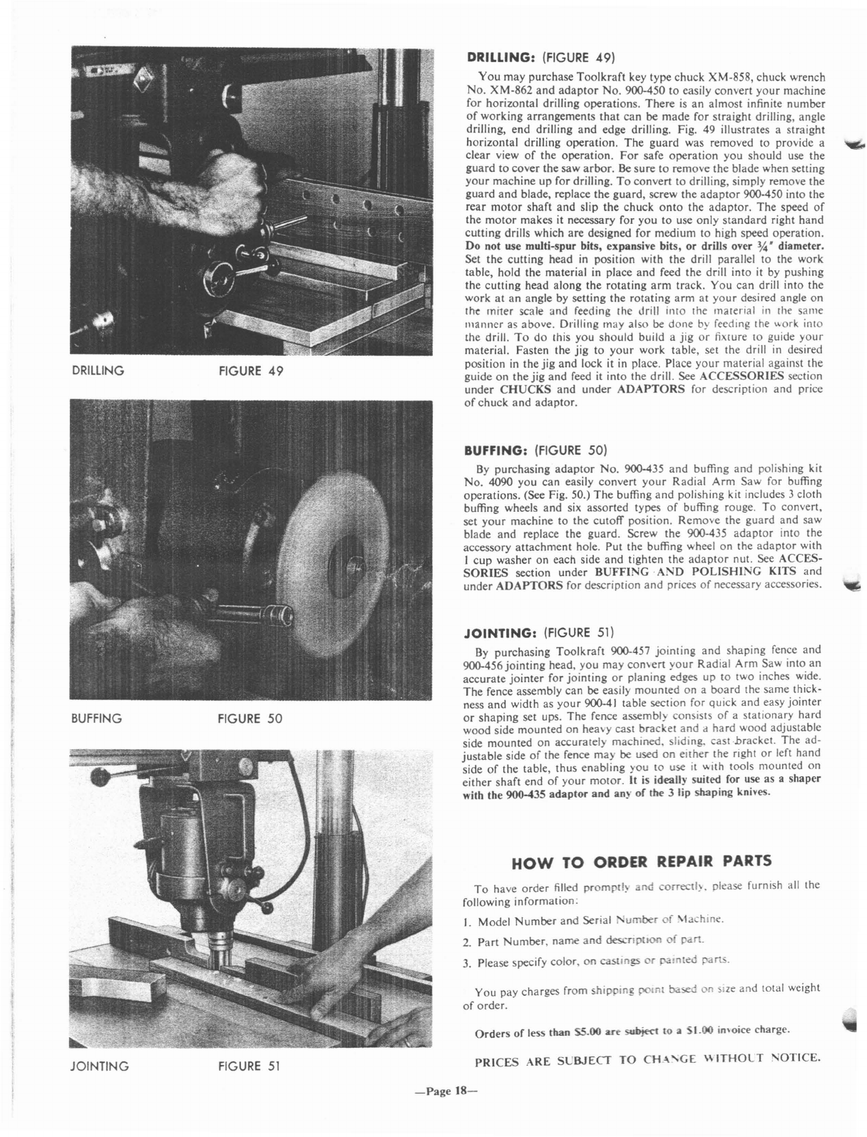
DRILLING
BUFFING
JOINTING
FIGURE
49
FIGURE
50
FIGURE
51
DRILLING:
(FIGURE
49)
You
may purchase
Toolkraft
key type chuck XM-858, chuck wrench
No. XM-862
and
adaptor
No. 900-450
to
easily convert
your
machine
for horizontal drilling operations.
There
is
an
almost infinite number
of
working arrangements
that
can be
made
for straight drilling, angle
drilling, end drilling
and
edge drilling. Fig. 49 illustrates astraight
horizontal drilling operation.
The
guard
was removed to provide a
clear view
of
the operation.
For
safe operation you should use the
guard
to
cover
the saw
arbor.
Be
sure
to
remove the blade when setting
your
machine up for drilling.
To
convert to drilling, simply remove the
guard
and
blade, replace the guard, screw the
adaptor
900-450 into the
rear
motor
shaft
and
slip
the
chuck
onto
the
adaptor.
The
speed
of
the
motor
makes it necessary for you
to
use only
standard
right hand
cutting
drills which are designed for medium to high speed operation.
Do not use multi-spur bits, expansive bits, or drills over
¥.!.
diameter.
Set the cutting head
in
position with the drill parallel to the work
table, hold the material in place
and
feed the drill into it by pushing
the cutting head along the
rotating
arm
track. You can drill into the
work
at
an
angle by setting the
rotating
arm
at
your
desired angle on
th~
miter scale and feeding the drill into the material
in
the same
manner
as above. Drilling
ll10y
also
be
done
by
feeding the work into
the drill.
To
do
this you should build ajig
or
fixlure
10
guide
your
material. Fasten the jig
to
your
work table, set the drill
in
desired
position
in
the
jig
and
lock it in place. Place
your
material against the
guide on the jig
and
feed it into the drill. See
ACCESSORIES
section
under
CHUCKS
and
under
ADAPTORS
for description and price
of
chuck
and
adaptor.
BUFFING:
(FIGURE
50)
By
purchasing
adaptor
No. 900-435
and
buffing
and
polishing kit
No. 4090 you can easily convert
your
Radial Arm Saw for buffing
operations. (See Fig. 50.)
The
buffing
and
polishing kit includes 3cloth
buffing wheels
and
six assorted types
of
buffing rouge.
To
convert,
set
your
machine to the cutoff position. Remove the guard and saw
blade and replace the guard. Screw
the
900-435
adaptor
into the
accessory attachment hole. Put the buffing wheel on the
adaptor
with
I
cup
washer on each side
and
tighten the
adaptor
nut. See ACCES-
SORIES
section under
BUFFING
-
AND
POLISHING
KITS and
under
ADAPTORS
for description
and
prices
of
necessary accessories.
JOINTING:
(FIGURE
51)
By
purchasing Toolkraft 900-457
jointing
and
shaping fence
and
900-456 jointing head, you may convert
your
Radial Arm Saw into an
accurate
jointer
for jointing
or
planing edges up
to
two inches wide.
The
fence assembly can be easily
mounted
on aboard the same thick-
ness
and
width as
your
900-41 table section for quick and easy jointer
or
shaping set ups. The fence assembly consists
of
astationary hard
wood side mounted
on
heavy cast bracket
and
dhard wood adjustable
side mounted on accuratelv machined. sliding. cast-bracket. The ad-
justable side
of
the fence
~ay
be
used
on
eith~r
the right
or
left hand
side
of
the table, thus enabling you
to
use it
"ith
100is mounted
on
either shaft end
of
your
motor.
It
is
ideaU)' suited for use as ashaper
with the 900-435
adaptor
and an)'
of
the 3lip shaping knives.
HOW
TO ORDER REPAIR
PARTS
To
have order filled
promptl~
and
correctl~.
please furnish all the
following information:
I. Model
Number
and Serial
1'umber
of
\Ia
-hine.
2.
Part
Number, name
and
descnplloo
of
part.
3. Please specify color,
on
castings
or
J:"!lnted
parts.
You pay charges from shipping
p0lnl
based
on
Size
and total weight
of
order.
Orders
of
less than
SS.OO
are
su~
to a
SI.OO
in'oice charge.
PRICES
ARE
SL'BJECT
TO
CH
-\
'GE
\\
ITHOL
T
NOTICE.
-Page
18-
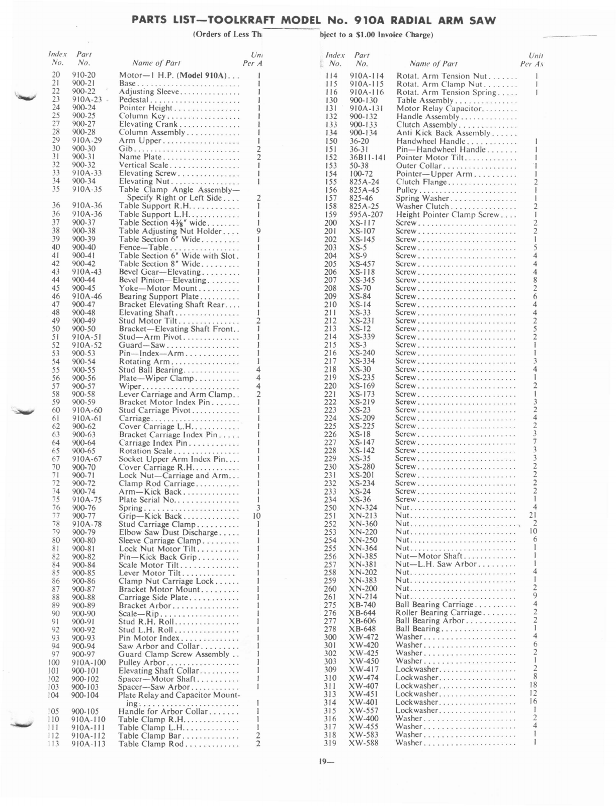
PARTS LIST-TOOLKRAFT
MODEL
No.
910A
RADIAL
ARM
SAW
(Orders
of Less
Th,
bject to a$1.00 Invoice Charge)
\
Index
Part
No. No.
20 910-20
21
900-21
22
900-22
23
910A-23
24 900-24
25 900-25
27
900-27
28
900-28
29
910A-29
30 900-30
31
900-31
32
900-32
33
910A-33
34 900-34
35
910A-35
36
910A-36
36
910A-36
37 900-37
38 900-38
39 900-39
40
900-40
41
900-41
42 900-42
43
910A-43
44 900-44
45 900-45
46
910A-46
47 900-47
48 900-48
49
900-49
50 900-50
51
910A-51
52
910A-52
53
900-53
54 900-54
55
900-55
56 900-56
57 900-57
58
900-58
59 900-59
60
910A-60
61
910A-61
62 900-62
63 900-63
64 900-64
65 900-65
67 910A-67
70 900-70
71
900-71
72 900-72
74 900-74
75
910A-75
76 900-76
i7
900-77
78
910A-78
79
900-79
80 900-80
81
900-81
82 900-82
84 900-84
85
900-85
86 900-86
87 900-87
88
900-88
89 900-89
90 900-90
91
900-91
92 900-92
93 900-93
94 900-94
97 900-97
I
DO
91
OA-I
DO
101
900-101
102
900-102
103
900-103
104
900-104
105
900-105
110
910A-110
III
910A-IJI
112
910A-I/2
113
910A-113
Urn
Nam!!
of
ParI Per A
Motor-I
H.P.
(ModeI910A)...
I
Base. . . 1
Adjusting Sleeve. . . . . . . . . . . . . . . J
Pedestal. . . .
...
.
..
.
.....
..
..
. . I
Pointer Height. . . . . . . . . . . . . . . . I
Column
Key.
................. I
Elevating
Crank.
. . . . . . . . . . . . . . I
Column Assembly. . . . . . . . . . . . . I
Arm
Upper...................
I
Gib.....
2
Name
Plate.
. . . . . . . . . . . . . . . . . . 2
Vertical Scale. . . . . . . . . . . . . . . . . I
Elevating Screw. . . . . . . . . . . . . . . I
Elevating Nut ,
..
.
..
. . I
Table
Clamp
Angle
Assembly-
Specify Right
or
Left Side. ... 2
Table Support
R.H..
. . . . . . . . . . J
Table
Support
L.H.....
.....
. . . I
Table Section
4%"
wide. . . . . . . . 1
Table Adjusting
Nut
Holder. . . . 9
Table Section 6" Wide. . . . . . . . . I
Fence-Table.
. . . . . . . . . . . . . . . . I
Table Section 6" Wide with
Slot.
I
Table Section 8" Wide. . . . . . . . . I
Bevel
Gear-Elevating.
. . . . . . . . I
Bevel
Pinion-Elevating.
. . . . . . . I
Yoke-Motor
Mount.
. .
..
. . .
..
I
Bearing
Support
Plate. ......... I
Bracket Elevating Shaft
Rear....
I
Elevating
Shaft.
..
. . . . . . . . . . . . . I
Stud
Motor
Tilt.
. . . . . . . . . . . . . . 2
Bracket-Elevating
Shaft
Front..
J
Stud-Arm
Pivot. . . . . . . . . . . . . . I
Guard-Saw.
. . . . . . . . . . . . . . . . . I
Pin-Index-Arm.
. . . . . . . . . . . . I
Rotating
Arm.
. . . . . . . . . . . . . . . . I
Stud Ball Bearing..
..
.....
.. ..
. 4
Plate-
Wiper
Clamp.
. . . . . . . . . . 4
Wiper........................
4
Lever Carriage
and
Arm
Clamp..
2
Bracket
Motor
Index Pin
...
, . . . I
Stud Carriage
Pivot.
. . . . . . . . . . . I
Carriage.
..
. . . . . .
..
I
Cover Carriage
L.H..
. . . . . . . . . . 1
Bracket Carriage Index
Pin.
.... I
Carriage Index
Pin.
......
..
. . . 1
Rotation Scale. . . . . . . . . . . . . . . . 1
Socket Upper
Arm
Index
Pin....
1
Cover Carriage
R.H..
. . . . . . . . . . 1
Lock
Nut-Carriage
and
Arm...
I
Clamp
Rod
Carriage.
. . . . . . . . . . I
Arm-Kick
Back. . . . . . . . . . . . . . I
Plate Serial No. . . . . . . . . . . . . . . . I
Spring.......................
3
Grip-Kick
Back........
....
. . 10
Stud Carriage
Clamp.
. . . . . . . . . I
Elbow Saw Dust Discharge. . . . . I
Sleeve Carriage
Clamp.
. . . . . . . . I
Lock
Nut
Motor
Tilt.
. . . . . . . . . I
Pin-Kick
Back
Grip.
....
..
. . . I
Scale
Motor
Tilt.
......
....
.
..
I
Lever
Motor
Tilt.
. . . . . . . . . . . . 1
Clamp
Nut
Carriage
Lock.
. . . . . I
Bracket
Motor
Mount.
. . . . . . . . J
Carriage Side
Plate.
. . . . . . . . . . . I
Bracket
Arbor.
. . . . . . . . . . . . . . . I
Scale-Rip.
. . . . . . . . . . . . . . . . . . I
Stud R.H.
Roll..
.. ..
.. ..
.
..
.
..
1
Stud L.H.
Roll................
I
Pin
Motor
Index. . . . . . . . . . . . . . I
Saw
Arbor
and
Collar.
........ I
Guard
Clamp Screw
Assembly..
1
Pulley
Arbor.
. . . . . . . . . . . . . . . . . I
Elevating Shaft Collar. . . . . . . . . . 1
Spacer-Motor
Shaft.
. . . . . . . . . I
Spacer-Saw
Arbor.
........... 1
Plate Relay
and
Capacitor Mount-
ing'.......................
I
Handle for
Arbor
Collar.
. . . . . . I
Table Clamp
R.H..............
1
Table Clamp
L.H..
.
..
. . . . . . . . . I
Table
Clamp
Bar.
. . . . . . . . . . . . . 2
Table Clamp
Rod.
. . . . . . . . . . . . 2
Index ParI
No. No.
1/4
910A-114
115 910A-115
116
910A-1I6
130 900-130
131
910A-131
132 900-132
IJ
3900-IJJ
I34 900-1 34
150 36-20
151
36-31
152
36BII-141
153
50-38
154 100-72
155
825A-24
156 825A-45
157 825-46
158 825A-25
159 595A-207
200 XS-117
201
XS-107
202 XS-145
203 XS-5
204 XS-9
205 XS-457
206 XS-118
207
XS-345
208
XS-70
209
XS-84
210
XS-14
211
XS-33
212
XS-23
I
213 XS-12
214 XS-339
215
XS-3
216 XS-240
217 XS-334
218
XS-30
219
XS-235
220 XS-169
221
XS-173
222 XS-219
223
XS-23
224
XS-209
225
XS-225
226 XS-18
227 XS-147
228 XS-142
229 XS-35
230
XS-280
231
XS-20J
232 XS-234
233
XS-24
234
XS-36
250
XN-324
251
XN-213
252
XN-360
253
XN-220
254
XN-250
255
XN-364
256
XN-385
257 XN-381
258
XN-202
259
XN-383
260
XN-200
261
XN-214
275
XB-740
276
XB-644
277
XB-606
278 XB-648
300
XW-472
301
XW-420
302
XW-425
303
XW-450
309
XW-417
310
XW-474
31
I
XW-407
313 XW-451
314 XW-401
315
XW-557
316
XW-400
317
XW-455
318
XW-583
319
XW-588
19-
Unil
Nam!!
01'
ParI
P!!r
As
Rota!. Arm Tension Nut .
Rota!.
Arm
Clamp Nut .
Rota!. Arm Tension Spring .
Table Assembly .
Motor Relay
Capacitor
.
Handle Assembly .
Clutch Assembly .
Anti Kick Back Assembly .
Handwheel
Handle.
. . . . . . . . . . . I
Pin-
Handwheel
Handle.
...... I
Pointer
Motor
Till. . . . . . . . . . . . . I
Outer
Collar.
. .
..
.
..
. .
..
. . . .
..1
Pointer-Upper
Arm.
......... I
Clutch Flange. . . . . . . . . . . . . . . . . 2
Pulley........................
I
Spring
Washer.
. . . . . . . . . . . . . . . I
Washer
Clutch.
. . . . . . . . . . . . . . . 2
Height Pointer
Clamp
Screw. . . . I
Screw........................
2
Screw. .2
Screw. I
Screw. .
..
. . . . . .
..
......... 5
Screw........................
4
Screw........................
4
Screw. 4
Screw........................
8
Screw........................
2
Screw........................
6
Screw........................
4
Screw........................
4
Screw........................
2
Screw........................
5
Screw........................
2
Screw..
1
Screw........................
1
Screw........................
3
Screw........................
4
Screw........................
I
Screw........................
2
Screw........................
I
Screw..
3
Screw. .2
Screw. 4
Screw. .2
Screw..
3
Screw........................
7
Screw..
3
Screw. .3
Screw........................
2
Screw........................
2
Screw..
2
Screw. .2
Screw........................
I
Nut..........................
4
Nut.
. .
.. ..
. . . . . .
..
. . . .
21
Nut.
·.
2
Nut.
. .
..
. . . . . . . . . . . . . . .
10
Nut..........................
6
Nut..........................
I
Nut-Motor
Shaft.
. . . . . . . . . . . . I
Nut-L.H.
Saw
Arbor.
. . . . . . . . I
Nut..........................
4
Nut..........................
I
Nut..........................
2
Nut....................
......
9
Ball
Bearing
Carriage.
. . . . . . . . . 4
Roller Bearing
Carriage.
. . . . . . . 2
Ball
Bearing
Arbor.
. . . . . . . . . . . 2
Ball Bearing. . . . . . . . . . . . . . . . . . 1
Washer.
....
..
4
Washer....
... 6
Washer..
...
..
2
Washer.
..
.I
Lockwasher. .................. 2
Lockwasher. . . . . . . . . . . . . . . . . . . 8
Lockwasher. . . . . . . . . . . . . . . . . . .
18
Lockwasher. . . . . . . . . . . . . . . . . . .
12
Lockwasher. . . . . . . . . . . . . . . . . . .
16
Lockwasher. . . . . . . . . . . . . . . . . . . I
Washer. ...... 2
Washer...
..
..
4
Washer..
. .
..
.I
Washer.......
I
Table of contents
Other Toolkraft Saw manuals


