Toolots 912 Series User manual

1
METAL CUTTING BAND
SAW MACHINE
MODEL 912 SERIES
INSTRUCTION MANUAL
2

3
WARNING: FALURE TO FOLLOW THESE RULES
MAY RESULT IN SERIOUS PERSONAL INJURY
As with all machinery there are certain hazards involved with operation and
use of the machine. Using the machine with respect and caution will
considerably lessen the possibility of personal injury. However, if normal
safely precautions are overlooked or ignored, personal injury to the
operator may result.
This machine was designed for certain applications only. We strongly
recommends that this machine NOT be modified and/or used for any
application other than for which it was designed. If you have any questions
relative to its application DO NOT use the machine until you contact with
us and we have advised you.
You machine might not come with a power socket or plug. Before using
this machine, please do ask your local dealer to install the socket or
plug on the power cable end.
SAFETY RULES FOR ALL TOOLS
A. USER:
(1). WEAR PROPER APPAREL. No loose clothing, gloves, rings,
bracelets, or ether jewelry to get caught in moving parts.
(2). AWAYS WEAR EYE PROTECTION. Refer to ANSLZ87.1 standard
for appropriate recommendations.
Also use face dust mask if cutting operation is dusty.
(3). DON”T OVERREACH. Keep proper footing and balance at all times.
(4). NEVER STAND ON TOOL. Serious injury could occur if the tool is
tipped or if the cutting tool is accidentally contacted.
(5). NEVER LEAVE TOOL RUNNING UNATTENDED. TURN
POWER OFF. Don’t leave tool until it comes to a complete stop.

4
(6). DRUGS, ALCOHOL, MENICATION. Do not operate tool while
under the influence of drug, alcohol or any medication.
(7). MAKE SURE TOOL IS DISCONNECTED FROM POWER
SUPPLY. While motor is being mounted, connected or reconnected.
(8). ALWAYS keep hands and fingers away from the blade.
(9). STOP the machine before removing chips.
(10). SHUT-OFF power and clean the BAND SAW and work area before
leaving the machine.
B. USE OF MACHINE:
(1). REMOVE ADJUSTING KEYS AND WRENCHES. Form habit of
checking to see that keys and adjusting wrenches are removed from tool
before turning it “on”.
(2). DON’T FORCE TOOL. It will do the job better and be safer at the
rate for which it was designed.
(3). USE RIGHT TOOL. Don’t force tool or attachment to do a job for
which it was not designed.
(4). SECURE WORK. Use clamps or a vise to hold work when practical.
It’s safer than using your hand frees both hands to operate tool.
(5). MAINTAIN TOOLS IN TOP CONDITION. Keep tools sharp and
clean for best and safest performance. Follow instructions for lubricating
and changing accessories.
(6). USE RECOMMENDED ACCESSORIES. Consult the owner’s
manual for recommended accessories. The use of improper accessories may
cause hazards.
(7). AVOID ACCIDENTAL STARTING. Make sure switch is in “OFF”
position before plugging in power cord.
(8). DIRECTIONOF FEED. Feed work into a blade or cutter against the

5
direction of rotation of the blade or cutter only.
(9). ADJUST AND POSRTION the blade guide arm before starting the
cut.
(10). KEEP BLADE GUIDE ARM TIGHT, A loose blade guide arm will
affect sawing accuracy.
(11). MAKE SURE blade speed is set correctly for material being cut.
(12). CHECK for proper blade size and type.
(13). STOP the machine before putting material in the vise.
(14). ALWAYS have stock firmly clamped in vise before starting cut.
(15). GROUNDALL TOOLS. If tool is equipped with three-prong plug, it
should be plugged into a three-hole electrical receptacle. If an adapter is
used to accommodate atwoprong receptacle, the adapter lug must be
attached to a known ground. Never removed the third prong.
C.ADJUSTMENT:
MAKE all adjustments with the power off. In order to obtain the machine
precision and correct ways of adjustment while assembling, the user should
read detailed instruction in this manual.
D.WORKING ENVIRONMENT:
(1). KEEP WORK AREA CLEAN. Cluttered areas and benches invite
accidents.
(2). DON’T USE IN DANGEROUS ENVIRONMENT. Don’t use power
tools in damp or wet locations, or expose them to rain. Keep work area
well-lighted.
(3). KEEP CHILEREN AND VISITIORS AWAY. All children and
visitors should be kept a safe distance from work area.
(4). DON’T install & use this machine in explosive, dangerous

6
environment.
E. MAINTENANCE
(1). DISCONNECT machine from power source when making repairs.
(2). CHECK DAMAGED PARTS. Before further use of the tool, a guard
par that is damaged should be carefully checked to ensure that it will
operate properly and perform its intended function check for alignment of
moving parts, binding of moving parts, breakage of parts, mounting, and
any other conditions that may affect its operation. A guard or other part that
is damaged should be properly repaired or replaced.
(3). DISCONNECT TOOLS before servicing and when changing
accessories such as blades, bits,cutters,etc.
(4). MAKE SURE that blade tension and blade tacking are properly
adjusted.
(5). RE-CHECK blade tension after initial cut with a new blade.
(6). TO RPOLONG BLADE LIFE ALWAYS release blade tension at the
end of each work day.
(7). CHECK COOLANT DAILY . Low coolant level can cause
foaming and high blade temperatures. Dirty or week coolant can clog pump,
cause crooked. Cast low cutting rate and permanent blade failure. Dirty
coolant can cause the growth of bacteria with ensuing skin irritation.
(8). WHEN CUTTING MAGNESIUM NEVER use soluble oils or
emulsions (oil-water mix) as water will greatly intensify any accidental
magnesium chip fire. See your industrial coolant supplier for specific
coolant recommendations when cutting magnesium.
(9). TO PRNMT corrosion of machined surfaces where a soluble on is
used as coolant, pay particular attention on wiping dry the surfaces where
fluid accumulates and dose not evaporate quickly, such as between the

7
machine bed and vise.
F. SPECTIFIED USAGE:
This machine is used only fir general cutting within the range of cutting
capacity.
G. NOISE
A weighted sound pressure level: 80 dB
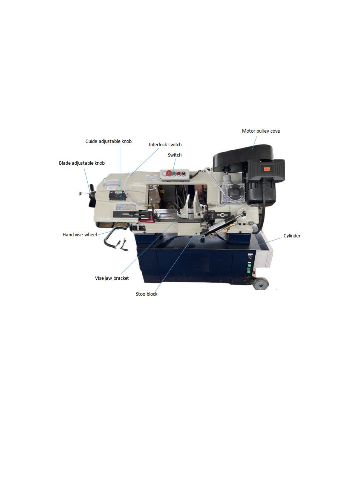
H. SAFETY DEVICE:
By the time the saw arm cover is opened, the interlock switch will function
to stop the machine, do not remove this switch from machine for any
reason, and check its function frequently.
1. SPECIFICATION
MOTOR
Saw Blade Speed
(MPM)
912B
60HZ
32 60 88 115
Saw Blade Speed
(FPM)
912B
60HZ
105 196 288 377
Blade Size
27X0.9X2655mm/1”X0.035”X104.5”
Dimension LxWxH(mm)
1380X460X1050(B)
N.W/G.W(kgs)
155/180(G..DR.GDR) 140/165(B)
Working Capacity
0°
O(mm)
230(9”)
□(mm)
178X305X(7”X12”)(G.B)
±45°
O(mm)
150(6”)(G.B)
□(mm)
127X150(5”X6”)(G.B)
Packing
Measurement(mm)LXWXH
1420X530X1100(B)
Overall height (w/o stand)
1600mm(63”)
Noise
80dB MAX

8
2. TRANSPORTATION OF MACHINE:
Unpacking
1. Transportation to desired location before unpacking, please use
lifting jack. (Fig. B)
2. Transportation after unpacking, please use heavy duty fiber belt to
lift p the machine.
ALLWAYS KEEP PROPER FOOTING &BALANCE WHILE
MOVING THIS MACHINE.
As this machine weight 155kg. It is recommended that the machine shall be
transported, with help of lifting jack.
Transportation Recommendation:
(1). Tighten all locks before
operation.
(2). Always Keep proper footing &
balance while moving this 155kgs
machine, and only use heavy duty
fiber to lift the machine as Fig. A
(3). TURN OFF the power before wiring, &be sure machine in proper
grounding, overload & circuit breaker is recommended for safety wiring.
(4). CHECK carefully if the saw blade is dunning in counter-clockwise
direction in not, reverse the wiring per circuit diagram the repeat the
running test.

9
(5). KEEP machine always out from sun, dust, wet, raining area.
6. MINIMUM ROOM SPACE FOR MACHINE OPERATION
7. MAKE PROPER TOOTH SELECTION
For maximum cutting efficiency and lowest cost pre cut, it is important to
select the blade with the right number of teeth per inch (TPI) for the
material being cut. The material size and shape dictate tooth selection.
TOOTH SELECTION
You need to consider
1. The width of the cut. That is the distance in the cut that each tooth must
travel from the point it enters the worpiece until it leaves the workpiece.
2. The shape of the workpiece.
●Squares, Rectangles, Flats (Symbol :■)

10
Locate the width of cut on the chart. (Inches on the outer circle and
millimeters on the inner circle.) Select the tooth pitch on the ring
marker with the square shape which aligns with the width of cut.
EXAMPLE: 6” (150mm) square, use a 2/3 Vari-Tooth.
●Round Solids (Symbol :■)
Locate the diameter of your workpiece on the chart. Select the tooth
pitch on the ring marked with the ring marked with the round shape
which aligns with the size of stock you are cutting.
EXAMPLE: 4” (100mm) round, use a 3/4 Vari-Tooth.
● Tubing, Pipe, Structural (Symbol: O H^)
Determine the average width of cut by dividing the area of the
workpiece by the distance the saw blade must travel to finish the cut.
Locate the average width of cut on the chart. Select the tooth Ditch on
the ring marked with the tubing and structural shape which aligns with
the average width you are cutting.
EXAMPLE: 4” (100mm) outside diameter, 3”(75mm) inside diameter
tubing. 4” (100mm) OD = 12.5 sq.In. (79c ㎡)
3” (75mm) I D =7.0 sq.In. (44c ㎡)
Area = 5.5 sq.In. (35c ㎡)
5.5 sq.In. (35c ㎡)/4” (100mm) distance =1.38(35mm) average width
1.38” (35mm), use a 4/6 Vari- Tooth
NOTE: The band speed and cutting rate recommendations presented on
this chart are approximations and are to be used as a starting point for
most applications. For exact sawing parameters’ consult your saw blade
supplier.
8. BI-METAL SPEEDS AND FEEDS

11
These figures are a guide to cutting 4”(100mm) material (with a 314
Vari-tooth when using a cutting fluid.
Increase Band Speed:
15% When cutting 1/4” (6.4mm) material (10/14 Vari-Tooth)
12% When cutting 3/4” (19mm) material ( 6/10 Vari-Tooth )
10% When cutting 1-1/4” (32mm) material ( 5/8 Vari-Tooth )
5% When cutting 2-1/2” (64mm) material ( 4/6 Vari-Tooth )
Decrease Band Speed:
12% When cutting 8” (200mm) material ( 2/3 Vari-Tooth )
MATERIAL
ALLOY ASTM NO
BAND SPEED
FT./MIN
M/MIN
Copper
Alloy
173,932
314
96
330,365
284
87
623,624
264
81
230,260,272
244
74
280,264,632,655
244
74
101,102,110,122,172
234
71
1751,182,220,510
234
71
625,706,715,934
234
71
630
229
70
811
214
65
Carbon
Steel
1117
339
103
1137
289
88
1141,1144
279
85
1141HI STRESS
279
85
1030
329
100

12
1008,1015,1020,1025
319
97
1035
309
94
1018,1021,1022
299
91
1026,1513
299
91
A36 (SHAPES),1040
269
82
1042,1541
249
76
Carbon
Steel
1044,1045
219
67
1060
199
61
1095
184
56
Ni-Ci-Mo
Alloy Steel
8615,86120,8622
239
73
4340,E4340,8630
219
67
Ni-Ci-Mo
Alloy Steel
8640
199
61
E9310
174
53
Tool Steel
A-6
199
61
A-2
179
55
A-10
159
49
D-2
90
27
H-11,H-12,H-13
189
58
Stainless
Steel
420
189
58
430
149
46
410,502
140
43
414
115
35
431
95
29
440C
80
24
304,324
120
36
304L
115
35
13
347
110
33
316,316L
100
30
416
189
58
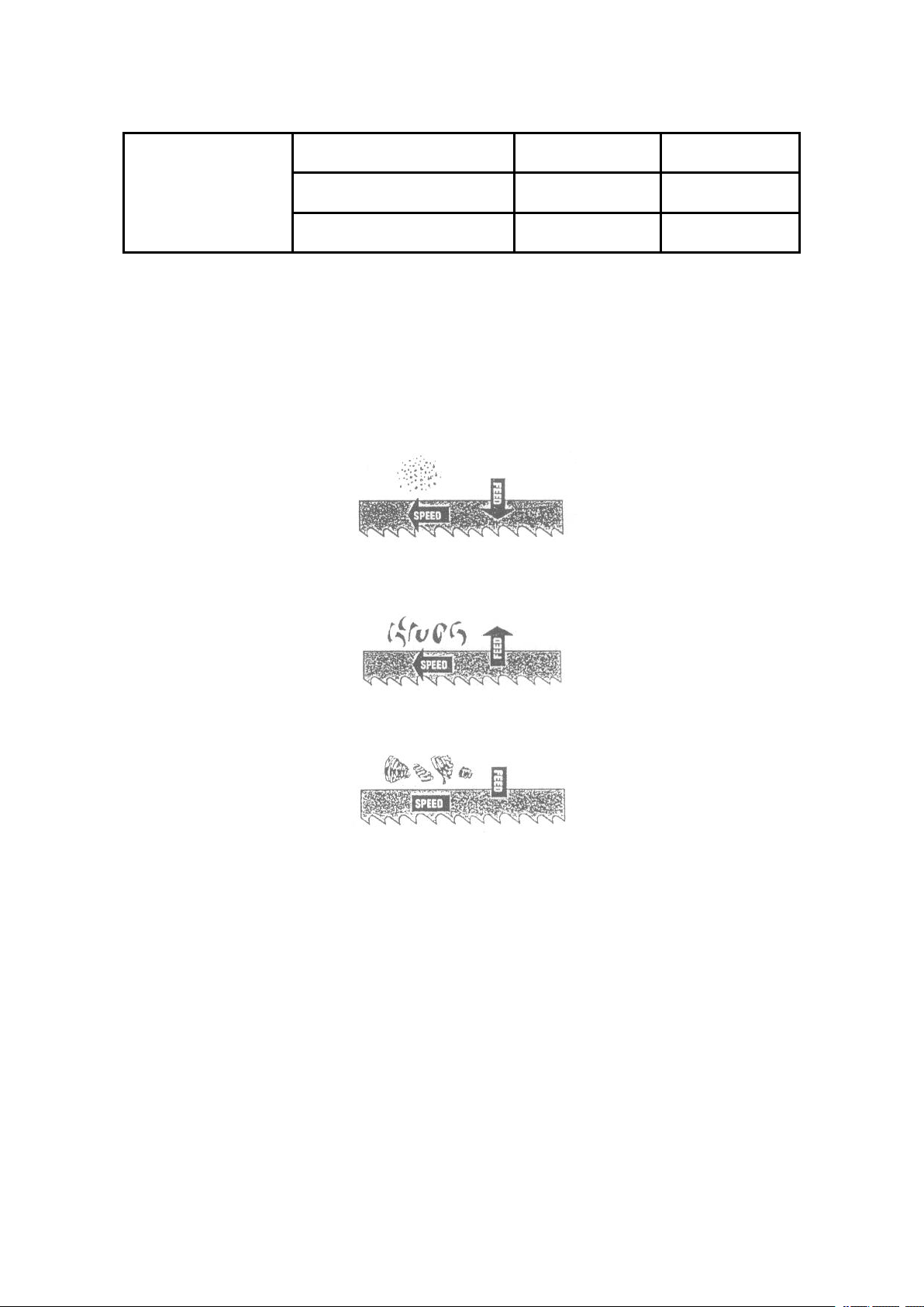
TELLTALE CHIPS
Chips are the best indicator of correct feed force. Monitor chip
information and adjust feed accordingly.
Thin or powdered chips-increase feed rate or reduce band speed.
Burned heavy chips-reduce feed rate and/or band speed.
Curly silvery and warm chips-optimum feed rate band speed.
9. ASSEMBLY
A 1 HP, motor, split phase or capacitor-start it recommended for best
economical performance. Counterclockwise rotation is required. Note that
rotation can be reversed by following directions given on terminal
nameplate.
(1). Assembly the motor Mounting plate to the head using the long bolt
Note that the flat side of the plate faces up.
(2). Assemble the guard plate to the head using the screw and Lock Washer
and the Carriage Bolt Washer and Wing Nut are used to secure the motor

14
mounting plate to the Guard plate through the slotted hole in the Guard
plate. These components also serve to position and lock the motor in place
for proper speed/ belt adjustment.
(3). Place the spacer over the long Bolt and secure it wit the nut.
(4). Secure the Motor to the Motor Mounting plate with the four bolts and
nuts. Note that the motor shaft is placed through the large opening in the
Guard plate and must be parallel with the drive Shaft.
(5). Assemble the Motor Pulley, the smaller of the two provided, to the
motor shaft Note, the larger diameter must be closest to the motor. Do not
tighten the set screw.
(6). Assemble the Driven Pulley, the larger of the two provided, to the
protruding drive Shaft Note the small diameter must be closest to the
bearing. Do not tighten the set screw.
(7). Place the belt into one of the pulley grooves and the other end into the
respective grooves of he second pulley.
(8). Line up the belt and both pulleys such that the belt is running parallel
in the pulley grooves.
(9). Tighten the set screws of both pulleys in this position.
(10). Place the belt into proper pulley combination for proper blade speed.
See material cutting chart.
(11). Adjust the position of the Motor to obtain approximately 1/2”
depression in the belt when applying pressure with you thumb.
(12). Tighten the head screw Holding the Motor Mounting plate to the
Guard plate.
(13). Connect the Electrical Harness to the motor terminal box. The motor
should be protected with a time delay fuse or circuit breaker with rated
amperage slightly greater than the full load amperage of the motor.
10. OPERATION

15
WORK SET UP
(1). Raise the saw head to the highest position.
(2). Open vise to accept the Piece to be cut by rotating the wheel at the
end the base.
(3). Place workpiece on saw bed. If the piece is long, support the end.
(4). Clamp workpieced securely in vise.
WORK STOP ADJUSTMENT
(1). Loosen the thumb screw holding the work stop casing to the shaf.
(2). Adjust the work stop casing to the desired length position.
(3). Rotate the work stop to as close to the bottom of the cut as
possible.
(4). Tighten thumbscrew.
(5). DO NOT ALLOW the blade to rest on the work while the motor is
shut off.
BLADE SPEEDS
When using your Band saw always change the blade speed to best suit
the material being cut the material Cutting Shirt givers suggested
settings for several materials.
Material
Speed F.P.M
Belt Groove Used
912(G.GDR)
912 (B.DR)
60Hz
50Hz
60Hz
50Hz
Motor
pulley
Saw
Pulley
Tool,Stainless
Alloy Steels
Bearing Bronze
125
104
105
85
small
largest
16
Medium to High
Carbon Steels
Hard Brass or
Bronze
Low to Medium
Carbon Steel
Soft Brass
255
212
196
164
Medium
Large
288
240
Large
Medium
Aluminum
Plastic
380
316
377
12
Largest
Small
MANUAL OF GEAR TYPE SPEED CHANGING
(1) Select the proper cutting speed according to the material of work-pieces
and blade select chart.
(2) Turn the speed-changing handle directly for the necessary speed.
(3) Changing speed during cutting is prohibited.
(4) But changing speed when machine is stopped and sunning (before
cutting)
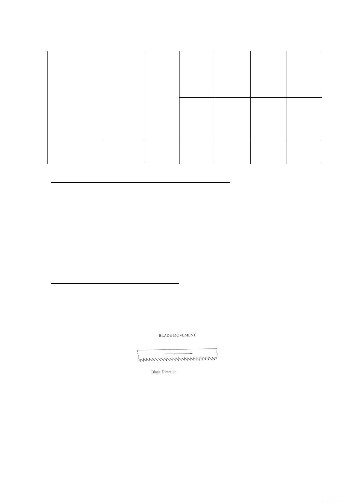
BALDE DIRECTION OF TRAVEL
Be sure the Made is assembled to the pulley such that the vertical edge
engages the work piece first.
BLADE MOVEMENT

17
STARTING SAW
Switch button function description
CAUIION : NEVER OPERATE SAW WITHOUT BLADE GUARDS IN
PLACE.
Be sure the blade is not in contact with the work when the motor is started.
Start the motor, allow the saw to come to full speed, and then begin the cut
by letting the head down slowly onto the work. DO NOT DROP OR
FORCE. Let the weight of the saw head provide the cutting fore. The saw
automatically shuts off at the end of the cut.
BLADE SELECTION
A 8-tooth per inch, general-use blade is furnished with metal Cutting Band
Saw. Additional blades in 4, 6, 8, and 10 tooth sizes are available. The
choice of lade pitch is governed by the thinness of the work to be cut: the
thinner the workpiece, the more teeth advised. A minimum of three (3)
teeth should angage to workpiece at all times for proper cutting. If the teeth
of the Blade are so far apart that they straddle the work, severe damage to
the workpiece and to the Made can result.
CHANGING BLADE
Raise saw head to the highest position and open the blade guards. Loosen
A (Emergency Push Button)
B (Start Button)
C (Stop Button)
D (Coolant Selection Switch)

18
tension screw knob sufficiently to allow the saw blade to slip off the wheels.
Install the new blade with teeth slanting toward the motor as follows:
(1). Place the blade in between each of the guide bearings.
(2). Slip the blade around the motor pulley (bottom) with the left hand
and hold in position.
(3). Hold the blade taut against the motor pulley by pulling the blade
upward with the right hand which is placed at the top of the Made.
(4). Remove left hand from bottom pulley and place is at the top aide of
the Made to continue the application on the upward pull on the blade
(5). Remove right hand from blade and adjust the position of the top
pulley to permit left hand to slip the blade around the pulley using
the thumb, index and little finger as guides.
(6). Adjust the blade tension knob clockwise until it is just right enough
so no blade slippage occurs. Do not tighten excessively.
(7). Replace the blade guards.
(8). Place 2-3 drops of oil on the blade.
TRU-LOCK VISE SYSTEM INSTRUCTIONS
(1). The position of the vise when tightened.
(2). The position of the vise when loosened. (Half opened).
(3). The position of the vise when loosened.(Completely opened).
To operate, proceed as follows:
1) Rise the arm 2”above the workpiece, close the cylinder valve to

19
maintain the arm 2”above the workpiece.
2) Put you workpiece on the table. Move the vise handle (a) upwards to
an angle of 45 degree (a-half opened) to loosen the vise. Move the
vise jaw bracket against the workpiece by turning the rectangular
handle (b). Push down on the vise handle (a) to lock the workpiece in
position.
3) To loosen the workpiece from the vise, hold the workpiece and lift the
vise handle (a) to a 90 degree position (completely opened). Remove
workpiece.
QUICK VISE ADJUSTMENT FOR ANGLE CUT (912B. 912G)
(1). Loosen the A. B. C. D. Screw.
(2). Adjust rear vise to the threaded hole position. (E)
(3). Set the scale to the desired angle.
(4). Adjust he front vise (F) to parallel the rear vise (E)
(5). Tighten the A. B. C. D. Screw.
QUICK VISE ADJUSTMENT FOR ANGLE CUT (912DR. 912GDR)
(1). Pull out plastic knob (A). Turn and lock the plastic knob.
(2). Loosen grip (B) .Then rotate the Body Frame for the desired angle.
Be aware the blade position is higher than the Vise Table by
pulling up the Body Frame when count-clockwise rotation for
angle cutting and for clockwise rotation for angle cutting higher
the Body Frame and keep the blade position higher than the vise.
Then pull forward the vise Jaw Bracket (Front) to a proper

20
location.
(3). Fasten the grip (B) when the cutting angle is reached.
(4). There is angle set-screw for ±45° rotation.
11. BLADE GUIDE BEARING ADJUSTMENT
ATTENTION: This is the most important adjustment on your saw. It is
impossible to get satisfactory work from your saw if the blade guides are
not properly adjusted. The blade guide bearing on your metal. Cutting Band
Saw are adjusted and power tested with several test cuts before leaving the
factory to insure proper setting. The need for adjustment should rarely
occur straight, and if the situation is not corrected it will cause serious
blade damage. Because guide adjustment is a critical factor in the
performance of your saw, it is always best to try a new blade to see if this
will correct poor cutting before beginning to adjust. If a blade becomes dull
on one side sooner than the other, for example, it will begin cutting crooked.
A blade change will correct this problem the guide adjustment will not. If a
new blade does not correct the problem, check the blade guides for proper
spacing.
NOTE: There should be from 000(just touching) 001 clearance between the
blade and guide bearings to obtain this clearance adjust as follows:
1. The inner guide bearing is fixed and cannot be adjusted.
2. The outer guide bearing is mounted to an eccentric bushing and can
be adjusted.
3. Loosen the nut while holding to an eccentric bushing and can be
This manual suits for next models
4
Table of contents
Other Toolots Saw manuals


