Toolshop 240-1575 User manual
UNIVERSAL TOOL TABLE
240-1575
Owner’s Manual
PRODUCT SPECIFICATIONS
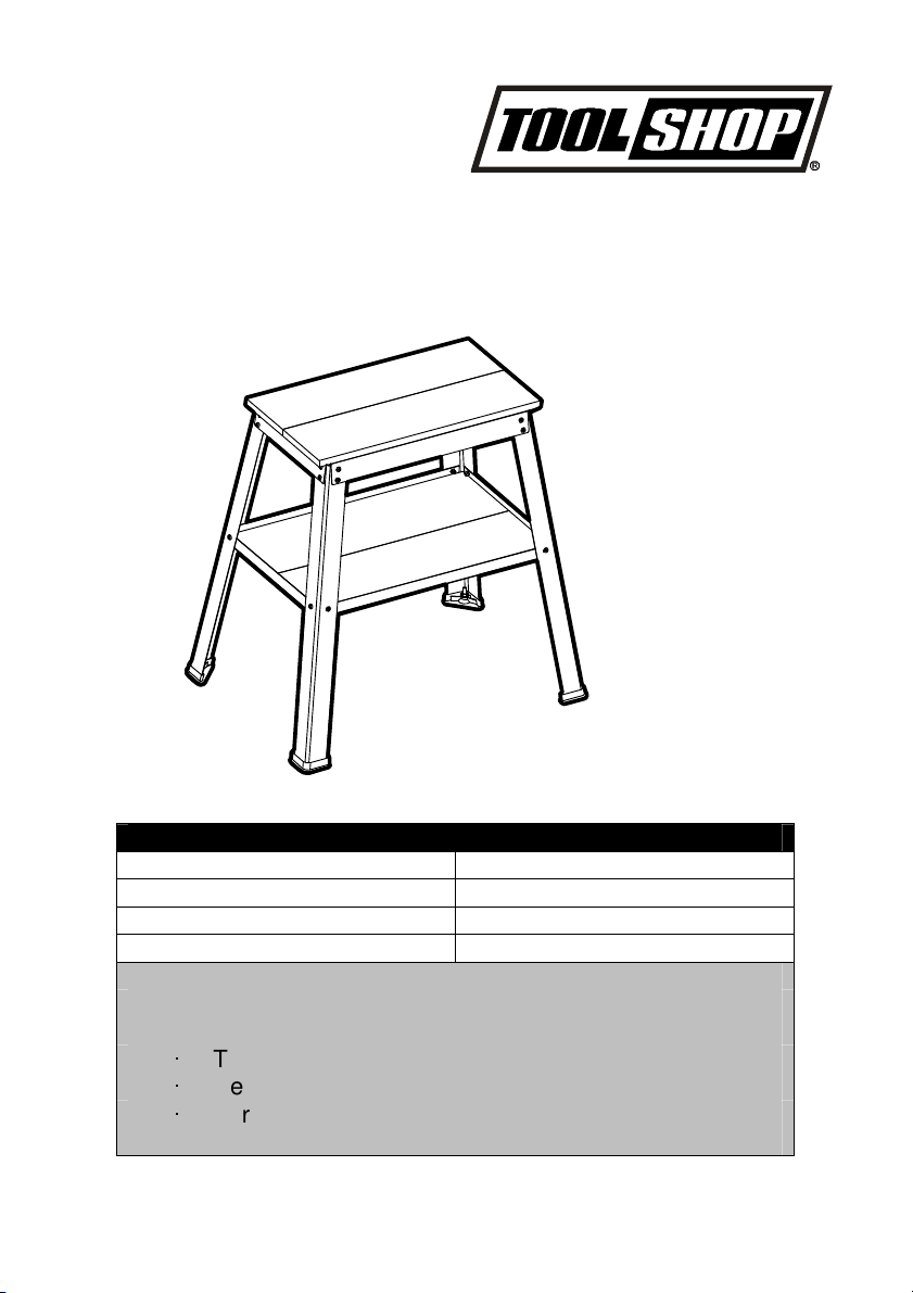
Work station tabletop size: 14” x 25”
MDF lower shelf 18” x 27”
Working height 32”
Max. weight capacity 500 lb.
Need Assistance?
Call us on our toll free customer
support line:
1
-
866
-
349
-
8665
Technical questions
Replacement parts
Parts missing from package

TABLE OF CONTENTS
Product
Product specifications……………………………....………………... ……………............. 1
Table of contents…………………………………………..……………....…..…................ 2
Safety instructions……………………………………….... ……………....…………...…. . 3
Safety symbols…………...……………………………….... ……………....…………….. . 4-6
Description……………………………………………….... ……………....…...…………. . 6
Assembly………………………………………………….... ……………....……………… 7-8
Operation……………………………………………….... ……………....………………… 9-11
Maintenance………………………………………….... ……………....…………………….. 12
Exploded view……………………………………….... ……………....…………………….13
Parts list……………………………………………….... ……………....…………………….14
Warranty…………………………………………….... ……………....………………………..15

SAFETY INSTRUCTIONS
GENERAL SAFETY RULES
WARNING:
Read all safety warnings and instructions. Failure to follow the warnings and
instructions may result in electric shock, fire and/or serious injury.
Save all warnings and instructions for future reference.
READ AND SAVE THESE INSTRUCTIONS
WARNING:
Do not modify this tool and/or use it for any application other than that for which it
was designed.
Do not use for scaffolding or as ladder. Do not stand or climb on the bench top work station; it
could tip over, causing serious injury.
Do not overload. The maximum capacity for the bench top work station is 500lbs.
Do not apply an unbalanced load. This could cause the bench top work station to tip over.
Store the stand properly. Do not store the bench top work station outdoors or in a damp
location.
Keep the work area clean, uncluttered, and well lit. Do not work on or place the bench top
work station legs on floor surfaces that are slippery from sawdust, oil, water or wax.
Keep children and bystanders away while operating a power tool. Distractions may cause
you to lose control. Visitors should wear the same safety equipment as the operator.
When using a power tool with the bench top work station, always follow the safety
instructions in the power tool’s Operator’s Manual.
Always wear safety glasses or eye shields when operating power tools.
Dress properly. Do not wear loose clothing or jewelry. Keep your hair, clothing and gloves
away from moving parts. Loose clothes, jewelry or long hair can be caught in moving parts.
Always wear non-slip footwear. Tie back long hair. Roll long sleeves above the elbow.
Always use clamps or other practical ways to support the work piece and secure it to a stable
platform. Holding the work by hand or against your body is unstable and may lead to loss of
control.

SAFETY SYMBOLS
WARNING:
Be sure to read and understand all safety instructions in this Operator’s Manual,
including all safety alert symbols such as “DANGER”, “WARNING”, and “CAUTION” before using
this tool. Failure to following all instructions listed below may result in electric shock, fire, and/or
serious personal injury.
SYMBOL MEANING
SAFETY ALERT SYMBOL: Indicates DANGER, WARNING, OR CAUTION. May be used in
conjunction with other symbols or pictographs.
DANGER:
Indicates an imminently hazardous situation, which, if not avoided, will result in
death or serious injury.
WARNING:
Indicates a potentially hazardous situation, which, if not avoided, could result in
death or serious injury.
CAUTION:
Indicates a potentially hazardous situation, which, if not avoided, could result in
minor or moderate injury.
Damage Prevention and Information Messages
These inform the user of important information and/or instructions that could lead to equipment or
other property damage if they are not followed. Each message is preceded by the word “NOTICE,”
as in the example below:
NOTICE:
Equipment and/or property damage may result if these instructions are not followed.
WARNING:
To ensure safety and reliability, all repairs should be performed by a qualified
service technician.
WARNING:
The operation of any power tools can result in foreign objects being thrown into
your eyes, which can result in severe eye damage. Before
beginning power tool operation, always wear safety goggles or safety glasses
with side shield and a full face shield when needed. We recommend a Wide
Vision Safety Mask for use over eyeglasses or standard safety glasses with
side shields. Always use eye protection which is marked to comply with ANSI
Z87.1.

SAFETY SYMBOLS
SAVE THESE INSTRUCTIONS
Some of the following symbols may be used on this tool. Please study them and learn their
meaning. Proper interpretation of these symbols will allow you to operate the tool better and more
safely.
SYMBOL NAME DESIGNATION/EXPLANATION
V Volts Voltage
A Amperes Current
Hz Hertz Frequency (cycles per second)
W Watt Power
Min Minutes Time
Alternating Current Type of current
Direct Current Type or a characteristic of current
n
o
No Load Speed Rotational speed, at no load
Class II
Construction
Double-insulated construction
…/min Per Minute Revolutions, strokes, surface speed, orbits, etc., per
minute
Wet Conditions
Alert
Do not expose to rain or use in damp locations.
Read The
Operator’s Manual
To reduce the risk of injury, user must read and
understand operator’s manual before using this product.
Eye Protection Always wear safety goggles or safety glasses with side
shields and a full face shield when operating this
product.
Safety Alert Precautions that involve your safety.
No-Hands Symbol Failure to keep your hands away from the blade will
result in serious personal injury.
SAFETY SYMBOLS
No-Hands Symbol Failure to keep your hands away from the blade will
result in serious personal injury.
No-Hands Symbol Failure to keep your hands away from the blade will
result in serious personal injury.
No-Hands Symbol Failure to keep your hands away from the blade will
result in serious personal injury.
Hot Surface To reduce the risk of injury or damage, avoid contact with
any hot surface.
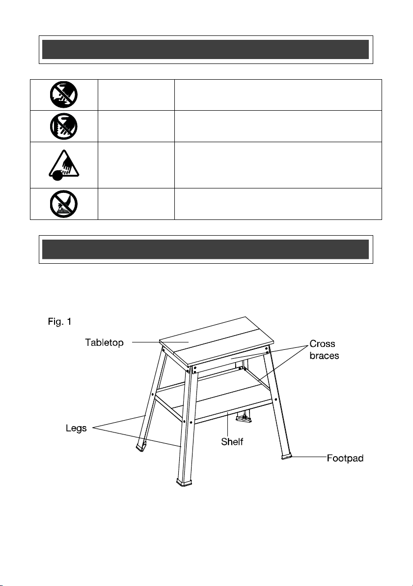
DESCRIPTION
KNOW YOUR WORK STATION (Fig.1)
ASSEMBLY
WARNING:
If any parts are broken or missing, do not attempt to operate the work station
until the broken or missing part is replaced. Failure to do so could result in serious injury.
WARNING:
Do not attempt to modify this work station or create accessories not
recommended for use with this work station. Any such alteration or modification is misuse and
could result in a hazardous condition leading to serious injury.
UNPACKING
This product has been shipped disassembled.
Carefully remove all the parts and accessories from the carton. Make sure that all items in
the packing list are included.
Inspect the parts for the work station carefully to make sure that no breakage or damage
occurred during shipping.
Do not discard the packing material until you have carefully inspected and satisfactorily
operated the work station.
If any parts are damaged or missing, please return the work station to the place of purchase.
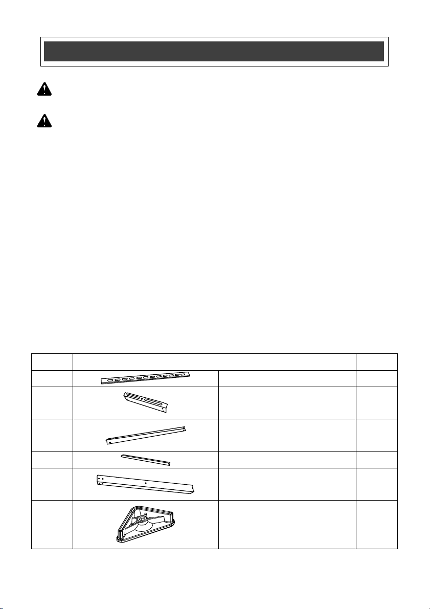
PACKAGE CONTENTS AND HARDWARE
Item Description Qty.
A
Long upper cross brace 2
B
Short upper cross brace 2
C
Long lower cross brace 2
D Short lower cross brace 2
E
Log 4
F
Footpad 4

ASSEMBLY
Item Description Qty.
G
Tabletop, rear 1
H
Tabletop with scale, front 1
J
Shelf 2
K
Pan head screw (M6x10) 24
L
Nut (M6) 24
M
Countersink screw (M8x40) 1
N
Nut (M8) 2
P
Pad 1
Q
Washer 8mm 1
R
Pan head wood screw (ST5.8x14) 10
S
Washer 6mm 12

OPERATION
WARNING:
Do not use this tool for scaffolding or as a ladder. Make sure to tighten all screws
securely prior to use. Maximum capacity is 500lbs.
ASSEMBLING THE LOWER AND UPPER
CROSS BRACES TO THE LEGS
NOTICE:
Use pan head screws(K) And nuts(L) to assembly
all components except the tabletop and leveling device.
NOTICE:
Initially, loosely assemble the metal components.
Fully tighten components at the end of the assembly process.
1. Assemble a long upper cross brace (A) to the two legs (E)
(Fig.2). Screw connections as shown in Fig.2a
2. Assemble a long lower cross brace (C) to two legs (E).
Fig.3 Make sure that the lower cross braces are
positioned as shown in Fig.3a so that the flange can
cradle the lower shelf and the mitered corners of the
flange are positioned as shown.
3. Repeat steps 1 and 2 to assemble the other two legs
(E).
4. Connect the four legs by assembling two short upper
cross braces (B) and two short lower cross braces (D)
(Fig.4)
5. Tighten all fasteners completely.
OPERATION
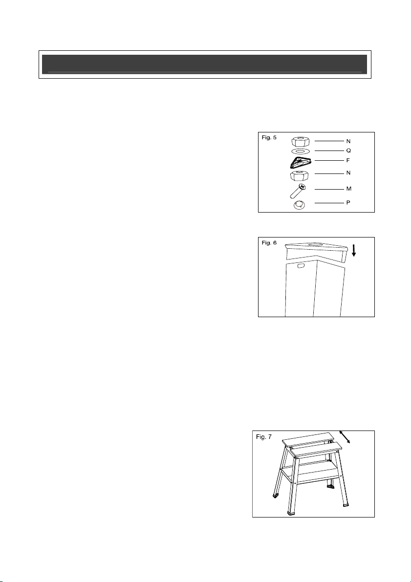
ASSEMBLING LEVELING DEVICE (Fig.5)
Assemble the leveling device into one of the footpads.
1. Insert countersink screw (M) into pad(P).
2. Thread countersink screw (M) with pad (P) into first nut
(N).
3. Place washer (Q) and second nut (N) on top of footpad
(F). Thread countersink screw (M) through footpad (F),
washer (Q), and second nut (N).
Attach Footpads
Slide one footpad (F) onto the bottom of each leg. (One
footpad will include the leveling device.)
Align the large corner radius of the footpad and the corner
radius of footpad on angle as shown in Fig.6.
Leveling
To level the work station on an uneven surface, turn the screw in the leveling device. Move the
leveling device in and out to raise or lower the level of the footpad.
NOTICE:
If necessary, interchange position of footpads on the work station in order to obtain
maximum leveling capability.
ASSEMBLING THE TABLETOP
Assemble the tabletop in one of three positions. For a solid
surface, place the edges of the boards together. The
remaining two positions are for mounting larger bench tools
(Fig.7)
To assemble the tabletop:
1. Place the two, thick boards (G,H) print-side-down on a
flat surface and spaced to fit the mounting footprint of your tool (Fig.8).
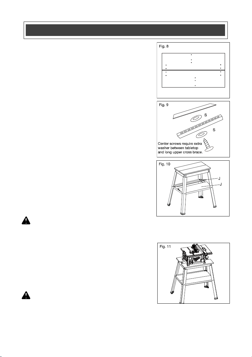
OPERATION
2. Place the assembled frame upside-down onto the table
tops. Thread the pan-head wood screws (R) with
washers (S) through slots in the brace and into the five
holes in each tabletop.
NOTICE: The center screws lock the tabletops in position and
have one washer (S) on the screw head and one additional
washer (S) between the long upper cross brace and the
tabletop (Fig.9).
ASSEMBLING THE SHELF (Fig.10)
NOTICE:
The lower cross braces should be oriented so that
the flange extends from the lower portion of the cross base
cradle the lower shelf (refer to Fig.3a).
1. The shelf comes in two pieces (J). Slide one piece onto
the flange and underneath the cross brace bolts.
2. Slide the second piece onto other side.
APPLICATIONS (Fig.11)
WARNING:
Do not use the work station for scaffolding or as a ladder. Make sure to securely
tighten all fasteners before using. Maximum capacity is 500 lbs. Power tools on the work station
should not exceed a combined overall height of 60inches
from the floor.
To use the work station with a table saw, use the largest
opening so debris does not accumulate.
Drill holes as needed into the tabletop. Mount all power tool
with nuts and bolts (not supplied).
CAUTION:
Be careful not to drill the cross braces when
drilling holes.

MAINTENANCE
WARNING:
When servicing, use only identical replacement parts. User of any other parts
may create a hazard or cause product damage.
GENERAL MAINTENANCE
Avoid using solvents when cleaning plastic parts. Most plastics are susceptible to damage from
various types of commercial solvents and may be damaged by their use. Use clean clothes to
remove dirt, dust, oil, grease, etc.
WARNING:
When servicing, use only identical replacement parts. Use of any other parts
may create a hazard or cause product damage. To ensure safety and reliability, all repairs should
be performed by a qualified service technician.
WARNING:
Keep the work station dry, clean, and free from oil and grease. Always use a
clean cloth when cleaning. Never use brake fluids, gasoline, petroleum based products or any
strong solvent to clean the work station. Chemicals can damage, weaken or destroy plastic which
may result in serious personal injury.
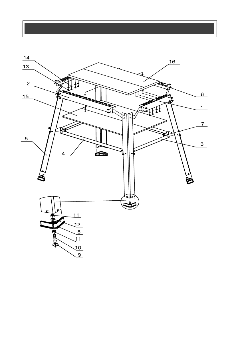
EXPLODED VIEW

PARTS LIST
No Part No Part Name QTY
1 240-1575-1 Short upper cross brace 2
2 240-1575-2 Long upper cross brace 2
3 240-1575-3 Short lower cross brace 2
4 240-1575-4 Long lower cross brace 2
5 240-1575-5 Leg 4
6 240-1575-6 Pan head screw( M6x10) 24
7 240-1575-7 Nut (M6) 24
8 240-1575-8 Footpad 4
9 240-1575-9 Pad 1
10 240-1575-10 Countersink screw (M8x40) 1
11 240-1575-11 Nut (M8) 2
12 240-1575-12 Washer ø8mm 1
13 240-1575-13 Pan head wood screw (ST5.8x14) 10
14 240-1575-14 Washer ø6mm 12
15 240-1575-15 Shelf 2
16 240-1575-16 Tabletop, front/ Tabletop, rear 2
WORK STATION MODEL NO. 240-1575
The model number will be found on the nameplate attached to the leg of
the work station. Always mention the Model Number when ordering parts
for this tool.

TOOL SHOP
®
UNIVERSAL TOOL TABLE
WARRANTY
1-YEAR LIMITED WARRANTY:
This TOOL SHOP
®
brand tool carries a 1-Year Limited Warranty to the original purchaser. If the tool
fails within one (1) year from the date of purchase, simply bring this tool with your original sales
receipt back to your nearest MENARDS® retail store. At its discretion, TOOL SHOP® agrees to
have the tool replaced with the same or similar TOOL SHOP® product free of charge, within the
stated warranty period, when returned by the original purchaser with original sales receipt.
Notwithstanding the foregoing, this limited warranty does not cover any damage that has resulted
from abuse or misuse of the Merchandise. This warranty: (1) excludes expendable parts including
but not limited to blades, belts, bits, light bulbs, and/or batteries; (2) shall be void if this tool is used
for commercial and/or rental purposes; and(3) does not cover any losses, injuries to
persons/property or costs. This warranty does give you specific legal rights and you may have
other rights, which vary from state to state. Be careful, tools are dangerous if improperly used or
maintained. Seller’s employees are not qualified to advise you on the use of this Merchandise. Any
oral representation(s) made will not be binding on seller or its employees. The rights under this
limited warranty are to the original purchaser of the Merchandise and may not be transferred to any
subsequent owner. This limited warranty is in lieu of all warranties, expressed or implied including
warranties or merchantability and fitness for a particular purpose. Seller shall not be liable for any
special, incidental, or consequential damages. The sole exclusive remedy against the seller will be
for the replacement of any defects as provided herein, as long as the seller is willing or able to
replace this product or is willing to refund the purchase price as provided above. For insurance
purposes, seller is not allowed to demonstrate any of these tools for you.
For questions/comments, technical assistance or repair parts-
Please call toll free at: 1-866-349-8665 (M-F 8am-6pm)
SAVE YOUR RECEIPTS. THIS WARRANTY IS VOID WITHOUT THEM.
Distributed by: Menard, lnc., Eau Claire, WI 54703
Table of contents
Popular Tools Storage manuals by other brands

IAC INDUSTRIES
IAC INDUSTRIES QS-930 Assembly instructions

Beta
Beta C39T-O Instructions for use

brennenstuhl
brennenstuhl MB 120 KH Operation and safety notes

Whalen
Whalen WSMTB48-W manual

ATD Tools
ATD Tools ATD-70320 owner's manual

Tennsco
Tennsco Industrial Workbench with Hardwood Butcher Block... Assembly Instructions/Parts Manual

Pinnacle
Pinnacle PRO Series quick start guide

Dura-Max
Dura-Max 68006 quick guide

Sealey
Sealey AP28104 instructions

brennenstuhl
brennenstuhl AMB200 Operation and safety notes

Kval
Kval Commander instruction manual

Seville Classics
Seville Classics HOME UltraGuard Workcenter Island UHD20109 Assembly instructions


