TOP CAT WP-4 PRO User manual

USE MANUAL
WP-4 PRO BUBBLE FOG MACHINE
- 1 -
1 BEFORE YOU BEGIN
1.1 What Is Included
WP-2 bubble fogger × 1 Power Cord × 1 W-2 wireless remote × 1
Omega Bracket × 1 Warranty Card × 1
1.2 Unpacking Instructions
Carefully unpack the product immediately and check the container to make sure all the parts are in the
package and are in good condition.
If the box or the contents (the product and included accessories) appear damaged from shipping, or show
signs of mishandling, notify the carrier or dealer/seller immediately. In addition, keep the box and contents
for inspection.
1.3 Symbols
Symbol
Meaning
Caution
Critical installation, configuration, or operation information. Not following these instructions may
make the product not work, cause damage to the product, or cause harm to the operator.
Important
Important installation or configuration information. Failure to comply with this information may
keep the product from working correctly.
Information
Useful information.
1.4 Disclaimer
The information and specifications contained in this User Manual are subject to change without notice.
DJPOWER assumes no responsibility or liability for any errors or omissions and reserves the right to revise or
to create this manual at any time. Copyright © 2019 DJPOWER. All rights reserved.
1.5 Safety Notes
Please read the following Safety Notes carefully before working with the product. The notes include
important safety information about installation, usage, and maintenance.
1.5.1 Personal Safety
• Always connect the product to a grounded circuit to avoid the risk of electrocution.
• Make sure that children, unauthorized people and animals do not obtain access to the machine.
1.5.2 Mounting and Rigging
• The product is for indoor use only! To prevent risk of fire or shock, do not expose the product to rain or
moisture.

- 2 -
• CAUTION: When transferring product from extreme temperature environments, (e.g. cold truck to warm
humid ballroom) condensation may form on the internal electronics of the product. To avoid causing a
failure, allow product to fully acclimate to the surrounding environment before connecting it to power.
• Do not mount the product on a flammable surface (linoleum, carpet, wood, paper, carton, plastic, etc.).
• Do not use in a confined space. Always install the product in a location with adequate ventilation, at least
20 in (50 cm) from adjacent surfaces.
• Be sure that no ventilation slots on the product’s housing are blocked or clogged by dust. If necessary,
remove the dust.
1.5.3 Power and Wiring
• Always make sure that the voltage of the outlet to which you are connecting the product is within the
range stated on the decal or rear panel of the product.
• Make sure the power cord is not crimped or damaged.
• Never connect this product to a dimmer pack or rheostat.
• Never disconnect the product from power cord by pulling or tugging on the cord.
• To eliminate unnecessary wear and improve its lifespan, during periods of non-use completely
disconnect the product from power via breaker or by unplugging it
1.5.4 Operation
• Do not operate this product if you see damage to the housing or cables. Have the damaged parts
replaced by an authorized technician at once.
• Do not use the product as a space heater.
• The maximum ambient temperature (Ta) is 104 °F (40 °C). Do not operate the product at higher
temperatures.
•Do not cover the ventilation slots when operating to avoid internal overheating.
•Do not cover or plug the output nozzle during operation.
• Wipe up spitted fluid immediately. Moisture – also fluid – can destroy the electric.
• Never carry the product by the power cord or any moving part. Always use the handles of the machine.
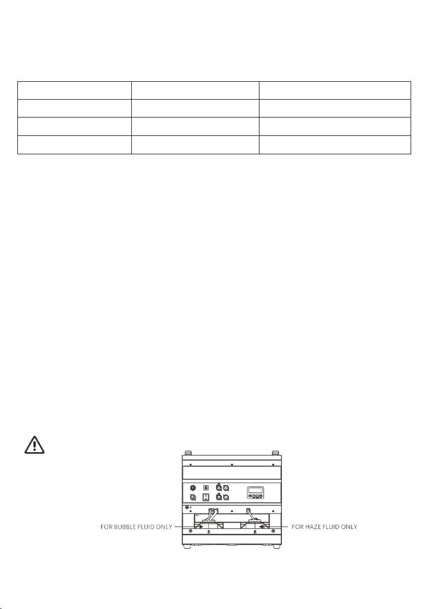
•Drain the tank before transporting the product. Bubble fluid or the fog fluid tanks shall be used for
the relevant fluid only.
• Always disconnect the product from the power source before cleaning.
• In the event of a serious operating problem, stop using the product immediately.
• This product contains no user-serviceable parts. Any reference to servicing in this User Manual will only
apply to properly trained, certified technicians. Do not open the housing or attempt any repairs which
can lead to damage or malfunction.
•Use only DJPOWER Consumable. Bubble fluid PRO-P and fog fluid PRO-C are recommended.
Keep this User Manual for future use. If you sell the product, be sure that the purchaser receives
this document.

- 3 -
2 INTRODUCTION
2.1 Description
WP-2 bubble fog machine is the first bubble blaster from DJPOWER. It comes with patented Jet-design
which creates lot of vivid bubbles filled with fog while with less fog outside. The excess bubble fluid will flow
back to waste storage bin instead of dropping on the ground. To protect bubble fluid from getting bad and
ensure high quality bubbles, bubble fluid is well stored in the tank. With this feature, the unit can also be
mounted high in the truss, launching bubbles dancing all over the sky. No matter for shows, concerts, parties
and events, this unit will be pretty good choice.
2.2 Features
• Jet design, producing lots of bubbles filled with fog.
• Well-designed heating system, releasing the fog evenly and purely, no fluid dropping off.
• Dual fan, spreading bubbles to higher air and further.
• Groove beneath the nozzles for placing absorbent cotton, absorbing the spitting bubble fluid.
• The excess bubble fluid will flow back to waste fluid tank.
• Combining with Led light, matching with bubble fogger to achieve more amazing effect.
• ON-board LCD control panel, user friendly
2.3 Product Overview

- 4 -
2.4 Product Dimensions
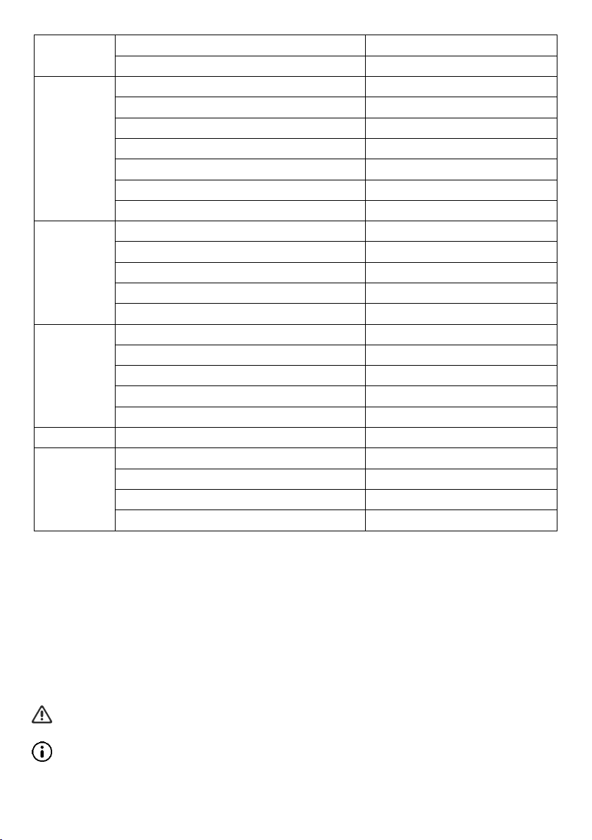
3 TECHNICAL SPECIFICATIONS
AC Power
Input Voltage & Rate
AC 220-240 V, 50/60 Hz
Current Limiter Type
Breaker
Current Limiter Specifications
5 A, 250 V
Total Power Consumption
650 W
Heating
Heat Up Time
Appr. 3 min
Light Source
LED Color
RGBY
LED Type
Quad-Color
Power per LED
8 W
Quantity of LED
6 pcs
Total LED Power
48 W
- 5 -
4 SETUP
4.1 AC Power
The machine has a fixed voltage power supply and can work with an input voltage of AC 110V-120V,
50/60Hz or AC 220 V-240 V, 50/60 Hz, depending on the specific model.
To determine the product’s power requirements (circuit breaker, power outlet, and wiring), use the current
value listed on the label affixed to the product’s back panel, or refer to the product’s specifications chart. The
listed current rating indicates the product’s average current draw under normal conditions.
Always connect the product to a protected circuit (circuit breaker or fuse). Make sure the
product has an appropriate electrical ground to avoid the risk of electrocution or fire.
Never connect the product to a rheostat (variable resistor) or dimmer circuit, even if the rheostat
or dimmer channel serves only as a 0 to 100% switch.
Capacity
Bubble Fluid Tank Capacity
1.3 L
Fog Fluid Tank Capacity
1.3 L
Output
Adjustable Output
√
Max Fog Output Volume
Appr. 4,500 cuft/min
Max Output Height
Appr. 4 m
Max Output Distance
Appr. 3.5 m
Fog Fluid Consumption (100% Output)
Appr. 60 min/L
Bubble Fluid consumption (100% Output)
Appr. 40 min/L
Consumable Type for Standard Output Test
PRO-PW and PRO-C and PRO-J
Placement
& Mounting
Horizontal
√
Inclined
×
Sidelong
×
Hang Upside Down
×
Rigging & Trussing
√
Control
On-device Manual Control
LCD control board
Wireless Control
√
Wired Control
×
Control Protocol
DMX512
DMX Channel Range
12
Consumable
Consumable
PRO-PW and PRO-C and PRO-J
Weight &
Dimensions
Net Weight
14.5 kg
Gross Weight
17 kg
Machine Dimensions
426 × 317 × 394 mm
Packing Dimensions
535 × 435 × 500 mm
- 6 -
4.2 AC Plug
The WP-2 comes with a power input cord terminated with a Seetronic Powerkon connector on one end and
an EU plug on the other end (EU market). If the power input cord that came with your product has no plug,
or if you need the change the plug, use the table below to wire the new plug:
Connection
Wire (U.S.)
Wire (Europe)
AC Live
Black
Brown
AC Neutral
White
Blue
AC Ground
Green
Green/Yellow
4.3 Resetting the Breaker
This product is equipped with a resettable breaker. If the breaker trips, all sections of this product will lose
power.
• Remove the power cord from mains power.
• Allow unit to cool for 15 minutes.
• After 15 minutes, you may attempt to reset the breaker by pressing the button with your finger.
• Plug the product’s power cord into the power outlet and continue using as recommended.
4.4 DMX Linking
You can link the WP-2 to a DMX controller using a 3- or 5-pin DMX connection. If using other DMX-
compatible products with this product, you can control each individually with a single DMX controller.
Instructions for connecting and configuring this product for DMX operation are in the User Manual.
4.5 Mounting
Before mounting the product, read and follow the safety recommendations indicated in the Safety Notes.
4.5.1 Orientation
For safety reasons, we do not recommend mounting the product in any capacity. Operate the product while
it is on the ground only, and make sure there is adequate room for ventilation, configuration, and
maintenance.
Do not mix bubble fluid and fog fluid.
4.5.2 Rigging
DJPOWER recommends using the following general guidelines when mounting this product.
- 7 -
• Before deciding on a location for the product, make sure there is easy access to the product for
maintenance and programming purposes.
• Make sure that the structure or surface onto which you are mounting the product can support the
product’s weight (see the Technical Specifications).
• When mounting the product on the floor, make sure that the product and cables are away from people
and vehicles.
5 OPERATION
5.1 Preparing for Operation
• After checking that all the parts are intact and complete, position the machine on flat.
• Withdraw the fluid tank from its compartment and remove its cap.
• Verify that the plastic hoses attached to the cap are in place and in good condition without bending or
warp.
• Always connect the product to a grounded circuit. Before power on, make sure it is connected with the
rated voltage.
• Turn on the machine, and “ Heating up” shows on the display during the heating-up process. After
approx. 3 minutes, the display changes to “Ready to work” when the machine is ready to output.
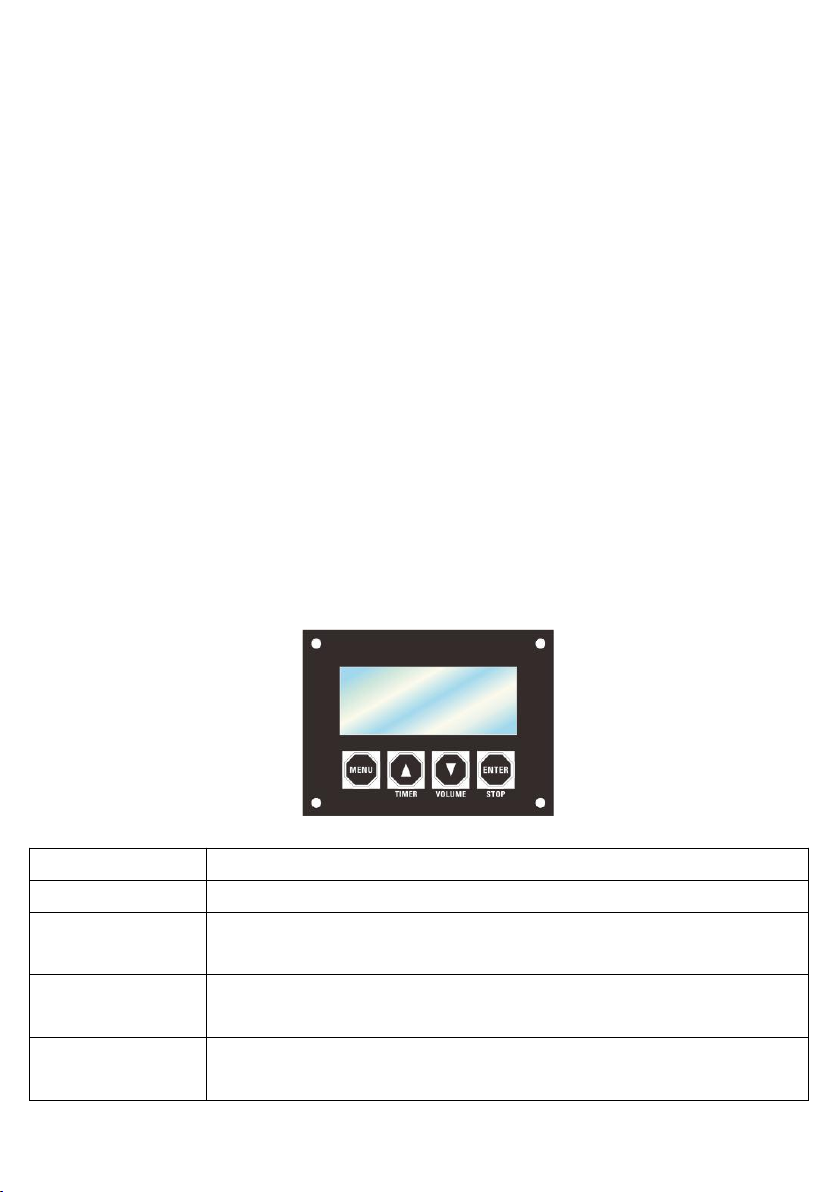
5.2 On-device Control Panel
To access the control panel functions, use the four buttons located underneath the LCD display.
Button
Function
<MENU>
Switch menu pages to select a function
<TIMER>
Increases the numeric value of current function
Triggers Timer output mode
<VOLUME>
Decreases the numeric value of current function
Triggers Manual output mode.
<STOP>
Save settings
STOP turns the fog output off

- 8 -
5.2.1 Menu Map
LCD display
Description
Ready To Work
After about a minutes heating, it will show this page.
Interval Set
Press UP or DOWN button to set interval of TIMER mode
5~200s
Duration Set
Press UP or DOWN to set duration of TIMER mode
5~200s
Bubble Output
Press UP or DOWN to set Bubble output
ON /OFF
Haze Output
Press UP or DOWN to set haze volume
1%~100%
Fan Speed
Press UP or DOWN to set fan speed
1%~100%
LED Colour
Press UP or DOWN to select color
1. Red
2. Green
3. Blue
4. Amber
5. Orange
6. Purple
7. Sky blue
8. Color Marco
DMX512 Address
Press UP or DOWN to set DMX address
1~512
Clean Mode
Press UP or DOWN to set cleaning mode
ON/OFF
(When cleaning mode is ON, it will override all the other functions. Default cleaning
time is 1 minute without turning of the mode manually.)
Language
Press UP or DOWN to select language
English/Chinese
Under Timer or Volume Mode, the working status is based on bubble output, haze output, wind
output and LED color set by the LCD control board.
5.3 Wireless Remote-Control Mode & Operation
This mode will allow you to control the bubble fogger using the wireless controller W-2. This consists of the
transmitter and the receiver. Any one(or more) W-2 transmitter can work with any one (or more) W-2
receiver, no pairing procedure needed.
You may control up to 4 independent bubble fogger or more if you run them simultaneously. See the below
instructions on setting up you bubble fogger WP-2 to operate with the W-2.

- 9 -
Wireless Receiver Wireless transmitter
When use W-2 wireless remote controller, the working status is based on bubble output, haze
output, wind output and LED color set by the LCD control board.
• Plug the wireless receiver into the bubble fogger 5-pin port labeled “Wireless Controller”. The red LED
indicator will be on when the transmitter is successfully connected. There is no any reaction in the green
LED indicator.
• There are 4 buttons on the wireless remote transmitter which act as triggers. Each button can be
assigned to a different Bubble fogger WP-2. You may only choose 1 dipswitch on each receiver. See the
below configuration options for setting the receivers to operate with the transmitter remote.
• Press the button, and the Bubble fogger WP-2 will run momentarily for as long as you hold down the
button• Release the button, the unit stops running.
5.4 DMX Mode & Operation DMX
The machine WP-2 works with a DMX controller.
• Connect the product to a suitable power outlet
• Turn the product on.
• Connect a DMX cable from the DMX output of the DMX controller to the DMX input socket on the
product.
Staring Address
When selecting a starting DMX address, always consider the number of DMX channels. If you choose a
starting address that is too high, you could restrict the access to some of the product’s channels.
DJPOWER WP-2 DMX set the stating address in the 001 - 512 DMX range and uses 12 DMX
channels, which defines the highest configurable address to 501 to have all channels
controllable.
Connect a DMX cable from the DMX output of the DMX controller to the DMX input socket on
the product, or press repeatedly “MENU” button until the LCD shows “DMX Address”, Press UP
or DOWN to set desire DMX starting address.
Mode
Dipswitches
CH1
1 = On, 2-4 = Off
CH1, CH2
1, 2 = On, 3,4 = Off
CH1, CH2, CH3
1, 2, 3 = On, 4 = Off
CH1, CH2, CH3,CH4
1, 2, 3, 4 = On
…
…
Dipswitches
LED indicator light

- 10 -
DMX Mode Menu Map
When the machine connects to DMX, the display will always show DMX starting address, and you can set or
change it at any time by pressing UP or DOWN button.
DMX Channel Assignments and Values DMX
1
Bubble Output
000-010
OFF
011-255
ON
2
Fog Output
000-010
No function
011-255
Fog volume,low to high
3
Wind Output
000-010
No function
011-255
Fan speed, low to high
4
Bubble cleaning
mode
000-010
No function
011-255
Bubble cleaning mode ON,overriding other functions
5
Dimmer
000-010
No function
011-255
Dim to bright
6
RED
000-010
No function
011-255
Dim to bright
7
Green
000-010
No function
011-255
Dim to bright
8
Blue
000-010
No function
011-255
Dim to bright
9
Amber
000-010
No function
011-255
Dim to bright
10
Color Marco
000-010
No function
011-255
Color Marco
11
Strobe
000-010
No function
011-255
Slow to fast
12
Color Marco
speed
000-010
No function
011-255
Slow to fast
Note: Only when Channel 5 is ON, the other channels will be valid.

6 TECHNICAL INFORMATION
6.1 Expected LED Lifespan
LEDs gradually decline in brightness over time, primarily due to heat. Packaged in clusters, LEDs exhibt
higher operating temperatures than in ideal, single-LED conditions. For this reason, using clustered LEDs at
their fullest intensity significantly reduces the LEDs’ lifespan. Under normal conditions, this lifespan can be
40,000 to 50,000 hours. If extending this lifespan is vital, lower the operating temperature by improving the
ventilation around the product and reducing the ambient temperature to an optimal operating range. In
addition, limiting the overall projection intensity may also help to extend the LED’s lifespan.
6.2 Maintenance
After each time use of the bubble fog machine, it is necessary to clean the fog head with clean water in time
to prevent the residual bubble liquid on the fog head from solidifying and gluing, which will cause it to fail to
be used normally next time!
Do not allow the WP-2 to become clogged due to the sticky bubble fluid. Cleaning and maintenance are
necessary.
The recommended cleaning procedure is as follows.
1) Unplug the product from power.
2) Empty bubble fluid from the machine.
3) Add water to the bubble fluid tank.
4) Connect the product to power and allow it to warm up. Run the Cleaning Mode through Menu or DMX.
Thoroughly rinse the Bubble fluid reservoir.
5) Run the product in a well-ventilated area.Do not allow the pump to run dry.
6) Excessive dust, fluid residue and dirt will degrade performance and cause overheating. Remove dust
from air vents with air compressor, vacuum or soft brush. The casing could be cleaned by the damp cloth.
7) Restore the hoses and cap. Store the unit until next use.
Note:The default cleaning time is 1 minute. Without turning of the cleaning mode manually, it
will shut of automatically after 1 minute.
Test-run your DJPOWER® WP-2 on a monthly basis to achieve the best performance.
7 STORAGE
7.1 Machine Storage
Before storing the machine, clean it as described in the cleaning procedure above; however, only follow
steps 1 through 5. Do not refill the tank with fog fluid if storing the machine. Empty both the bubble and
haze fluid tank. Cleaning the system prior to storage will help prevent any particles from condensing inside
the pump or heater while not in use.
Other manuals for WP-4 PRO
1
Table of contents
Other TOP CAT Fog Machine manuals


