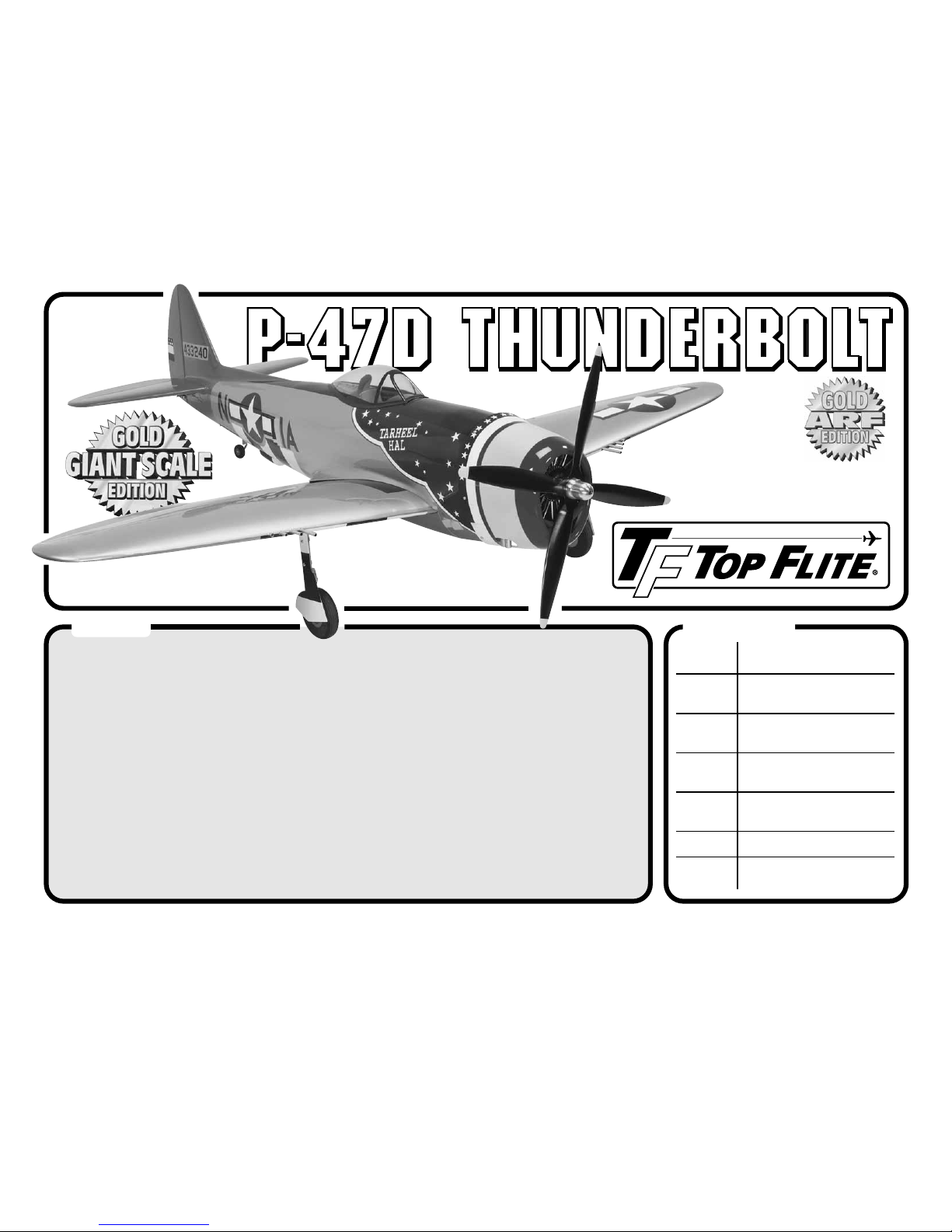
Top Flight Models P-47D Thunderbold User manual
READ THROUGH THIS MANUAL BEFORE STARTING CONSTRUCTION. IT CONTAINS IMPORTANT INSTRUCTIONS AND WARNINGS CONCERNING THE ASSEMBLY AND USE OF THIS MODEL.
Entire Contents © Copyright 2009 TOPA0703 MnlV1.0
WARRANTY
Top Flite Models guarantees this kit to be free from defects in both material and workmanship at the date of
purchase.This warranty does not cover any component parts damaged by use or modification. In no case
shall Top Flite’s liability exceed the original cost of the purchased kit. Further, Top Flite reserves the
right to change or modify this warranty without notice.
In that Top Flite has no control over the final assembly or material used for final assembly, no liability shall be
assumed nor accepted for any damage resulting from the use by the user of the final user-assembled prod-
uct. By the act of using the user-assembled product, the user accepts all resulting liability.
If the buyer is not prepared to accept the liability associated with the use of this product, the buyer is
advised to return this kit immediately in new and unused condition to the place of purchase.
To make a warranty claim send the
defective part or item to Hobby
Services at this address:
Include a letter stating your name, return shipping address, as much contact information as possible (daytime
telephone number, fax number, e-mail address), a detailed description of the problem and a photocopy of the
purchase receipt. Upon receipt of the package the problem will be evaluated as quickly as possible.
Hobby Services
3002 N. Apollo Dr.Suite 1
Champaign IL 61822 USA
SPECIFICATIONS
™
Wingspan
:85 in
[2160mm]
Wing
Area: 1329 sq in
[85.7 dm2]
Weight: 19.5 – 21.5 lb
[8842–9749 g]
Wing
Loading: 34–37 oz/sq ft
[104–113 g/dm2]
Length: 75 in
[1905mm]
Radio: 5-7 channel
Engine: 2.6–4.0 cu in
[43–65cc] spark ignition gas
Top Flite Models Champaign, IL
Telephone (217) 398-8970, Ext. 5

2
INTRODUCTION
The P-47D has been recognized as an excellent
modeling subject. The large wing and tail area and
long tail moment make an ideal flying airplane –
especially for a warbird! The Top Flite Giant P-47
Kit is a very successful model. Now, Top Flite has
developed the Giant P-47D ARF following the same
design as the kit.The Giant P-47D ARF will get you in
the air quickly with a great looking model, without the
sanding and covering required to build a kit.
Forthelatesttechnicalupdates or manualcorrections
to the Giant P-47D ARF visit the Top Flite web site
at www.top-flite.com. Open the “Airplanes” link, then
select the Giant P-47D ARF.If there is new technical
information or changes to this model a “tech notice”
box will appear in the upper left corner of the page.
AMA
If you are not already a member of the AMA, please
join! The AMA is the governing body of model
aviation and membership provides liability insurance
coverage, protects modelers’rights and interests and
is required to fly at most R/C sites.
Academy of Model Aeronautics
5151 East Memorial Drive
Muncie, IN 47302-9252
Ph. (800) 435-9262 Or via the Internet at:
Fax (765) 741-0057 http://www.modelaircraft.org
IMPORTANT!!! Two of the most important things
you can do to preserve the radio controlled aircraft
hobby are to avoid flying near full-scale aircraft and
avoid flying near or over groups of people.
IMAA
The Top Flite Giant P-47D ARF is an excellent sport-
scale model and is eligible to fly in IMAA events.The
IMAA (International Miniature Aircraft Association) is
an organization that promotes non-competitive flying
INTRODUCTION . . . . . . . . . . . . . . . . . . . . . . . . . 2
AMA. . . . . . . . . . . . . . . . . . . . . . . . . . . . . . . . 2
IMAA . . . . . . . . . . . . . . . . . . . . . . . . . . . . . . . 2
SCALE COMPETITION . . . . . . . . . . . . . . . . . . . . 3
SAFETY PRECAUTIONS. . . . . . . . . . . . . . . . . . . 3
DECISIONSYOU MUST MAKE. . . . . . . . . . . . . . 3
Engine Recommendations. . . . . . . . . . . . . . . 3
Radio Equipment . . . . . . . . . . . . . . . . . . . . . . 4
Retractable Landing Gear . . . . . . . . . . . . . . . 4
ADDITIONAL ITEMS REQUIRED . . . . . . . . . . . . 5
Required Hardware and Accessories . . . . . . 5
Adhesives and Building Supplies. . . . . . . . . . 5
Optional Supplies and Tools. . . . . . . . . . . . . . 5
IMPORTANT BUILDING NOTES . . . . . . . . . . . . . 5
KIT INSPECTION. . . . . . . . . . . . . . . . . . . . . . . . . 6
ORDERING REPLACEMENT PARTS . . . . . . . . . 6
COMMON ABBREVIATIONS. . . . . . . . . . . . . . . . 6
KIT CONTENTS. . . . . . . . . . . . . . . . . . . . . . . . . . 7
ASSEMBLE THE WINGS. . . . . . . . . . . . . . . . . . . 7
Hinge the Ailerons . . . . . . . . . . . . . . . . . . . . . 7
Mount the Aileron Servos. . . . . . . . . . . . . . . . 8
Mount the Retracts. . . . . . . . . . . . . . . . . . . . . 9
Install the Flap Servos . . . . . . . . . . . . . . . . . 11
Install the Aileron and Flap Pushrods . . . . . 11
Join the Wing . . . . . . . . . . . . . . . . . . . . . . . . 12
INSTALL THE FIXED MAIN LANDING GEAR . . 13
ASSEMBLE THE FUSELAGE . . . . . . . . . . . . . . 14
Install the Stabilizer . . . . . . . . . . . . . . . . . . . 14
Mount the FixedTail Gear . . . . . . . . . . . . . . 16
Mount the RetractableTail Gear. . . . . . . . . . 16
Install the Elevator and Rudder Servos . . . . 18
INSTALL THE ENGINE. . . . . . . . . . . . . . . . . . . . 19
ASSEMBLE AND INSTALL THE FUELTANK . . 21
INSTALL THE AIR RETRACT CONTROLS . . . . 22
INSTALL THE COWL . . . . . . . . . . . . . . . . . . . . . 23
APPLYTHE FINAL DETAILS . . . . . . . . . . . . . . . 26
FINISH THE WING. . . . . . . . . . . . . . . . . . . . . . . 28
Apply the Decals . . . . . . . . . . . . . . . . . . . . . 29
GET THE MODEL READY TO FLY . . . . . . . . . . 30
Install the Propeller . . . . . . . . . . . . . . . . . . . 30
Balance the Model Laterally. . . . . . . . . . . . . 30
Check the Control Directions. . . . . . . . . . . . 30
Set the Control Throws. . . . . . . . . . . . . . . . . 30
Balance the Model (C.G.). . . . . . . . . . . . . . . 31
CHECK LIST . . . . . . . . . . . . . . . . . . . . . . . . . . . 32
PREFLIGHT . . . . . . . . . . . . . . . . . . . . . . . . . . . . 33
IdentifyYour Model. . . . . . . . . . . . . . . . . . . . 33
Charge the Batteries . . . . . . . . . . . . . . . . . . 33
Ground Check and Range Check . . . . . . . . 33
ENGINE SAFETY PRECAUTIONS . . . . . . . . . . 33
AMA SAFETY CODE . . . . . . . . . . . . . . . . . . . . . 33
General . . . . . . . . . . . . . . . . . . . . . . . . . . . . 34
Radio Control. . . . . . . . . . . . . . . . . . . . . . . . 34
IMAA SAFETY CODE . . . . . . . . . . . . . . . . . . . . 34
FLYING. . . . . . . . . . . . . . . . . . . . . . . . . . . . . . . . 35
Fuel Mixture Adjustments . . . . . . . . . . . . . . 35
Takeoff . . . . . . . . . . . . . . . . . . . . . . . . . . . . . 35
Flight . . . . . . . . . . . . . . . . . . . . . . . . . . . . . . 35
Landing . . . . . . . . . . . . . . . . . . . . . . . . . . . . 36
GEAR DOOR DRILL GUIDE . . . . . . . . . . . . . . . 36
TABLE OF CONTENTS
2
l
e
T
a
il
G
ea
r
..........
16
n
d Rudder
S
ervo
s
. . . .
18
3
of giant-scale models. If you plan to attend an IMAA
event, obtain a copy of the IMAA Safety Code by
contacting the IMAA at the address or telephone
number below.
IMAA
205 S.Hilldale Road
Salina, KS 67401
Ph. (913) 823-5569Or via the Internet at:
www.fly-imaa.org/
imaa/sanction.html
SCALE COMPETITION
Though the Top Flite Giant P-47D is an ARF and
may not have the same level of detail as an “all-out”
scratch-built competition model, it is a scale model
nonetheless and is therefore eligible to compete in
the Fun Scale class in AMA competition (we receive
many favorable reports of Top Flite ARFs in scale
competition!).In Fun Scale, the“builder of the model”
rule does not apply.To receive the five points for scale
documentation, the only proof required that a full size
aircraft of this type in this paint/markings scheme
did exist is a single sheet such as a kit box cover
from a plastic model, a photo, or a profile painting,
etc. If the photo is in black and white, other written
documentation of color must be provided. Contact
the AMA for a rule book with full details.
If you would like photos of the full-size Tarheel Hal
P-47D for scale documentation, or if you would like
to study the photos to add more scale details, photo
packs are available from:
Bob’s Aircraft Documentation
3114Yukon Ave
Costa Mesa, CA 92626
Ph: (714) 979-8058 Or via the Internet at:
Fax: (714) 979-7279www.bobsairdoc.com
PROTECTYOUR MODEL,
YOURSELF & OTHERS…
FOLLOWTHESE IMPORTANT
SAFETY PRECAUTIONS
1. Your Giant P-47D ARF should not be considered
a toy, but rather a sophisticated, working model that
functions very much like a full-size airplane.Because
of its performance capabilities, the Giant P-47D
ARF, if not assembled and operated correctly, could
possibly cause injury to yourself or spectators and
damage to property.
2. You must assemble the model according to the
instructions. Do not alter or modify the model, as
doing so may result in an unsafe or unflyable model.
In a few cases the instructions may differ slightly from
the photos.In those instances the written instructions
should be considered as correct.
3. You must take time to build straight, true and
strong.
4. You must use an R/C radio system that is in
good condition, a correctly sized engine, and other
components as specified in this instruction manual.
All components must be correctly installed so that the
model operates correctly on the ground and in the air.
You must check the operation of the model and all
components before every flight.
5. If you are not an experienced pilot or have not
flown this type of model before, we recommend that
you get the assistance of an experienced pilot in your
R/C club for your first flights. If you’re not a member
of a club, your local hobby shop has information
about clubs in your area whose membership includes
experienced pilots.
6. While this kit has been flight tested to exceed
normal use, if the plane will be used for extremely
high stress flying, such as racing, or if an engine
larger than one in the recommended range is used,
themodelerisresponsiblefortakingstepstoreinforce
the high stress points and/or substituting hardware
more suitable for the increased stress.
7. WARNING: The cowl and landing gear covers
included in this kit are made of fiberglass, the fibers
of which may cause eye, skin and respiratory tract
irritation. Never blow into a part to remove fiberglass
dust, as the dust will blow back into your eyes.Always
wear safety goggles, a particle mask and rubber
gloves when grinding, drilling and sanding fiberglass
parts.Vacuum the parts andthe work areathoroughly
after working with fiberglass parts.
We, as the kit manufacturer, provide you with a top
quality, thoroughly tested kit and instructions, but
ultimately the quality and flyability of your finished
model depends on how you build it; therefore, we
cannot in any way guarantee the performance of
your completed model, and no representations
are expressed or implied as to the performance or
safety of your completed model.
REMEMBER: Take your time and follow the
instructions to end up with a well-built model that is
straight and true.
DECISIONSYOU MUST MAKE
This is a partial list of items required to finish the
Giant P-47D ARF that may require planning or
decision making before starting to build. Order
numbers are provided in parentheses.
ENGINE RECOMMENDATIONS
When considering engines for this model, refer to
the engine size recommendations on the cover of
the manual. Spark-ignition “gas” engines are most
popular with large-scale warbirds such as this. One
advantageofagasengineiseconomy– gasengines
tend to consume less fuel than a glow engine as
well. Additionally, gas engines deposit little exhaust
residue on the model. Among other engines, this
model was test flown with a Fuji-Imvac BT-43EI-2
engine. The Fuji-Imvac BT-43EI-2 provides more
than adequate power and flies the Giant P-47D ARF
in a scale-like manner.

4
NOTE: Instructions for mounting every possible
engine cannot be incorporated into this manual.
Modelers using another engine may refer to the
instructions as a guide for mounting their engine in a
similar way. If using the BT-43EI-2 engine an optional
muffler is recommended.
❏Bisson Inverted Muffler (BISG6543)
Per the IMAA Safety Code, magneto spark-ignition
engines must have a coil-grounding switch on the
aircraft to stop the engine and prevent accidental
starting, The switch must be operated manually
(without the use of the transmitter) and accessible by
thepilotandassistant.Ifusingaspark-ignitionengine,
refer to Install the Cowl on page 25 for details.
RADIO EQUIPMENT
Theradioequipmentandnumberofchannelsrequired
to fly the Top Flite Giant P-47D ARF depends on the
capabilities of your transmitter and how the servos
will be connected.
The Giant P-47D ARF requires a servo to operate the
air control valve if using retracts, a throttle servo, two
flap servos, two aileron servos, two elevator servos
and a rudder servo. Servos with a minimum of 50 oz-
in [3.9kg-cm] of torque are required for operating the
elevators, rudder, ailerons and flaps.We recommend
that metal geared servos also be used. Standard
servos may be used for the throttle and choke (the
servo operated choke is optional). A micro servo is
required to operate the retract air valve. An optional
servo operated kill switch may also be used (this is
in addition to the IMAA-required, manually operated
engine kill switch.A servo operated kill switch is only
really necessary for engines that do not reliably shut
off by closing the carburetor, but could also serve as
a backup.
Function Type RequiredQty.
Elevators 2 Futaba
S3305 (FUTM0045)
min. 50 oz-in torque
Rudder 1 Futaba
S3305 (FUTM0045)
min. 50 oz-in torque
Ailerons 2 Futaba
S3305 (FUTM0045)
min. 50 oz-in torque
Flaps 2 Futaba
S3305 (FUTM0045)
min. 50 oz-in torque
Tail
Steering 1Futaba
S3305 (FUTM0045)
min. 50 oz-in torque
Throttle 1 Futaba
S3004 (FUTM0027)
standard
Retract 1 Futaba
S3102 (FUTM0034)
micro
Optional
Choke Futaba
S3004 (FUTM0027)
standard
1
Total10–11
A receiver battery with a minimum of 1,000mAh is
recommended for flying the Giant P-47D ARF. The
battery voltage should be checked before every flight
to be certain it has enough “charge”.
In addition to the servos, the following items (or
similar items) are also required. The order numbers
shown in parentheses are for Futaba servos.
Items RequiredQty.
46"Y-harness for elevator, rudder/steering,
ailerons & flaps (FUTM4130)
46" Servo Extension for throttle, optional
choke, ailerons & flaps (HCAM2701)
312" [305mm] Servo Extension
for flaps & receiver switch (HCAM2711)
224" [610mm] Servo Extension
for ailerons (HCAM27021)
2Heavy Duty Switch Harness (FUTM4385)
1Ernst Charge Receptacle 124 (ERNM3001)
Note: The length and quantity of servo extensions
and Y-connectors may vary depending on the brand
of radio you are using and the radio installation.
RETRACTABLE LANDING GEAR
The Top Flite Giant P-47D ARF may be assembled
with either the included fixed landing gear or optional
retractable landing gear. If fixed landing gear is used
no other items will need to be purchased to install the
gear. If you wish to install retractable landing gear,
this model is designed for Robart pneumatic retracts.
Following is the complete list of items required to
install the Robart retracts:
Items RequiredQty.
1Robart #622P47
Top Flite Giant P-47
Pneumatic Retractable Main Landing Gear
(ROBQ1637)
1Robart #160LWC
RetractableTail Gear Assembly
(ROBQ2225)
1
Robart #157VRX
Large-Scale Deluxe Air Control Kit
– includes pressure tank, air line tubing,
variable-rate air valve, T-fittings
(ROBQ2305)
1Robart #169
10' [3048mm] Red & Purple Pressure Tubing
(ROBQ2369)
1
pkg. Robart #190
Air Line Quick Disconnects
(ROBQ2395)
Note: An air pump will also be required to pressurize
the air tank. The Robart hand pump could be used,
but is not practical because of the large capacity
of the air tank in this model. A small, 12V electric
pump is recommended and can be purchased at an
automotive or hardware store.

5
ADDITIONAL ITEMS REQUIRED
REQUIRED HARDWARE AND
ACCESSORIES
In addition to the items listed in the “Decisions You
Must Make” section, following is the list of hardware
and accessories required to finish the Top Flite
Giant P-47D ARF. Order numbers are provided in
parentheses.
❏(2) Dubro #813 1/8" Fuel Line Barb (DUBQ0670)
❏(1) Dubro #554 X-large Tygon Fuel Line
(DUBQ0427)
❏(1) R/C foam rubber (1/4" [6mm] (HCAQ1000) or
1/2" [13mm] (HCAQ1050)
❏Optional Black paint for the plywood radial
engine frame
❏Propeller and spare propellers suitable for your
engine.
❏Painted Pilot (GPMA2807)
ADHESIVES AND BUILDING SUPPLIES
This is the list of Adhesives and Building Supplies
that are required to finish the Giant P-47D ARF.
❏1/2 oz. [15g] Thin Pro™CA (GPMR6001)
❏1/2 oz. [15g] Medium Pro CA+ (GPMR6007)
❏Pro 30-minute epoxy (GPMR6047)
❏Pro 6-minute epoxy (GPMR6045)
❏Threadlocker thread locking cement
(GPMR6060)
❏Mixing sticks (50, GPMR8055)
❏Mixing cups (GPMR8056)
❏Epoxy brushes (6, GPMR8060)
❏Denatured alcohol (for epoxy clean up)
❏R/C-56 canopy glue (JOZR5007)
❏Milled fiberglass (GPMR6165)
❏Masking tape (TOPR8018)
❏Plan protector (GPMR6167) or wax paper
❏Drill bits: 1/16" [1.6mm], 5/64" [2mm], 3/32"
[2.4mm], 7/64" [2.8mm], 1/8" [3.2mm], 3/16"
[4.8mm], 1/4" [6.4mm]
❏Small metal file
❏Stick-on segmented lead weights (GPMQ4485)
❏Silver solder w/flux (STAR2000)
❏Hobby Heat™micro torch (HCAR0755)#1 Hobby
knife (HCAR0105)
❏#11 blades (5-pack, HCAR0211)
❏#11 blades (100-pack, HCAR0311)
❏Sanding tools and sandpaper assortment (see
Easy-Touch™Bar Sander section)
❏Curved-tip canopy scissors for trimming plastic
parts (HCAR0667)
Covering tools
❏Top Flite MonoKote®sealing iron (TOPR2100)
❏Top Flite Hot Sock™iron cover (TOPR2175)
❏Top Flite MonoKote trim seal iron (TOPR2200)
❏Top Flite MonoKote heat gun (TOPR2000)
OPTIONAL SUPPLIES ANDTOOLS
Hereisa list ofoptionaltoolsmentionedinthe manual
that will help you build the Giant P-47D ARF.
❏2 oz. [57g] spray CA activator (GPMR6035)
❏CA applicator tips (HCAR3780)
❏CA debonder (GPMR6039)
❏Builder’s Triangle Set (HCAR0480)
❏Scale Warbird Template (TOPQ2187)
❏36" metal ruler (HCAR0475)
❏Hobbico®High Precision Diagonal Cutter 5"
(HCAR0630)
❏Pliers with wire cutter (HCAR0625)
❏Robart Super Stand II (ROBP1402)
❏Switch & Charge Jack Mounting Set
(GPMM1000)
❏Panel Line Pen (TOPQ2510)
❏Rotary tool such as Dremel
❏Rotary tool reinforced cut-off wheel (GPMR8200)
❏Servo horn drill (HCAR0698)
❏AccuThrow™Deflection Gauge (GPMR2405)
❏CG Machine™ (GPMR2400)
❏Laser incidence meter (GPMR4020)
❏36" bar for incidence meter (GPMR4021)
❏Precision Magnetic Prop Balancer (TOPQ5700)
IMPORTANT BUILDING NOTES
●Anytime a sheet metal screw is installed in wood,
first install the screw, remove the screw and apply a
couple of drops of thin CA in the hole to harden the
threads.After the CA has cured, reinstall the screw.
●Photos and sketches are placed before the
step they refer to. Frequently you can study photos in
following steps to get another view of the same parts.
●The Giant P-47D ARF is factory-covered with Top
Flite MonoKote film. Should repairs ever be required,
MonoKote can be patched with additional MonoKote
purchased separately. MonoKote is packaged in six-
foot rolls, but some hobby shops also sell it by the
foot. If only a small piece of MonoKote is needed for
a minor patch, perhaps a fellow modeler would give
you some.MonoKote is applied with a model airplane
coveringiron,butinanemergencyaregularironcould
be used. A roll of MonoKote includes full instructions
for application. Following are the colors used on this
model and order numbers for six foot rolls.
Aluminum (TOPQ0205)
Orange (TOPQ0202)
White (TOPQ0204)
Black (TOPQ0208)
Sapphire Blue (TOPQ0226)
Missile Red (TOPQ0201)

6
●The stabilizer and wing incidences and engine
thrust angles have been factory-built into this
model. However, some technically-minded modelers
may wish to check these measurements anyway.
To view this information visit the web site at www.
greatplanes.com and click on “Technical Data.” Due
to manufacturing tolerances which will have little
or no effect on the way your model will fly, please
expect slight deviations between your model and the
published values.
KIT INSPECTION
Before starting to build, take an inventory of this kit
to make sure it is complete, and inspect the parts
to make sure they are of acceptable quality. If any
parts are missing or are not of acceptable quality, or if
you need assistance with assembly, contact Product
Support. When reporting defective or missing parts,
use the part names exactly as they are written in the
Kit Contents list.
Top Flite Product Support
3002 N Apollo Drive, Suite 1
Champaign, IL 61822
Ph: (217) 398-8970, ext. 5
Fax: (217) 398-7721
E-mail: airsupport@top-flite.com
ORDERING
REPLACEMENT PARTS
ReplacementpartsfortheTopFliteGiantP-47DARFare
availableusingtheordernumbersinthe Replacement
Parts List that follows. The fastest, most economical
service can be provided by your hobby dealer or mail-
order company. Not all parts are available separately
(an aileron cannot be purchased separately, but is only
available with the wing kit).Replacement parts are not
available from Product Support, but can be purchased
from hobby shops or mail order/Internet order firms.
Hardware items (screws, nuts, bolts) are also available
from these outlets.
To locate a hobby dealer, visit www.top-flite.com
and click on “Where to Buy”. Follow the instructions
provided on the page to locate a U.S., Canadian or
International dealer.
Parts may also be ordered directly from Hobby
Services by calling (217) 398-0007, or via facsimile
at (217) 398-7721, but full retail prices and shipping
and handling charges will apply. Illinois and Nevada
residents will also be charged sales tax. If ordering
via fax, include a Visa or MasterCard number and
expiration date for payment.
Mail parts orders Hobby Services
and payments by 3002 N Apollo Drive, Suite 1
personal check to: Champaign IL 61822
Be certain to specify the order number exactly as
listed in the Replacement Parts List. Payment by
credit card or personal check only;no C.O.D.
If additional assistance is required for any reason
contactProductSupportbye-mailatproductsupport@
top-flite.com, or by telephone at (217) 398-8970.
Order
Number Description
REPLACEMENT PARTS LIST
How to
purchase
Instruction manual
Missing pieces
Full-size plans
FuselageTOPA1810
Wing SetTOPA1811
Stab/ElevatorsTOPA1812
RudderTOPA1813
CowlTOPA1814
CanopyTOPA1815
Landing Gear Wires
TOPA1816
Contact
Product
Support
Not available
Contact
your
hobby
supplier
to
purchase
these
items
Order
Number Description How to
purchase
Gear CoversTOPA1817
Dummy EngineTOPA1818
Tailwheel Assy.TOPA1819
Spinner HubTOPA1820
DecalsTOPA1821
Stab TubesTOPA1822
Contact
your
hobby
supplier
to
purchase
these
items
COMMON ABBREVIATIONS
Stab = Horizontal Stabilizer
Fin = Vertical Stabilizer
LE = Leading Edge
TE = Trailing Edge
" = Inches
mm = Millimeters
SHCS = Socket Head Cap Screw
mAh = Milliamp Hours (refers to the
usable capacity of a battery)
To convert inches to millimeters, multiply inches
by 25.4 (25.4mm = 1")
7
ASSEMBLETHEWINGS
HINGETHE AILERONS
Start with the left wing so the assembly matches the
photos the first time through.
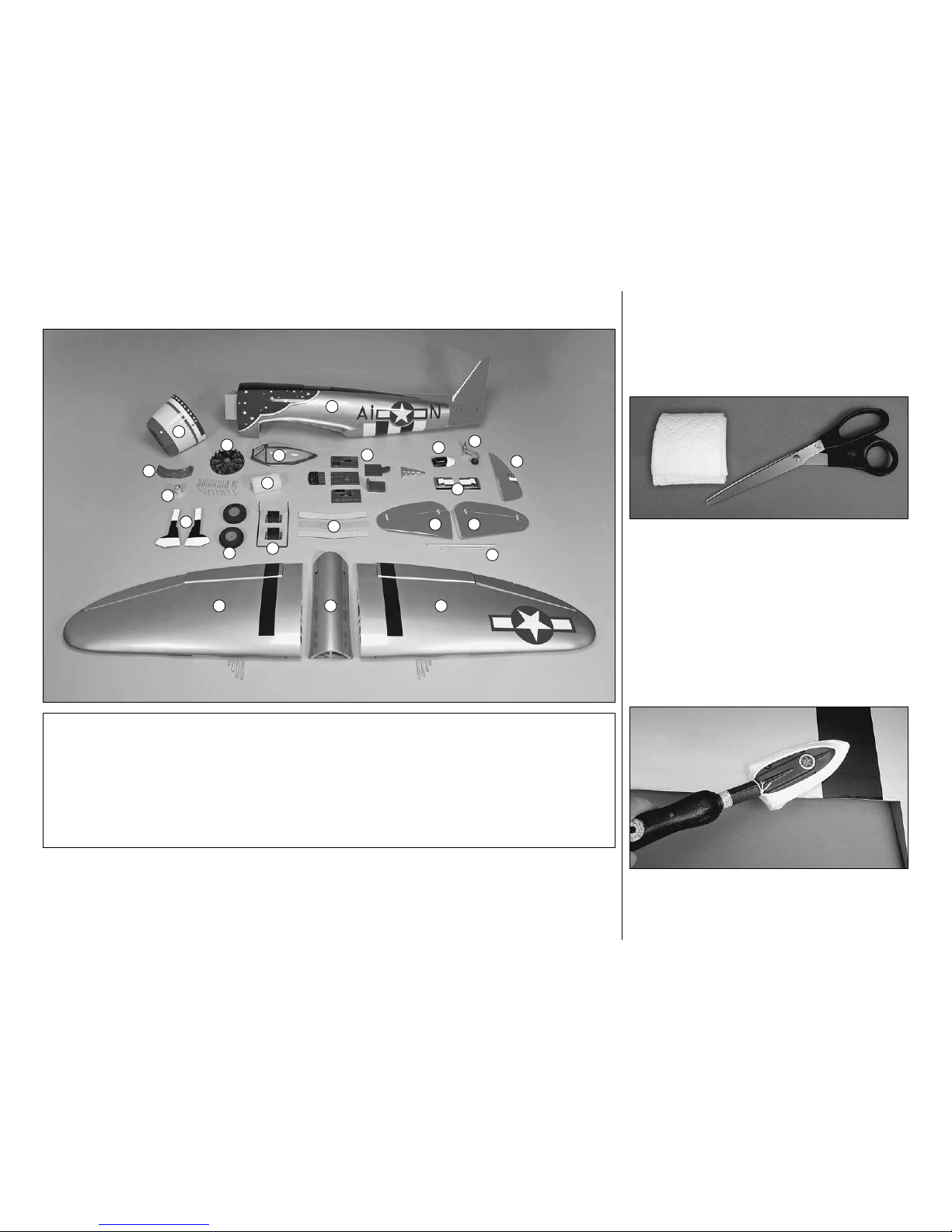
❏1. Lay a few paper towels on top of each other
and cut them into small squares.These paper towel
squares will come in handy for wiping away excess
epoxy throughout the assembly process (and will
save you from wasting whole paper towels).
❏❏2. Separate the aileron and flap from the wing
by carefully peeling off the masking tape holding
them together. Use a paper towel square dampened
with naphtha lighter fluid or similar solvent to remove
any glue left behind from the tape.
❏❏3. If necessary, use a covering iron with a
covering sock to go over the wing, flap and aileron
to remove any wrinkles. The best method to remove
the wrinkles is to glide the iron over the covering until
KIT CONTENTS
1 - Fuselage
2 - Left wing
3 - Right wing
4 - Belly pan
5 - Left Stabilizer
6 - Right Stabilizer
7 - Stabilizer Joiner Tubes
8 - Rudder
9- Fixed Tail Gear
10 - Innercooler Exhausts
11 - Turbo Charger Exhaust
12 - Cockpit Parts
13 - Wing Joiner Parts
14 - Fixed Main Gear
15 - Wheels
16 - Landing Gear Doors
17 - Fuel Tank
18 - Canopy
19- Dummy Engine
20 - Spinner Nut
21 - Cooler Intake
22 - Cowl
1
6
2
4
9
10
11
12
13
14
16
15
17
18
19
20
21
8
7
3
5
22
8
the wrinkles disappear, then go over the area again,
pushing down on the iron to bond the covering to the
wood. If the wrinkles don’t disappear, the balsa in
that area might be flexing inward.If this is happening,
don’tpress down.Simply lettheheatof theironshrink
the covering. If the wrinkles momentarily disappear,
then immediately reappear, the iron may be too hot,
thus causing air bubbles. Lower the temperature of
the iron or use a sharp #11 blade to puncture several
holes in the covering, then reheat. The suggested
iron temperature is around 360 degrees F.
The P-47 had many attributes that led to its
reputation. One of the most important was its
durability in combat. Oftentimes the P-47 would
bring pilots home with missing cylinders, blown-off
wingtips and largeportionsoftail surfaces missing.
The P-47’s internal systems were also durable and
well protected.
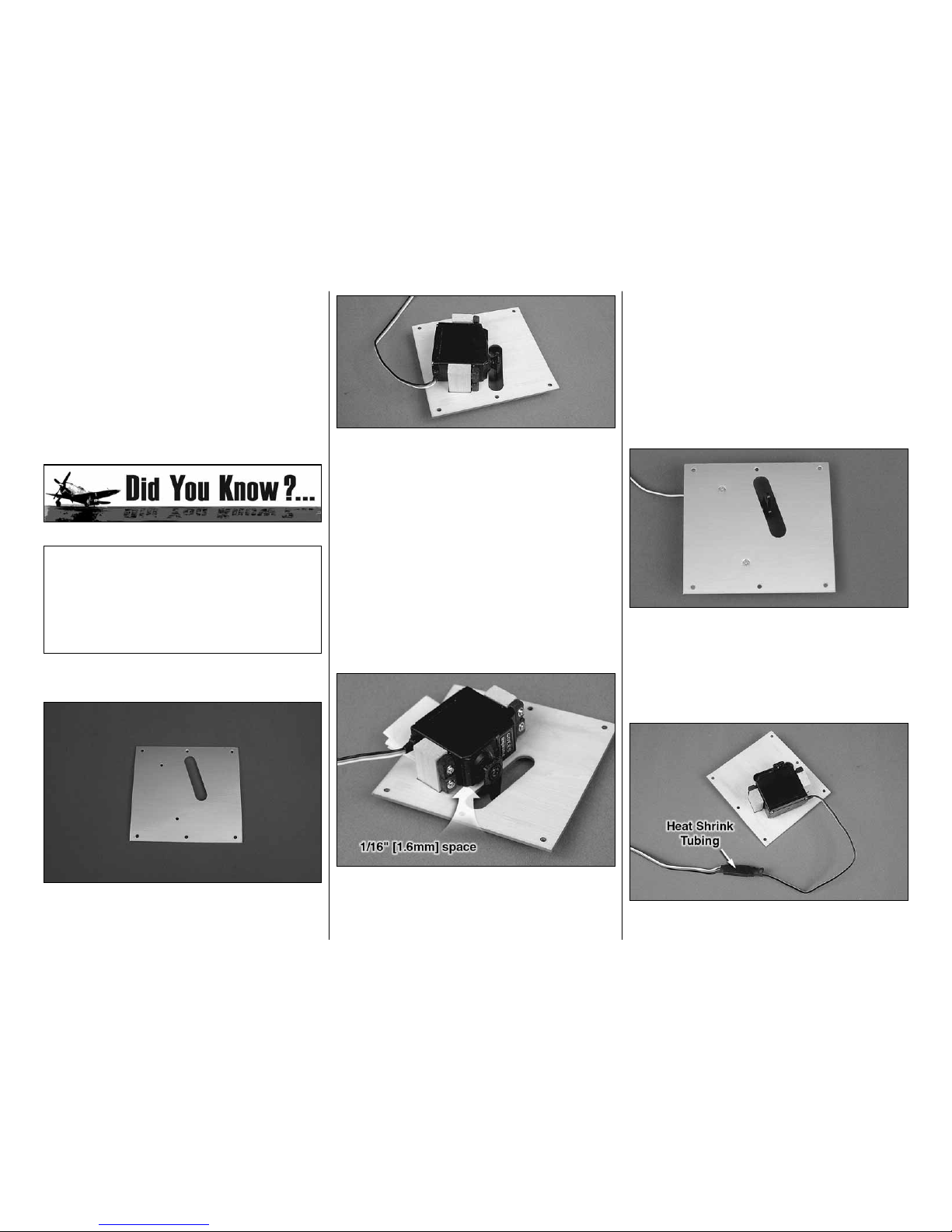
MOUNTTHE AILERON SERVOS
❏❏1. Use a sharp hobby knife to trim the opening
from over the left aileron servo hatch and the eight
screw holes.
❏❏2. Install a servo arm on the aileron servo.
Position the aileron servo on the aileron servo hatch
cover as shown with the servo arm centered in the
opening.Set the two 5/16" x 5/8" x 13/16" [7.9x 15.8
x 20.6mm] hardwood blocks in the embossed servo
block locations, checking that they are correct. If not,
mark the new location.
❏❏3. Use 6-minute epoxy to glue the two blocks
to the bottom of the servo hatch over the embossed
servo block locations. Thoroughly coat the end of
the blocks and allow them to set for a few seconds
while the blocks absorb the epoxy. Then, recoat the
blocks. Use clamps to hold the blocks to the servo
hatch tray.
❏❏4. Once the epoxy has cured, remove the
clamps.Place a1/16"[1.6mm]spacer,suchas a piece
of cardstock or a piece of paper folded several times,
under the servo and between each mounting block.
After the servo is installed the spacer will be removed,
providing adequate spacing for vibration isolation.
❏❏5. Drill 1/16" [1.6mm] holes through the blocks
for the servo mounting screws. Mount the servo to
the blocks with the screws that came with the servo.
Remove the servo mounting screws and apply a
couple of drops of thin CA in each hole to harden the
threads. Allow the CA to fully harden.Then, reinstall
the servos and remove the spacer.
❏❏6. Drill 1/16" [1.6mm] holes through the blocks
at the two hole locations on the top of the aileron
servo hatch. Install two #2 x 3/8" [9.5mm] flat head
sheet metal screws to secure the servo mounting
blocks to the aileron servo hatch. Use thin CA to
harden the screw threads
❏❏7.Connect a 24" [610mm] servo extension wire
to the aileron servo. Cut a piece of heat shrink tubing

9
in half and slide it over the servo connections. Shrink
the tubing by applying heat to the tubing.
❏❏8. Use the string in the wing to pull the aileron
wire through the wing.
❏❏9. Place the aileron servo hatch with the servo
in the wing. Be certain that the hatch is positioned
correctly as shown. Secure the hatches using six #2
x 3/8" [9.5mm] flat head sheet metal screws.Use thin
CA to harden the screw threads.
❏10. Go back to step 1 and install the right aileron
servo following the same procedure.
MOUNTTHE RETRACTS
Note: The fixed main landing gear will not be
installed until after the two wing halves have been
joined.If usingthefixedmainlanding gear, proceed
to “Install the Flap Servos” on page 13.
Install the left retract first.
❏❏1. Use a hex wrench to loosen the strut
mounting bolt and remove the strut. Slide two
aluminum landing gear door mounts onto the strut
and reinstall the strut in the strut mount.
❏❏2.Trim the axle that is included with the Robart
retracts to 1-1/2" [38mm] long. File a flat spot at the
end of the axle. Insert the axle through the included
5" [127mm] wheel and into the retract.Apply a drop of
threadlocker to the 10-32 x 3/16" [4.8mm] set screw,
included with the retract, and tighten the set screw
onto the flat of the axle. Make sure that the wheel
rotates freely.
❏❏3.Test fit the retract unit with the wheel into the
wing. Position the retract so the wheel is centered in
the wheel well. Adjust the strut position in the retract
body as necessary to achieve the correct spacing
all the way around the wheel.You may need to sand
the top of the opening in the rib slightly to allow the
retract to fit.Remove as little wood as possible.
10
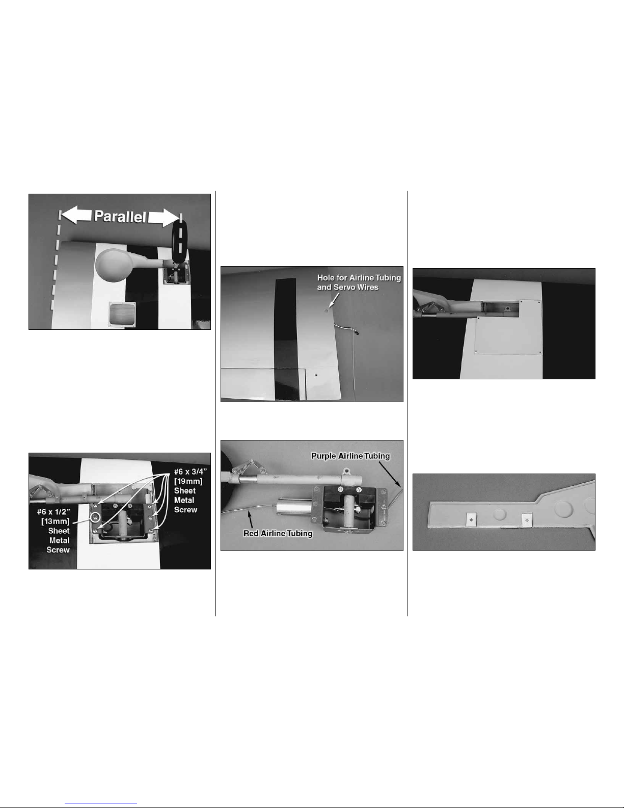
❏❏4. Extend the retract. View the wheel from
directly above. Adjust the strut so that the wheel
is parallel to the root of the wing. Lock the strut in
position by applying a drop of threadlocker to the
threads and securely tightening the bolt at the top of
the strut.
❏❏5. Double check that the wheel will fully retract
into the wing. Extend the retract to make sure it does
not interfere with any part of the wing and that the
retract is operating smoothly.
❏❏6.Holdtheretractinthewing.Usingthemounting
holes as a guide, drill 7/64" [2.8mm] pilot holes into the
retract rails.Caution: Do not inadvertently drill into the
air cylinder when you get to the middle hole. Mount
the retracts with five #6 x 3/4" [19.1mm] sheet metal
screws, one in each corner and one in the middle as
shown.Use one #6 x 1/2" [12.7mm] sheet metal screw
in the hole over the air cylinder.
❏❏7.Remove the six screws and retract and apply
a couple of drops of thin CA in the holes.
❏❏8. Cut the covering from the holes in the top of
the wing for the servo wires and the airline tubing.
❏❏9. Cut a 21" [533mm] piece of red air line
tubing and a 23" [584mm] piece of purple air line
tubing from the tubing included with the Robart Air
Control Kit (not included). Connect the red line to
the front of the air cylinder and the purple to the
back of the air cylinder.
❏❏10. Connect the two pieces of air line tubing to
the string in the retract bay. Guide the airline tubing
through the front of the retract bay, through the flap
bay and out the hole in the top of the wing. Also pull
the aileron servo lead out the hole. Tape the airline
andaileron servoleadtothe topofthewing.Remount
the retract in the wing.
❏❏11. Use a sharp hobby knife to remove the
covering from over the five mounting holes in the
plywood retract cover. Set the retract cover over the
retract and drill a 1/16" [1.6mm] pilot hole using the
holes in the cover as a guide.
❏❏12.Mount the retract cover to the wing with five
#2 x 3/8" [9.5mm] flat head sheet metal screws.
❏❏13.Cut two of the landing gear door drill guides
from the back of the manual. Place the drill guides
in the rectangle recesses of the landing gear door.
Place the landing gear door on a piece of scrap wood
and drill a 1/8" [3.2mm] hole through the door at the
marked hole location.
11
❏❏14. Adjust the position of the two landing gear
door mounts so that they align with the flats on the
landing gear door when the door is positioned in the
landing gear opening.
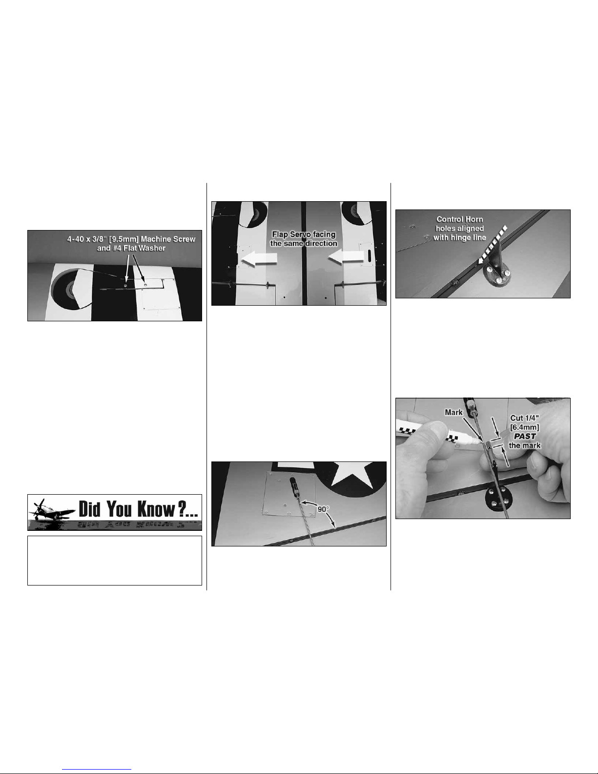
❏❏15. Install a #4 flat washer on 4-40 x 3/8"
[9.5mm] machine screw. Insert the machine screw
through one of the holes in the gear door and
thread it into the landing gear door mount.Note that
it tightens against the landing gear strut before it
tightens against the gear door. Install the second
machine screw to hold the gear door in position.
Check to make sure that the gear door is flush with
the bottom of the wing. 1.5mm thick rectangular
plywood spacers have been included to space the
gear doors out if needed. Both screws will need to
be shortened, a little at a time, so that they tighten
against both the landing gear strut and the gear
door. Be sure to use threadlocker on the screws.
❏16. Return to step 1 and mount the right retract in
the right wing.
The P-47 was manufactured by Republic Aircraft
Corporation, which at one time was named
Seversky Aircraft Corporation, started by two fellow
Russians, Alexander De Seversky and Alexander
Kartveli.
INSTALLTHE FLAP SERVOS
❏❏1. Install the flap servos following the same
procedure used to install the aileron servos.Note that
the flap servos face the same direction.
❏❏2.Connect a 12" [305mm] servo extension wire
to the flap servo. Secure the extension to the servo
with a piece of heat shrink or electrical tape.
❏❏3. Route the flap servo leads to the root of the
wing and out the hole in the top of the wing.
INSTALLTHE AILERON AND
FLAP PUSHRODS
Do the left aileron first.
❏❏1. Slide a silicone clevis retainer over a 4-40
threaded metal clevis.Thread a 4-40 nut followed by
the 4-40 metal clevis, threaded 12 turns onto a 4-40
x 12" [305mm] metal pushrod.Attach the clevis to the
aileron servo arm 5/8" [15.9mm] from the center of
the arm.
❏❏2. Position the control horn so that it is inline
with the pushrod and over the plywood mounting
plate. The pushrod holes in the control horn should
be aligned with the hinge line of the aileron. On the
aileron, mark the four mounting holes. Remove the
control horn and drill a 5/64" [2mm] pilot hole at each
mark. Do not drill completely through the aileron.
Attach the control horn using four #4 x 1/2" [12.7mm]
sheet metal screws. Use thin CA to harden the holes.
❏❏3. Install the metal solder clevis in the second
hole from the end of the control horn. Center the
aileron servo and aileron. Mark the pushrod where it
meets the solder clevis. Remove the pushrod and the
solder clevis and cut the pushrod 1/4" [6.4mm] past
the mark.Solder the solder clevis to the pushrod using
the techniques described in the following HotTip.
12
HOW TO SOLDER
1. Use denatured alcohol or other solvent to
thoroughly clean the pushrod. Roughen the end of
the pushrod with coarse sandpaper where it is to
be soldered.
2. Apply a few drops of soldering flux to the end of
the pushrod, then use a soldering iron or a torch
to heat it. “Tin” the heated area with silver solder
by applying the solder to the end.The heat of the
pushrod should melt the solder – not the flame
of the torch or soldering iron – thus allowing the
solder to flow.The end of the wire should be coated
with solder all the way around.
3. Place the clevis on the end of the pushrod. Add
another drop of flux, then heat and add solder.
The same as before, the heat of the parts being
soldered should melt the solder, thus allowing
it to flow. Allow the joint to cool naturally without
disturbing. Avoid excess blobs, but make certain
the joint is thoroughly soldered.The solder should
be shiny, not rough. If necessary, reheat the joint
and allow to cool.
4. Immediately after the solder has solidified, but
while it is still hot, use a cloth to quickly wipe off
the flux before it hardens.Important: After the joint
cools, coat the joint with oil to prevent rust. Note:
Do not use the acid flux that comes with silver
solder for electrical soldering.
This is what a properly soldered clevis looks
like – shiny solder with good flow, no blobs and
flux removed.
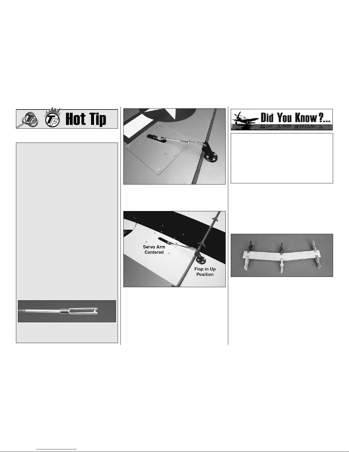
❏❏4.Slide a silicone clevis retainer over the solder
clevis.Reinstall the aileron pushrod with the threaded
clevis attached to the control horn.
❏❏5. Assemble and connect the flap pushrods
following the same procedure. We installed the
pushrod in the outer hole of the control horn and the
hole 3/8" [9.5mm] from the center of the servo arm.
Note: With the flap fully retracted “up”, the servo arm
is centered on the servo.
❏6. Return to step 1 and install the aileron and flap
pushrods on the right wing.
The Thunderbolt was a massive airplane, the
biggest and heaviest single engine, single-place
fighter ever built. The engine, the Pratt & Whitney
18 cylinder twin-row radial, developed 2,000 H.P.
and was the most powerful engine at the time.
However, in turn, it needed a highly efficient
duct system for its super-charger. The designer,
Alexander Kartvile, designed the duct system first,
then built the fuselage around it.
JOINTHE WING
Note: Keep the retracts (if installed) in the retracted
(up) position so they do not extend and retract as you
handle the wing.
❏1. Clean the aluminum wing joiner with denatured
alcohol to remove any possible contaminant.
❏2. Gather everything required for gluing the
wing joiner and wing together including 30-minute
epoxy, mixing sticks, epoxy brush, clamps, #64
rubberbands, 12" [305mm] long dowel or wire,
denatured alcohol and small paper towel squares.
Mix up a 1/2" oz. [14.7cc] of 30-minute epoxy. Apply
a generous amount of epoxy to one side of each of
the plywood wing joiners. Sandwich the aluminum
wing joiner between the two plywood wing joiners.
Hold the joiner together with clamps. Use a paper
towel dampened with denatured alcohol to wipe off
any excess epoxy around the edges.
13
❏3. Use 6-minute epoxy to glue the two 3/8"
[9.5mm] diameter forward wing dowels in the
leading edge of the wing. The wing dowels should
protrude approximately 1/2" [12.7mm] from the
wing. Also glue the 1/4" [6.4mm] aft root rib guide
dowel in the left wing half. Clean off any excess
epoxy before it cures.
❏4. Once the epoxy has cured, remove the clamps
from the wing joiner and sand off any excess epoxy
you may have missed.Test fit the wing joiner in each
wing half making sure that both wings halves fit
together at the root without any gap.Trial fit clamping
the wing together with rubberbands around the wing
dowels and the trailing edge.
❏5.Removetherubberbandsandseparatethewing
halves. Remove the wing joiner. Mix 2 oz. [59.1cc] of
30-minute epoxy. Working quickly, pour a generous
amount into the joiner pocket of one wing half. Use
your wire or dowel to thoroughly distribute the epoxy,
coating all surfaces inside the joiner pocket. Coat
the root rib and one half of the wing joiner that goes
into the wing. Insert the joiner in the wing. Proceed
immediately to the next step.
❏6.Coat the joiner pocket in the other wing half and
the other end of the wing joiner. Join the wing halves
together.Then, stand the wing on end with one of the
wing tips resting on the floor. Use a piece of R/C foam
or something similar to cushion and stabilize the wing
so it won’t slide around.
❏7. With the wing resting on end, use paper towel
squares to wipe off any excess epoxy as it squeezes
out. Wrap the rubberbands around the wing dowels
and the aft end of the wing. Add several strips of
masking tape to tightly hold the wings together as
you continue to wipe off excess epoxy as it squeezes
out. Be certain the leading and trailing edges of the
wing accurately align. Do not disturb the wing until
the epoxy has fully cured.
Perform this step only if you have installed retracts.
❏8. Join the matching air lines from each wing half
with a couple of T-fittings that came with the Robart
air control kit. Cut two 10" [254mm] pieces of air line
(also from the control kit) and fit each line to the
T-fittings.Connectonequick-connectorwithanO-ring
to one of the air lines and one of the quick connectors
without an O-ring to the other line. This will prevent
improper connection to the quick-connectors on the
air valve when mounting the wing to the fuselage.
INSTALLTHE FIXED MAIN
LANDING GEAR
If you have installed the retractable landing gear
proceed to ASSEMBLETHE FUSELAGE.
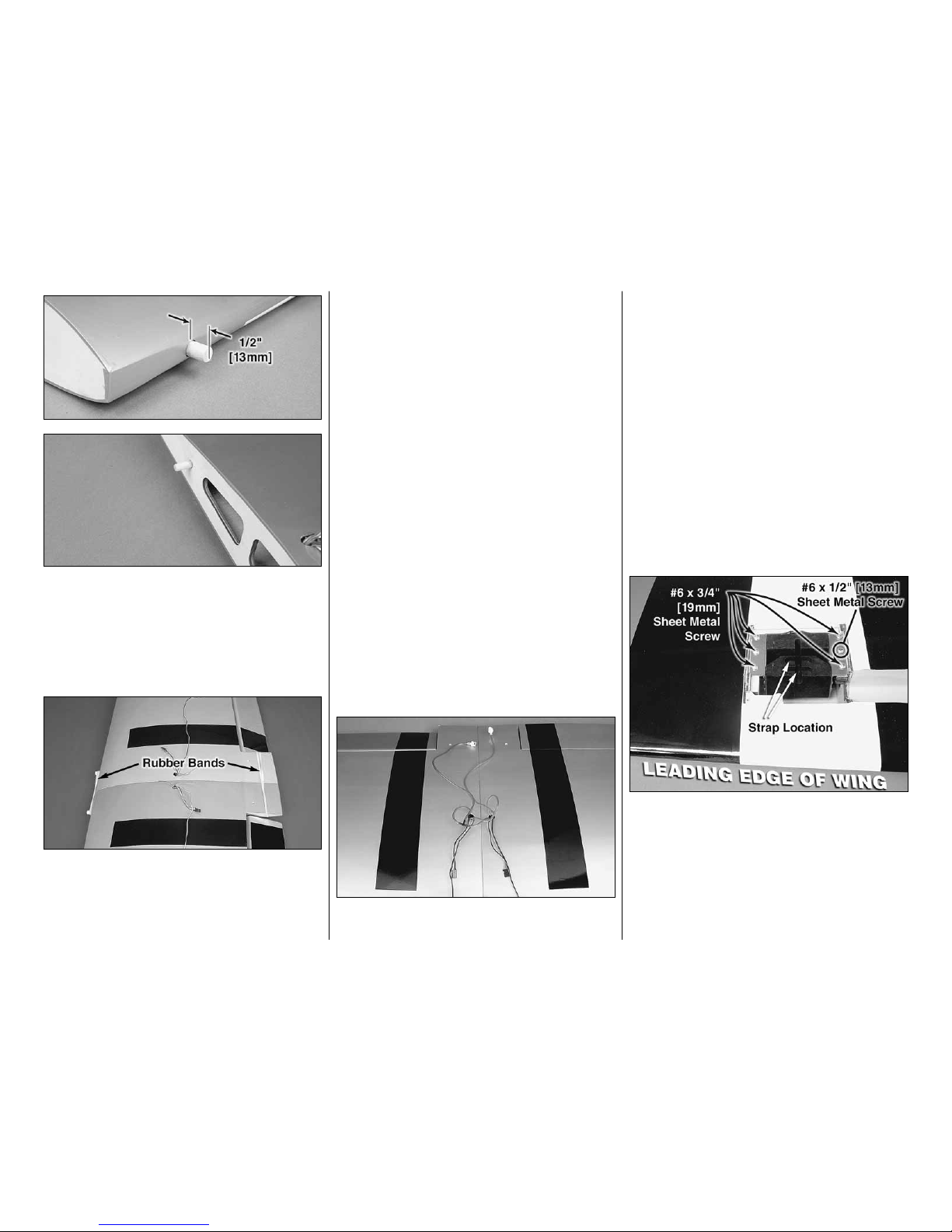
❏1. Place both fixed landing gear mounts on the
landing gear plates.The mounts are the same, but
the part with the straps goes towards the leading
edgeof thewing.Using the holesin the mountsasa
guide, drill six 7/64" [2.8mm] holes into the landing
gear plates. Attach the landing gear mounts to the
landing gear plates with five #6 x 3/4" [19.1mm]
sheet metal screws and one #6 x 1/2" [12.7mm]
sheet metal screw.

14
❏2. Mount each main landing gear wire in the
landing gear mount with two metal straps and four #4
x 1/2" [12.7mm] sheet metal screws.
❏3. Mount the wheels to the landing gear with
a wheel collar on both sides of both wheels. Use
a small drop of threadlocker on all the 3 x 5mm
machine screws.Make sure the machine screw in the
outer wheel collar tightens against the flat spot on the
landing gear wire.
❏4.Use a sharp hobby knife to remove the covering
from over the five mounting holes in the plywood
retract cover. Set the retract cover over the retract
and drill a 1/16" [1.6mm] pilot hole using the holes in
the cover as a guide.
❏5. Mount the retract cover to the wing with five #2
x 3/8" [9.5mm] flat head sheet metal screws.
Various prototypes and incarnations of the P-47
began to materialize at Republic Aircraft around
1940. One of the first designs recognizable as a
P-47 was the XP-44 Rocket. One of the engine
performance features carried over from Seversky
was the gear-driven supercharger and later a
turbo-supercharger.
ASSEMBLETHE FUSELAGE
INSTALLTHE STABILIZER
❏1. Test fit the two aluminum stabilizer tubes in the
fuselage and slide the stabilizers on the tubes. The
shorter tube goes in the front hole. If the aluminum
tubes are too tight to slide through the holes, take
a sharp hobby knife and gently scrape the inside of
the holes. During the manufacturing process a small
amount of resin or filler may be left behind in the hole.
❏2. Once you are satisfied with the fit of the
stabilizer halves, remove the stabilizer halves and
the joiner tubes. Use medium grit sandpaper to
roughen up the aluminum tubes.Clean the tubes with
denatured alcohol and insert both tubes back into the
fuselage until the end exits on the opposite side by
approximately 1" [25.4mm].
❏3. Gather everything required for gluing the
stabilizer halves to the fuselage, including 30-minute

15
epoxy, mixing sticks, epoxy brush, 12" [305mm] long
dowel or wire, masking tape, denatured alcohol and
small paper towel squares. Mix up 3/4 oz.[22.1cc] of
30-minute epoxy. Apply a generous amount of epoxy
to the long side of the aluminum joiner tubes. Pull
the tubes through the fuselage so that they are close
to centered. Pour a small amount of epoxy into both
holesof oneofthe stabilizer halves and usingadowel
or wire, coat the inside of the holes. Apply epoxy to
the root rib of the stabilizer and the fuselage. Insert
the end of the aluminum tubes with epoxy on them
into the stabilizer and press the stabilizer against
the fuselage. Wipe off any excess epoxy that may
have squeezed out before it runs down the fuselage.
Quickly repeat the process on the other side. Wipe
off any excess epoxy with a dampened paper towel
and denatured alcohol. Use pieces of masking tape
to hold the stabilizer tight against the fuselage until
the epoxy cures.
❏❏4. Without using any glue, install five hinges
into the rudder. Note that the pivot point of each
hinge must align with the center of the leading edge.
To achieve this alignment, the hinges will be fairly
deep in the rudder.Also note that the hinges must be
perpendicular to the leading edge.
❏❏5. Again without glue, test fit the rudder to
the fin. Move it left and right a few times to align the
hinges. The rudder doesn’t have to move very far,
only 2" [50.8mm] left and 2" [50.8mm] right measured
at the widest part of the rudder at the trailing edge.If
there is too much resistance, or if you are not able to
move the rudder left and right 2" [50.8mm], widen the
gap slightly between the rudder and the fin.
❏❏6. Remove the rudder and all the hinges. Add
a small drop of oil to the pivot point on the hinges.
This will prevent the epoxy from adhering to the pivot
point.Makesure oildoesnot get onthegluing surface
of the hinge. If it does, clean the oil off with a paper
towel square dampened with denatured alcohol.
❏❏7. Mix up approximately 1/4 oz. [7.4cc] of
30-minute epoxy. Use a toothpick to thoroughly apply
the epoxy in the holes in the fin and rudder. Use the
toothpick to get the epoxy out of the opening of the
holes in the rudder and fin so it doesn’t get into the
hinge pin. Wipe away any excess epoxy around the
outside of the holes with a couple of the small paper
towel squares dampened with denatured alcohol.
❏❏8.Use the toothpick to apply epoxy to the ends
of the rudder hinges that go into the fin. Insert each
hinge into the fin and wipe away any excess epoxy
that squeezes out of the hole.
❏❏9. Apply epoxy to the other end of the hinges.
Join the rudder to the fin, pushing the hinges only
about 3/4 of the way into the rudder.Use a toothpick
to wipe away any epoxy that squeezes out. Then, fit
the rudder the rest of the way in.
16
❏❏10. Move the rudder left and right a few times
to align the hinges and make certain that the rudder
deflects left and right enough. Use a small piece of
maskingtape tohold the tipof therudder inalignment
with the tip of the fin. Allow the epoxy to fully cure.
MOUNTTHE FIXEDTAIL GEAR
If you are installing the retractable tail gear, skip
to “MOUNT THE RETRACTABLE TAIL GEAR” on
this page.
❏1.Slide a 3.5mm wheel collar on the tail gear wire.
Insert the tail gear wire in the tail gear mount. Install
a second wheel collar followed by the steering arm
on the tail gear wire. Apply a drop of threadlocker on
three 3x6mm machine screws. Secure the two wheel
collars and the steering arm to the tail gear wire with
the three 3x6mm machine screws.Adjust the location
of the steering arm so that it is flush with the top of
the tail gear wire and perpendicular to the tail wheel.
Also, remove the two nuts from the top of the tail gear,
apply threadlocker and reinstall the nuts.
❏2. Enlarge the holes in the steering arm with a
5/64" [2mm] drill bit. Mount a 2-56 ball link ball to
each arm with a 2-56 nut and a drop of threadlocker.
❏3.Skip to step 5 in “Mount the RetractableTail
Gear” and follow the steps for installing the pull-
pull cable.
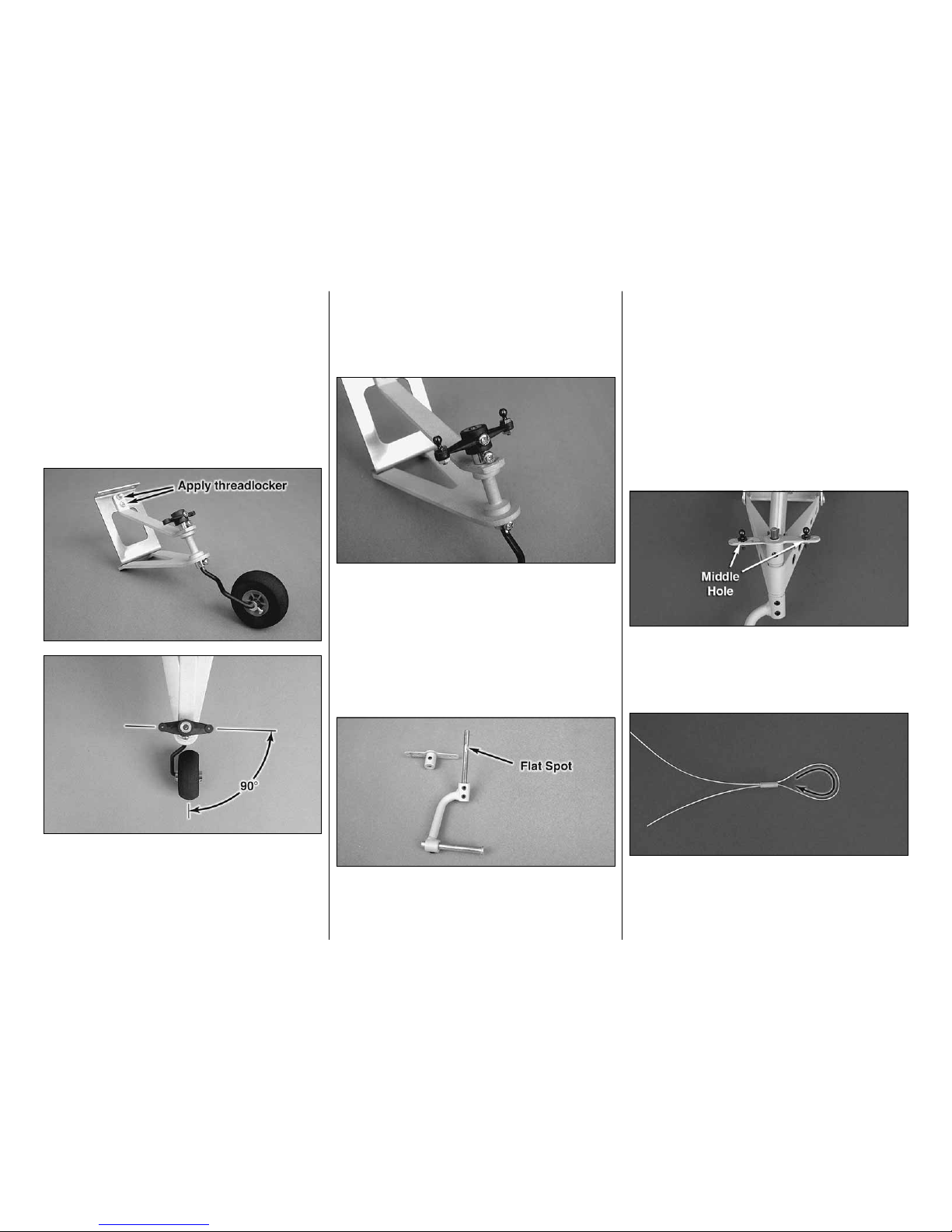
MOUNTTHE RETRACTABLETAIL GEAR
❏1. Remove the steering arm from the Robart
#160LWC retractable tail gear assembly (not
included). File a flat spot near the top of the shaft
for the set screw in the steering arm to lock onto.
Mount the steering arm to the shaft with a drop of
threadlocker and the set screw.
❏2. File another flat spot near the bottom of the
shaft for one of the set screws in the strut. Tighten
both set screws with a drop of threadlocker on each.
Be certain the steering arm and the axle in the strut
remain parallel with each other. Make adjustments to
the flat spots if necessary.
❏3. Enlarge the hole through the 1-3/4" [44mm] tail
wheel with a #9[5mm] drill.Cut the axle included with
the Robart retractable tail gear to the correct length,
then file a flat spot on it and mount it to the strut.
❏4. Enlarge the middle hole in both sides of the
steering arm with a 3/32" [2.4mm] drill. Insert a 2-56
ball link ball in the hole.Secure each ball with a 2-56
nut and a drop of threadlocker.
❏5. Use wire cutters to cut the supplied braided
cable into two equal lengths. Slide a small copper
tube (called a swage) over one end of the cables,
then guide the end of the cable back through.

17
❏6. Wrap the cable back around the swage and
back through the swage.
❏7. Use pliers to pull the cable from the first loop to
reduce the size of the second loop.
❏8.Now pull on the long end of the cable to reduce
the size of the first loop. Slip the loop over one of the
ball link balls on the steering arm. Tighten the loop
until it is small enough to remain secure on the ball,
yet may still be pried off. Squeeze the swage with
pliers. Connect the other cable to the other ball link
ball the same way.
❏9. Retractable tail gear only: Connect 40"
[1016mm] of purple air line to the forward air fitting and
40" [1016mm] of red air line to the aft fitting on the air
cylinder. There is not enough air line leftover from the
main gear, so additional line will have to be purchased
separately (Robart #169Pressure Tubing).
❏10. Place the tail gear in the fuselage while
simultaneously guiding the pull/pull cable through the
whiteplasticguidetubes.Ifinstallingtheretractabletail
gear, also guide the air lines through the fuselage.
❏11.Removethecoveringfromoverthetwotailgear
mounting holes in the bottom of the fuselage.Drill four
3/32" [2.4mm] holes through the rails for mounting the
tail gear. If your drill bit is not long enough to reach the
rail nearest the top of the fuselage, use medium CA
to temporarily glue a 3/32" [2.4mm] drill bit in a 1/8"
[3.2mm] brass tube.After drilling the holes, the drill bit
can be removed from the tube by heating the tube.
❏12.Mount the tail gear in the fuselage with four #6
x 1/2" [12.7mm] sheet metal screws.
After the British policy of giving names to aircraft
had caught on in the U.S., the XP-47B was dubbed
“Thunderbolt” by C. Hart Miller, Republic’s Director
of Military Contracts. Republic officially approved
the name.
18
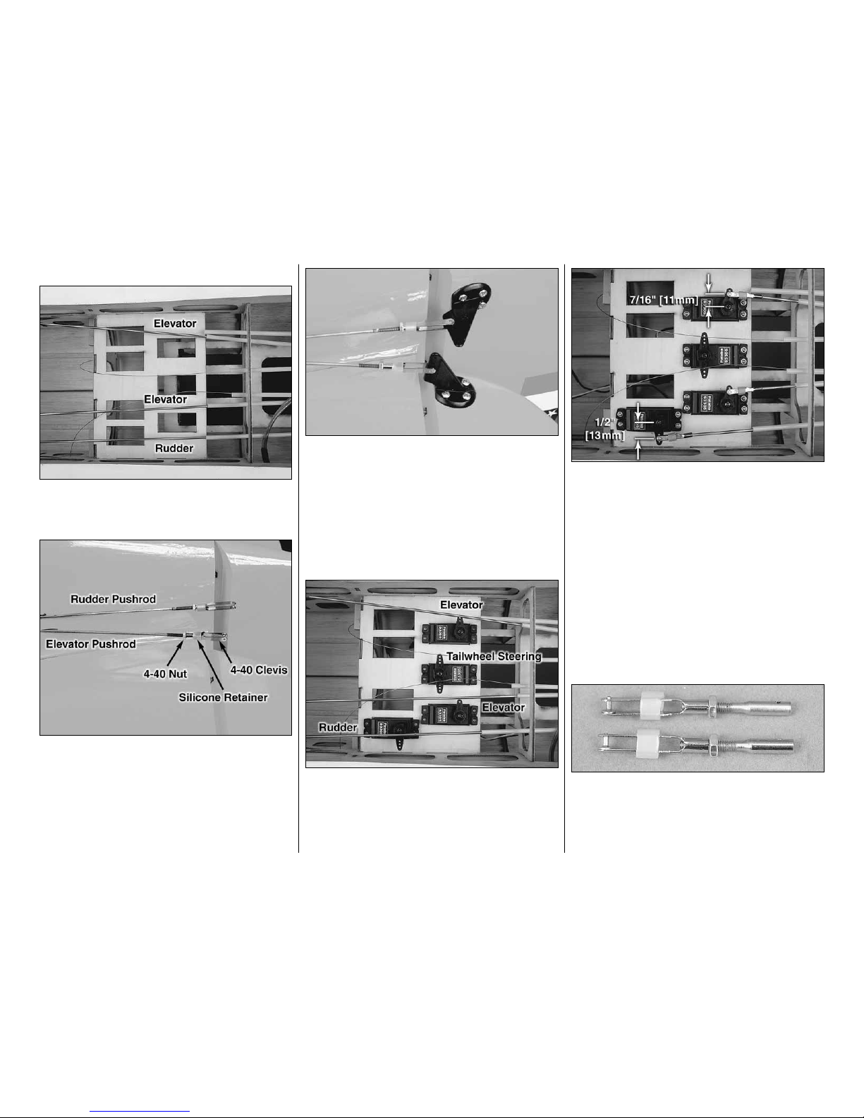
INSTALLTHE ELEVATOR & RUDDER SERVOS
❏1. Insert the three 4-40 x 48" [1220mm] metal
pushrods in the three outer pushrod tubes shown in
the photo.
❏2.Threada4-40nut,threaded clevisandasilicone
clevis retainer, 12 turns, onto both elevator pushrods
and the rudder pushrod.
❏3. Mount the control horns to the elevators and
the rudder. Follow the same procedure used for the
ailerons, by drilling 3/32" [2.4mm] holes and using
#4 x 1/2" [12.7mm] sheet metal screws. Attach the
elevator clevis in the third hole from base of the
control horn. Install the rudder clevis in the second
hole from the base of the control horn. Don’t forget
to harden the holes with thin CA after first installing,
then removing the screws.
❏4. Place two elevator, one rudder and one tail
wheel steering servo in the servo tray as shown.
Make three one-arm servo arms and one two-arm
servo arm from the servo arms that came with your
servos.Position the servo arms as shown.
❏5. Install solder clevises on the elevator servo
arms in the hole 7/16" [11.1mm] from the center of
the servo arm. Install a solder clevis on the rudder
servo arm in the hole 1/2" [12.7mm] from the center
of the servo arm. Following the same procedure that
was done for the aileron and flap pushrods, mark
the elevator and rudder pushrods where they are to
be cut for the solder clevises. One at a time, remove
the threaded metal clevis from the control horn end,
remove the pushrod from the fuselage, cut it to the
correct length and solder a metal solder clevis on the
end.Reinstall the pushrod from the front and connect
the solder clevis to the servo arms. Reinstall the
threaded metal clevis and 4-40 nut. Don’t forget to
use a silicone clevis retainer on all the clevises.
❏6. Thread a 4-40 nut and a 4-40 metal clevis, 12
turns, on to each of the 4-40 rigging couplers. Slide
a silicone clevis retainer over each clevis. Install the
cleviseson thetailwheel steering servoarm in theholes
7/16" [11.1mm] from the center of the servo arm.

19
❏7. Center the servo arm and the tailwheel gear.
Install a swage on each cable, securing it following
the same procedure used on the tail gear. Use a
pliers to crimp the swage tightly on the cable.
❏8. Mount the receiver on/off switch and charge
receptacle in a strategic location where it won’t
interfere with anything inside the fuselage and
where it will not get coated with engine exhaust
outside the fuselage.
❏9. Overlap by 1" [25.4mm] a 6" [152mm] long
piece of hook and a 6" [152mm] long piece of loop
material. Route the hook and loop material through
the two slots in the left forward fuselage side. Wrap
your receiver battery in R/C foam rubber and secure
it to the side of the fuselage with the hook and loop
material. Connect the receiver battery to the receiver
switch. Use the included heat shrink material to
secure the connectors. Make sure the receiver
battery is secure.
❏10. Mount the receiver on the other side of the
fuselage using hook and loop material. Connect the
receiver switch and the servos to the receiver. Route
the receiver antenna through the remaining pushrod
tube.Attach a strain relief on the antenna.
Early production Thunderbolts were not without
teething pains typical of any new aircraft. Takeoff
runs were long (nearly a half-mile to clear a fifty
foot obstacle) and there were several electrical and
hydraulic glitches, not to mention the unfamiliarity
of a totally new design.One fighter group damaged
or wrecked half of the P-47s received.
INSTALLTHE ENGINE
The following engine mounting instructions shows
the installation of the Fuji-Imvac BT-43EI-2 gas
engine.The installation of other brands of engines
will be similar and the following instructions can be
used as a guide.
❏1. The Giant P-47 ARF firewall has two sets of
engine mounting bolt patterns embossed on it. The
“X”is for the Fuji-Imvac BT-43EI-2 gas engine and the
“+” is for the DA-50 gas engine. If you are installing
an engine with a different mounting bolt pattern the
firewall also has crosshairs embossed on it to help
locate the correct mounting location.
❏2. Drill a 1/4" [6.4mm] hole through the firewall at
each location marked with an“X”.Install the M5 blind
nuts in the holes from the back of the firewall. Mount
20
the engine to the firewall using four M5 x 30mm long
andfourM5flatwashers.Applyadropofthreadlocker
to each bolt before installing. For reference, the
distance from the front of the firewall to the front of
the drive washer is 6-3/4" [171.4mm].With the Fuji-
Imvac BT-43EI-2 one of the 1/8" [3.2mm] plywood
engine spacers was required between the engine
and the firewall.
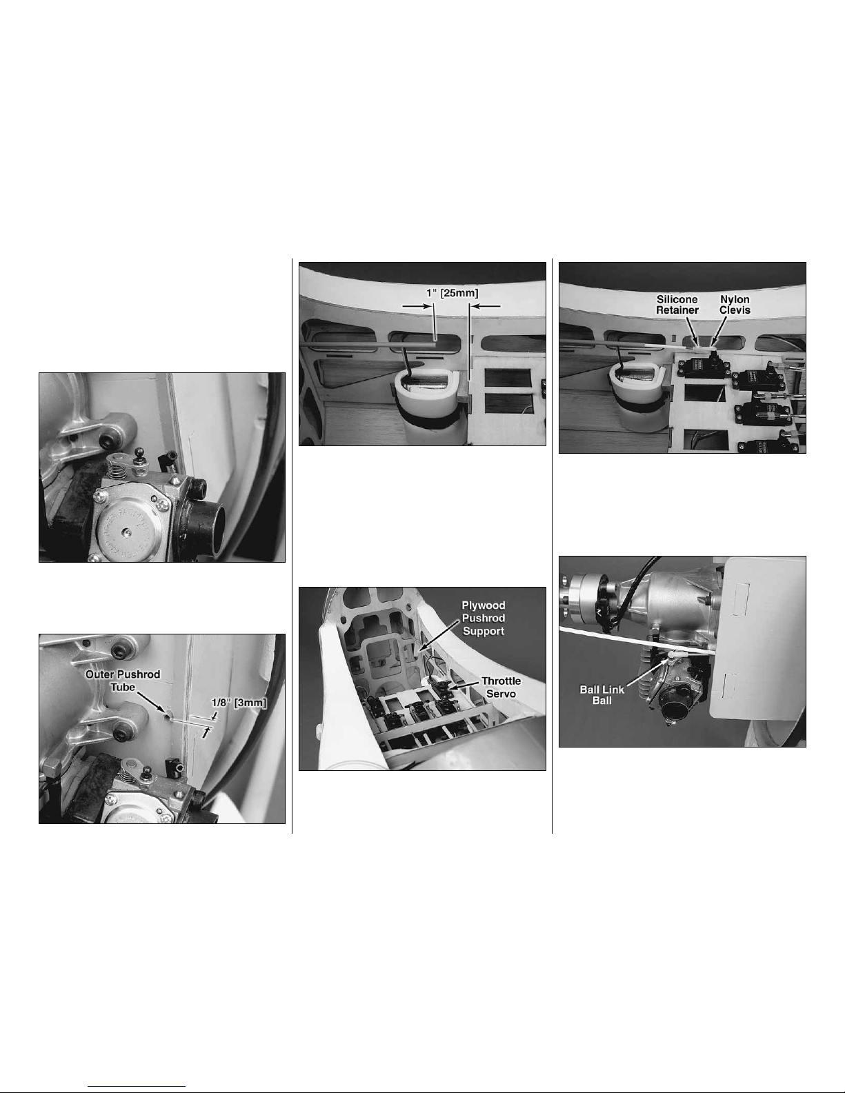
❏3. Install a 2-56 ball link ball on the throttle arm of
the carburetor. Secure the ball link ball with a 2-56
lock nut.
❏4. Drill a 3/16" [4.8mm] hole inline with the ball
link ball.Use medium sandpaper to roughen the gray
outer pushrod tube. Clean the tube with denatured
alcohol and insert the tube into the previously drilled
hole in the firewall. Route the tube through the front
formersofthefuselageuntilitprotrudesapproximately
1/8" [3mm] from the firewall. Use thin CA to glue the
tube to the firewall. Trim the tube approximately 1"
[25.4mm] in front of the servo tray.
❏5. Mount the throttle servo in the servo tray and
slide a plywood pushrod support onto the outer
pushrod tube.
❏6. Thread a 2-56 x 1" [25.4mm] threaded rod
approximately 3/8" [9.5mm] into the end of the white
inner pushrod tube. Thread a nylon clevis 14 turns
onto the end of the threaded rod. Slide a silicone
clevis retainer over the clevis. Attach the clevis to the
throttle servo arm.
❏7. Thread the nylon ball link socket 14 turns
onto the second 2-56 x 1" [25.4mm] threaded rod.
Attach the ball link socket to the ball link ball on the
throttle arm.
Table of contents
Other Top Flight Models Toy manuals

Popular Toy manuals by other brands

Fisher-Price
Fisher-Price Think & Learn FXW98 manual

Henseleit Helicopters
Henseleit Helicopters Three-Dee-Fun TDR-II user manual

MD Helicopters
MD Helicopters MILVIZ MD530F Rotorcraft flight manual

Kyosho
Kyosho RC SURFER instruction manual

Firelands
Firelands Eddie Rickenbacker's SPAD S.XIII Ultra-Micro... quick start guide

Eduard
Eduard B-26 Marauder interior Assembly instructions


