Henseleit Helicopters Three-Dee-Fun TDR-II User manual

Three-Dee-Fun
M A N U A L
Version 30.09.2017
Jan Henseleit
C A U T I O N! I M P O R T A N T!
Please read this manual before opening any bags!

Index
Safety Precautions page 3
TDF -Description / Technical data and RC component recommendation page 4 - 5
Introduction: Important! General information to be read before building page 6
Chapter 1 Main Rotor (Assembly Group 1) page 7 - 14
Chapter 2 Main shaft unit (Assembly Group 4) page 15 - 18
Chapter 3 Servo prepatation (Assembly Group 6) page 19 - 21
Chapter 4 Chassis (Assembly Group 2)
Servo mount –right chassis plate page 22
Servo mount –left chassis plate page 23
Bearing plate preparation page 24
Casssis mount page 25
Tail Boom mounting flange page 26
Chapter 5 Swash plate linkage
Aileron servo tooth rack (Assembly Group 6) page 27 –28
Elevator toothed rack (Assembly Group 6) page 29
Chapter 6 Lower chassis
Lower chassis (Assembly Group 2) page 30
Canopy mount back (Assembly Group 3) page 31
Skids (Assembly Group 3) page 32
Chapter 7 Installation of rotor shaft unit
Mount the main shaft unit into the chassis (Assembly Group 4) page 33 –34
Swash plate linkage (Assembly Group 6) page 35
Swash plate anti twist guide (Assembly Group 4) page 36
Plate for FBL system (Assembly Group 2) page 36
Chapter 8 Motor pinion unit + motor
Motor pinion unit page 37
Toothed tail belt disk + belt tensioner (Assembly Group 8) page 38
Motor mount (Assembly Group 7) page 39
ESC plate mount (Assembly Group 2) page 40
Installation of the motor unit to the chassis page 41
Quick exchange battery tray page 41
Chapter 9 Tail gear
Prepatation of tail gear housing right (Assembly Group 9) page 42
Mounting the deflection puller between the carbon housing (Assembly Group 9) page 42
Assembly of the belt disc (Assembly Group 9) page 43
Mount of the vertical fin plates to the tail boom (Assembly Group 9) page 44
Connect the tips of the vertical fin (Assembly Group 9) page 45
Tail pitch slider (Assembly Group 9) page 46
Belt crank (Assembly Group 9) page 46
Tail center hub with tail blade holders (Assembly Group 9) page 47 –48
Chapter 10 Tail boom
Mount of the tail boon to the mechanics (Assembly Group 8) page 49
Finish belt tensioner mount (Assembly Group 8) page 50
Rubber band mount (Assembly Group 8) page 51
Adjusting of the belt tension and clamping oft he tail boom page 52
Boom support (Assembly Group 8) page 53
Tail rotor ush rod (Assembly Group 8) page 54 - 55
Chapter 11 Installation of the remaining RC components
Mount of the ESC page 56
FBL system and receiver page 57
Flight batteries page 58
Chapter 12 Applying the decor on the canopy page 59 - 60
Chapter 13 Settings
Pitch page 61 - 62
Tail / ESC / Rotor blades page 63
Adjustable feathering spindle damping page 64
Chapter 14 First flight page 65 - 66
Dimentions page 67

Safety Precautions:
A remote controlled model helicopter is not a toy. Keep strictly out of reach for children.
A model helicopter will only perform reliably if assembled properly and regularly maintained
after each flight.
Keep sufficient safety distance from the model. Always assume technical failure could happen at any
given moment, which may cause the model to become out of control.
Only apply original spare parts in case of repair. Such may be acquired directly through me.
Sloppy assembly or repair work, as well as lack of experience in mastering a remote control,
may cause the model to become out of control and become a lethal hazard. The enormous rotating
energy of the main blades impose a permanent threat to anyone in the vicinity of the model.
Careless handling may cause any given sort of lethal injuries or property damage. Therefore,
refrain from overflying pedestrians and vehicles by all means.
Safety is the highest commandment within the scope of your sole responsibility.
The particular hazards involved are explicitly mentioned here, due to the fact that neither the
manufacturer nor the seller of these kit products has any influence on their use and operation.
Henseleit Helicopter corporation is not in the position to monitor an orderly use or operation
of the kit products. Therefore, Henseleit Helicopter corporation disclaims any sort of liability for
damages, injuries or consequential damages and injuries caused by the use of their product portfolio.
Diagrams, instructions, specifications and any other parts of my documentation are subject to
change at any given time. I disclaim any liability for printing errors. My documentations are
subjected to copy right regulations. Republishing any sort of text, diagrams or figures, require
my permission signed in hand written ink.
Jan Henseleit.

Th r e e - De e Fun
After delivered the TDR-II, pilots came often to me, asking for another helicopter close to the TDR, but technically up to
date. The TDR impresses by simpleness and was one of the most powerful and variable helicopters for years. It was
important for me, to have a machine in range , which can be flown with less powerful and cheaper drive components, but
with lots of fun.
Not only the weight is a big difference also the cost of a monster ESC and motor and huge flight packs are exceeding the
cost of the TDR-II may times over. For the new machine the components should be possible to use much cheeper and
lighter components.
This results in a light but stiff mechanic. Even the original TDR build in 2009 full filled this demands. But it was the time of
using stronger and stronger drives and the weight went up and up. This result in 700 Helicopters which have a weight
clear over 5kg. The playful flying was lost over the time. So I decide , that after developed TDR-II / TDS for extreme
powerful flying, its time to go - back to the roots - and develop a new helicopter for everyone.
My goal was a helicopter for fun flying, possible to use with simple components, but able to fly all figures the pilot want to.
It should als be possible to build powerful motor equipment for more extreme flying. It should not be a face lifted TDR
only but a totally new designed machine, with a lot of technical solution in, which I developed over the years and complete
new solutions as well. Weight should be lighter than the old TDR - which makes it necessary to construct with cleverness,
not to loose stableness or quality. With this new helicopter I followed my principles to implement trends, different from
usual constructions and follow new paths. The result is the TDFun.
TDF is the new 700 size helicopter for all pilots, which like a light weight agil 3D helicopter, build up clear and simple - but
having all necessary features which are recommend in a high-end helicopter. A fun machine which impresses by its flying
simplicity - even without monster motor systems.
During development the weight was always in focus - but also the technical refinement of a Henseleit helicopter was
newer lost. So the 700 size TDF presents itself with canopy by an empty weight of approx. 1800g. Finished in the lightest
version - with Midi size servos, JIVE ESC, PYRO 650 motor, as well as 6 or 7S flight pack (about 800g) - his total weight
is about 3650g - which is lower than most 600 size helicopters. Equipped with the most powerful components - standard
HV servos, KOSMIK ESC and PYRO 750motor, as well as 12S flight pack - the total weight is approx. 4700g, safely
under the 5kg border.
His gear in one step and the construction with the one way drive and tail gear drive inline with the motor shaft result in a
extrem easy and clear construction of the drivetrain. Different motors and flight packs allows to fly the TDF smooth but
also as a hot 3D machine. The gear ration is not changing.
My design of the LDS (Linear-Drive-System) is also realized in the TDF. Due to more space than in the TDR-II, it could be
kept very simple. This system has so many advantages that I do not want to miss it any more. TDF allows to use the
linear drive system with normal servos. Also the smaller, half price midi size servos are able to handle the necessary
force. There force of 8kg is plenty enough for this helicopter - precise controlling makes precise flying - thats 3D-Fun.
Due to the helical gearing of the one step main gear and the toothbelt drive tail gear the TDF is very quiet und clear in
construction. So easy to maintain.

Some parts of the TDF loyal Henseleit customers will know from the TDR and the TDR-II. So the canopy is the same as it
is for TDR, as this design is still nice and aero dynamic - with good visibility - nothing to improve. A new decal design
changes the view, but also the old design can be used if wished. TDR-II design has to be modified a bit, but can than also
be used. TDR customers can also use there existing canopies - it fits without changes.
The approved main rotor of TDR II has been modified for 12mm main rotor shaft and 8 mm feathering spindle, to save
weight. The adjustable damping was implemented - so adjustments can be done on the field in seconds.
Technical Data:
Name
TDF (Tree Dee Fun)
Manufacturing and sales
Henseleit Helicopters
Main rotor diameter
up to 1600 mm
Rotor blades
680 - 720 mm
Recommended rotor blades
710 mm / 175 - 210 g
Tail rotor blades
up to 110 mm carbon blades
Empty weight of the mechanic
approx 1800 g
Total weight - depending on used components
3.6 - 4.8 kg
Total length - tip of canopy to end of tail
1390 mm
Total height
390 mm
Maximum width of skits
190 mm
Maximum width of canopy
140 mm
Recommended motor
PYRO 650 –78 (6S setup)
PYRO 650 –65 (7S / 8S setup)
PYRO 700 –52 (for 10S)
PYRO 700 –45 (for 12S)
Maximum motor PYRO 750 –45 Competition (for 12S)
Recommended ESC
JIVE PRO 120+ HV
KOSMIK 160+HV depending on motor and flight syle (recommended only for PYRO 750
motors)
Gear ratio main rotor to tail rotor
1 : 5,56 (tail rotor is running during auto rotation)
Gear ratio motor to main rotor
9,27 : 1
Maximum flight pack size (L x W x H)
340 mm x 60 mm x 62 mm
When using 6S or 7S, the flight pack should be a weight of minimum 800 g.
Recomended servos and some general things
In gereral al standard servos can be used, but the TDF can also be flown with mid size servos
due to his weight and Linear Drive System, as 80 Ncm torque is more than enough.
Normally these servos are only half in weight of standard ones - so a total saving of about 160
g is possible.
Important is, tha there is no play in the servo and that the are precise in finding and holding
their position.
The enormous torque of up to 300 Ncm, the manufacturers are beating each other, I believe in
substantial exaggerating. Servos with more than 150 Ncm using in this helicopters are not
useful.
Even with 3 midi size servos the swash plate is pushed with nearly 25 kg (2 ½ baskets of
water).
Considered that the rotor blade with cyclical input and 1800 RPM on the main rotor change
from one side to the other about 30 times a second - you can imagine that the forces cannot
be as high, as the stud bolts would not stay in the plastic ball link if the force would be as high.

General information for the assembly (very important!)
Before you start, you should try to get an overview of the assembly by scrolling through the manual. It is recommended to
assemble the helicopter next to your computer. You can also print the manual.
Please start at the beginning of the manual and keep with the sequence of the assembly instructions. It makes no sense
to start in the middle of the manual. You can become easily stuck and lose track. Before starting a new assembly group,
first read the whole chapter description and then start mounting. It is not sufficient to view only the images because
the text contains important instructions that have to be considered in any case.
At the beginning of each assembly group you will find a part list with pictures, order number and name as well as the
number of pieces you need. Normal screws and connecting parts have different (grey) part numbers. These numbers are
also found under connection parts in our web shop. The part numbers of these parts are not shown in the pictures - only
the dimensions - e.g. M3x10. The picture shows, which type of screw has to be used. Caution! The length of screws is the
length of the shaft until the screw head. Only with countersunk head screws the length is the total length including the
head.
The assembly groups are packaged in separate plastic bags. Each plastic bag is labeled with the name of the assembly
group. Bulky or long parts are packaged separately. Complex assembly groups with a great number of small parts are
separated into several smaller bags.
Please open only the needed bag when required, as it is easily possible to loose the overview. You can identify the
needed bag by looking on the part list of the actual chapter. By means of the part number it's easy to identify the
corresponding assembly group for later spare part orders. The first number after zero is figure the assembly group.
All parts of the tail gear starts by 09 for instance. Sometimes parts have letters behind the 4 digit order number like
a/b/c/d/R/L/HS/RS. This letters show that the parts correspond and belong to one group or only have little differences.
The biggest mistake would be to open all bags at once. In the parts list of each chapter, you can find all parts of the
according assembly group. Sometimes there are screws inside, which have to be used later to fix different assembly
groups together. This is always described.
Attention! The drawings and 3D animations in the manual show a right-hand rotation. Left-hand rotation on this helicopter
is theoretically possible, but would need some modified parts. Right-rotation helicopters are mainly used worldwide. The
differences to left rotation are minimized due to the excellent flybarless systems.
Some parts of the helicopter are already pre-assembled. Nevertheless, this manual contains detailed instructions for
these parts. These instructions may be helpful in case you have to disassemble or to change parts. There is no need for
you to check the pre-assembled parts or to disassemble or tighten them! Also,the screws are secured with Loctite
already if necessary.
Attention! Screws, which need to be tightened with Loctite, are marked with a red “L”. Use the blue Loctite (medium
strength) or a similar product. Especially with the small grub screws, do not use too much Loctite. Otherwise, you may
have problems unscrewing the grub screws.
It is not necessary to tighten all screws of the electric helicopter with Loctite because they do not get loose depending on
the kind of stress. The lens-head screws can especially be hard to unscrew if using Loctite because of their small
hexagon.
In general, all grub screws and threaded link balls, as well as the 0911 screws of the tail centre hub, have to be
degreased and tightened with Loctite.
Attention! Parts that you need to pay extra attention to are marked with a red “!”. You will also find notes for these parts in
the text. Important screw tightening is marked with the recommended force. If a torque wrench is used you can be sure
about the correct tightening.
In case some items do not fit, do not use excessive force. Re-think why it may not fit together and see if a little reworking
might solve the problem. If you cannot solve the problem on your own, please contact me. Have a look at the carbon-fiber
reinforced parts. Use a strip of flexible sandpaper to chamfer the sharp edges if necessary.
Attention! When sanding Carbon fiber, use a fitted dust protection mask!
The helicopter consists of numerous screws and small parts. It may therefore occur that a part is missing or that the
screws are not shaped correctly or that they are rejects. Unfortunately, we are not able to check every single screw. In
these cases, please send us a short e-mail and we will immediately deliver the spare part. You will find a bag with some
special tools and special grease for the gears. A small extra bag (Reserve Parts) containing some established
replacement screws is also included there. Some replacement parts are available if a screw is missing or a part is
defective.
All in all, the assembly is not very demanding and does not require, besides some basic technical understanding, any
special skills. Please take your time and work diligently to avoid problems that later on might be more expensive and time-
consuming. Now I wish you a lot of fun assembling the helicopter!

Chapter –1 M a i n R o t o r (Assembly group 1)
A d j u s t a b l e f e a t h e r i n g s p i n d l e d a m p i n g
0140a Straining screw R-L-thread 1
0140b Thrust nut R- thread 1
0140c Thrust nut L- thread 1
Fasten both thrust nuts 0140b and 0140c to the collar
of the straining screw 0140a. Beforehand, apply some
of the lubricant “DRY FLUID HELI” onto the threads.
(has already been done before delivered). The
lubrication is indispensable (shake well before use).
Otherwise the threads will damage upon clamping
under pressure.
Attention! The nut 0140b with a single mark has a right-
hand thread. The nut with two marks has a left-hand
thread. There are no markings on the straining screw.
Find the matching threads by careful insertion.
Preferably start with nut 0140b (right-hand thread). This
will conclude the left-hand turns on the opposite side.
(note the direction arrows). The milled grooves of both
nuts need to be perfectly aligned by slightly unscrewing
one of the nuts. A slight difference between both gaps
to the collar is irrelevant.

8
F e a t h e r i n g s p i n d l e m o u n t
0102 O ring 14x3 - NBR80 8
0105 C-clip Seeger - JV-20 2
0109 O-ring inner bushing 2
0110 Feathering spindle 8x110 1
0120 Center hub 1
0140d Grub crew M3x4 2
General function description:
The image to your left shows the assembly structure of
the adjustable rotor head damper. The center part is
displayed in a sliced manner for better understanding.
Both of the thrust nuts are resting at their inner position
close to the collar. In this position, all O-rings are
relaxed.
The straining screw can be rotated with the 3mm pin (in
the tool bag) through the slot on the top of the center
hub 0120. The straining screw 0140a will push both
thrust nuts outwards. The O-rings are squeezed axial
and supported by the C-clips 0105 of the center hub.
This will increase the tension onto the O-ring inner
busher 0109 and the damping gets harder.
Both of the grub screws plunge into the slots of the
thrust nuts and thereby prevent the rotation of the thrust
nuts together with the straining screw.
Attention! Both of the grub screws may not insert to the
bottom of the slots (also refer to the following assembly
instruction).

9
First, apply some lubricant onto the O-rings 0102 and the O-ring inner bushing 0109. You may use a viscose bearing
grease or the enclosed “DRY FLUID GEAR” (Shake well before use). The inside of the center hub 0120 should also be
greased at the O-ring seat.
Only assemble one C-clip 0105 with C-clip pliers or a set of nose pliers tooled to fit into the clamping holes of the C-clip.
C-clips are punched out of sheet metal. They always have one sharp-edged side and one rounded-off side. Assemble the
sharp side facing outward so that the O-rings will have their seat onto the rounded side. Check if the C-clip has correctly
snapped into its groove. Now turn the open side of the C-clip into the rotational direction of the main rotor shaft / center
hub as displayed in the drawing. (If you look at the center hub from the top, it turns clockwise to the right)
Now, push four O-rings from the open side of the center part all the way to the averted opposite C-clip. Then insert the
pre-assembled straining screw unit into the center part. Both milled grooves of the two trust nuts should now be aligned
with the two M3 thread bores in the top side of the center hub. Then the next four O-rings are inserted and the second C-
clip is assembled as displayed in the drawing.
Both of the O-ring inner bushing 0109 are now inserted from left and right all the way through the O-rings until the stop.
Finally, the feathering spindle 0110 is inserted and aligned roughly to the middle.
The shaft usually has a tight fit in the jacks. Retain the averted opposite jack so that it will not be pushed out again while
inserting the feathering spindle.
Now align the two grooves for the grub screws 0140d with their threads in the top of the center hub. Perhaps you might
need a thin sharp tool to accomplish alignment. Carefully insert the grub screws 0140d into their M3 threads with a slight
touch of Loctite.
Attention! The grub screws should not be inserted aslant to avoid damage of their short thread. Now carefully screw the
grub screws to the bottom stop of the grooves. At the bottom, the grub screw will be nearly level with the top of the center
part.
Attention! Now the grub screws needs to be reversed exactly by one turn, equivalent to 0.5mm lash between the tip of the
grub screws and the bottom of the grooves! This is very important. The blade shaft including damper unit must have
enough clearance to avoid clamping nuts from hitting the grub screws during flight. Should this tend to happen, the grub
screws will be forced out and damage the threads of the center hub.
The assembly section bag contains a little bag inscribed with “rotation lock.” It contains a 4cm long silicon string with 3mm
in diameter. Later on, you will need 8mm of this silicon as rotation lock for clamping screw 0140a. Details will be referred
to in the chapter “adjustments.”

10
B l a d e h o l d e r
0107 Spacer washer 8x14x0,2 4
0113 Radial bearing 8x16x5 4
0114 Blade holder 2
0115 Axial bearing 8x16x5 2
0117 Spacer washer 5x10x1 2
0119 Hex socket screw M5x10 –12.9 2
First assemble the blade holder with all bearings. Attention! To avoid any mistake it is important to follow a specific
sequence. Both of the radial bearings 0113, which are pointing toward the center hub, are pressed into each blade
holder. If necessary, expand the blade holder with hot air. Make sure not to insert the bearing aslant. Now insert the axial
bearing 0115 through the fork of the blade holder. Apply enough lubricant onto all parts of the axial bearing in advance
(viscose grease into hollow side of ball cage). Pay attention to the correct sequence as displayed in the drawing. Each
ring has to be inserted laterally through the fork. At the beginning of the fork where the bore of the blade holder begins,
the rings are swiveled into rectangular position and pushed into the bore. Make sure the rings do not swivel by 180° and
carefully reassure that the grooves of the rings always point to the bearing balls. This procedure can be simplified with the
aid of a pin inserted from the other side, onto which you may align the rings. The first ring to be inserted has a 8.2mm
inner diameter. Then the ball cage follows with its hollow side pointing toward the center hub. Then you insert the ring
with an inner diameter of 8.0mm, followed by a spacer washer 0107 (8x14x0.2) and finally the radial bearing 0113.
Attention! To avoid aslant insertion, the final radial bearing should be assembled as follows.
After the axial bearing 0115 and the spacer washer 0107 are inserted, shove the bearing laterally between the fork and
swivel it into a right position.
If the radial bearing does not enter the blade grip without force, expand the blade holder with hot air. You can also use a
8mm pin to get the bearing aligned to the other bearings.

11
Finally slide both blade holders onto the feathering spindle. However, the spacer washers 0107 (8x14x0.2) need to be
inserted before, between the O-ring inner bushing 0109 and the pre-assembled blade holder.
In case the pre-assembled blade holders do not properly slide onto the feathering spindle, the predominant cause would
be a displacement of spacer washer 0107. In such case, use a pin to align the spacer washer with the rest of the bearings
and rings seated within the blade holder.
Now, secure the blade holder with washers 0117 and hex socket screw 0119. Tighten both screws 0119 with Allen keys.
The screws have their seat at the stop of the washers.
Attention! Only tighten the screws very slightly to begin with. The axial lash of both blade holders needs to be checked
first. Pull both blade holders apart forcefully. Measure the distance between both edges of the blade holders with the
inner beaks of a caliper. Subsequently, push both blade holders together forcefully and repeat the measurement with the
inner beaks of your caliper. The difference between both readings should not exceed 0.3mm. Should this be the case,
add washers (8x14x0.1 or rather 0.2) equally on both sides. The washers are found in an extra bag. Finally tighten both
screws 0119 forcefully with two Allen keys.
Attention! After tightening, the blade holders must still turn freely. If that is not the case, remove one set of washers. Upon
release of both screws, one screw will release first. Carefully remove the blade holder unit of the first release screw. To
obtain a tight grip onto the feathering spindle without damaging it, you would need a special shaft wrench. If you do not
have such a tool, I recommend to remove the other blade holder with the attached feathering spindle from the center hub,
in order to access the second washer. Avoid clamping nuts to slip away from the grub screws 0140d. Do so by carefully
pushing the feathering spindle out of the center hub with another 8mm shaft. It will serve as replacement for the
feathering spindle and keep all parts in position until the spindle, including blade holders, is reinstalled.
Attention! The screws 0119 are of high-grade steel and may only be replaced by original spare parts. The use of
conventional screw types bears the danger of tearing.
Please note! The basic adjustment of the rotor head damping will be outlined later on.
Do not try to pull the feathering spindle out of the bearings from the bent side after crashing. Always try to use the side
that remained fairly straight. Check on the first visible bearings 0113. The other bearings usually never take any damage.
Turn the inner ring of the bearings with a finger and check for smooth movement. These two bearings may be extracted
without removing all other parts of the blade grip unit. Push the old feathering spindle back into the damaged bearing until
the bottom of its inner ring. Then pull the bearing out by swiveling the shaft sideways to get some grip on it from the inside
(if needed expand blade holder with hot air). You may also use an 6mm spindle to push the bearing out by seating the
spindle onto the inner ring of the bearing through the fork side. Do not slide the blade holder units with violent force onto
the new feathering spindle. Sand down the new spindle if needed, with some fine-grade emery linen, while it is rotating in
a manual drill tool.
12
P i t c h a r m s
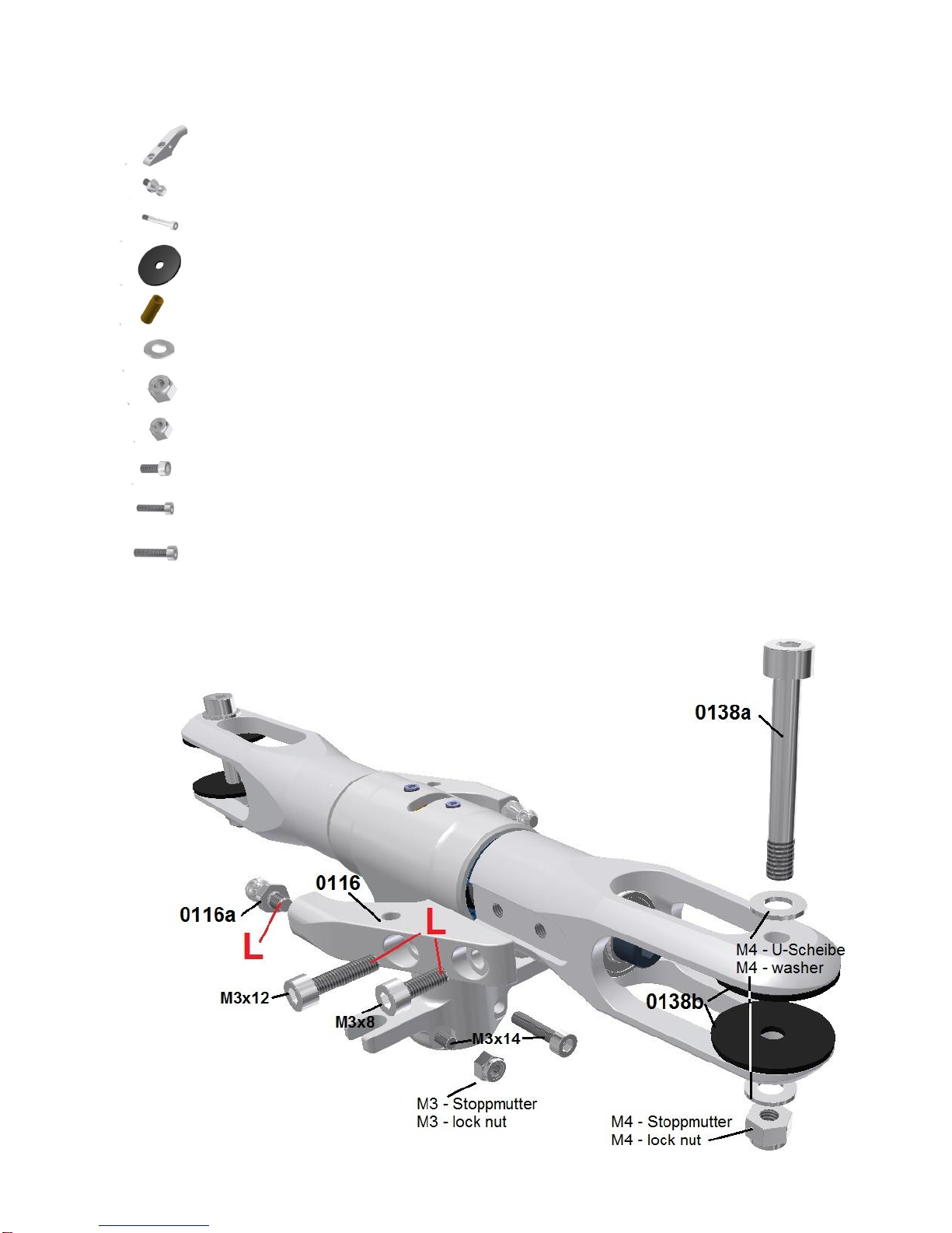
0116 Pitch arm 2
0116a Threaded ball stud M3x4 –6mm 2
0138a Blade bolt M4x30 –10.9 2
0138b Spacer for rotor blade 4x20x1 4
0138c Adapter sleeve 5mm to 4mm 2
W04 Washer M4 4
NS04 Nyloc nut –M4 2
NS03 Nyloc nut –M3 2
M0308 Hex socket screw –M3x8 2
M0312 Hex socket screw –M3x12 2
M0314 Hex socket screw –M3x14 2

13
Attention! Do not use an open-end wrench to tighten the ball stud. Use a socket wrench in order to not damage the
external hex.
The pitch arms 0116 has to be mounted in the grooves of the blade holder as shown in the picture. Look for the different
screw length M3x8 or rather M3x12 (use Loctite). Pull the arms into the fully outer position before tighten the screws.
Attention! By using the wrong screw length it is possible that the pitch arm is not fully fixed or the rotation of the blade
holder on the feathering spindle may be jammed.
Mount the blade bolts 0138a and the washer 0138b loose at the blade holder by the M4 nyloc nut not to loose them.
Don't forget the M4 washers as the M4 nyloc nut could not be fixed correctly without.
Also tighten the M3x14 screws loose with the M3 nyloc nut in the lower holes of the center hub 0120. They are for
clamping of the center hub at main shaft later.
Attention! At one side there is a hex socket to fit the nut, as on the other side is only a round hole for the screw head. If
the nut does not fit directly into the hex socket, move it step by step into a different position until it fits.
Main rotor head is ready and can be lay beside.
Attention! The bolts 0138 are of high-grade steel fabric and may only be replaced by original spare parts. Standard bolts
bear the great danger of tearing.
The two plastic spacer 0138b are needed to fill the gap when using 12 mm blades in the 14 mm blade holder. Do not use
the usual Aluminum washers - they will damage the blade holder or the blades.
When using blades with 14mm blade grips - the washers are not needed.
Reference: Sadly today most of the blade manufacturer do not deliver any reduction sleeves from the 5mm blade hole to
the 4 mm bolt used. Therefore one set of adapter sleeves 0138c is included in the kit.
This sleeves are for 12mm blade grip. For 14mm blades they can also be used if they are glued into middle position with
a small gap of 1mm on each side. 14mm adapter sleeves are available as well.
The adapter sleeves 0138c are also available as spare parts - for 12 and 14mm blades.
Do not drill out the blade holder hole to 5 mm, to use a 5mm bolt because a precise alignment is not guaranteed any
more.
The 4mm screw is absolute strong enough and takes more load than the usual M5 screw at the end of a 8mm feathering
spindle. So it makes no sense to use a M5 screw for the blades when not using M6 for the feathering spindle.
14
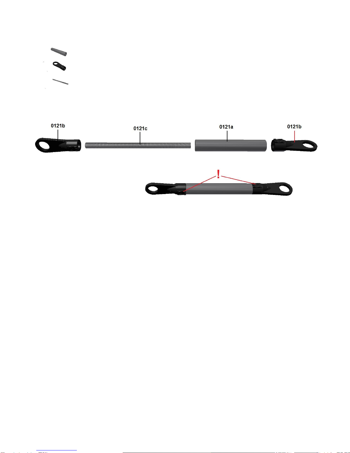
P u s h r o d f o r b l a d e c o n t r o l
0121a Spacer 30mm 2
0121b Ball link 15mm 4
0121c Stud bolt M2,5x 45 2
Mount the rod as shown in the picture above. Position the ball link in line to prevent damage.
Attention! Screw both ball links 0121b as far as it touches the spacer bush 0121a. Then rotate backward until the lettering
„2,5“ is in 90° position to each other as shown on the picture.
Do not try to screw the ball links further if they are touching to the bush, as the thread may be damaged and fixation is not
longer guaranteed.

15
Chapter –2 M a i n s h a f t u n i t (Assembly group 4)
S w a s h p l a t e
0400a Swash plate outer ring 1
0400b Radial bearing 45x55x6 1
0400c Swash plate inner ring 1
0400d Ball shell 1
0400e Ball 1
0400f Threaded ball stud M3x4 / 9mm 2
0400g Threaded ball stud M3x4 - 9mm (Special Elevator) 1
0400h Threaded ball stud M3x4 / 6mm 2
G0304S Grub screw M3x4 with tip 3
P2508 Phillips screw M2,5x8 4
C2506 Countersunk head screw M2,5x6 4
The base body of the swash plate will generally be delivered finally assembled. In case of a damage of the bearing the
swashplate can be disassembled to all single parts.
The proceeding of the assembly will be described in the following chapter. So in case of an exchange of the bearing you
understand the proceeding and what to take care about.

16
The bearing 0400b will be placed into the outer ring of the swashplate from above, without tilting. Slightly heating the ring
will ease the insertion significantly.
Secure the bearing with the three tapered grub screws M3x4 (see detail drawing below), placed in the lower radial hole of
the outer ring (use Loctite at the thread of the hole).
Attention! Tighten the grub screws carefully with feeling. Tighten them so that the tips just touch with light pressure the
upper radius of the ball bearing, securing it from slipping to the top.
Slide the inner ring of the swashplate 0400c from below into the ball bearing up to the shoulder.The ring should slide with
low force into the bearing. Grease the shoulder if necessary.
Now the inner ring will be secured by four M2,5x6 countersunk screws from sliding downwards. Also these screws have
to be tightened carefully until the cone sits on the radius of the ball bearing inner ring (use Loctite). Now there should be
now axial play between the swashplate inner ring and the ball bearing inner ring.
If the ball bearing itself has too much play between inner and outer ring (visible tilting) you can decrease this play by
stepwise tightening the three tapered grub screws. Tighten all three screws at the same level. This presses the outer
bearing ring some hundredths mm to the inside putting a little bit pressure on the balls.
Attention! Just tighten the grub screws so far that the bearing is still running smoothly.
With this method you can also correct an older worn bearing when it got too much play.
Grease the pivot bearing at the outside of the ball 0400e and the inside of the shell 0400d with Dry Fluid Gear (shake
before use). Then press the ball into the shell from the lower side. Insert the pivot bearing in the hole of the inner ring of
the swashplate and fix it with four Phillips screws M2,5x8.
Attention! Tighten the screws carefully and use Loctite.
In no case the ball is allowed to stick. A small axial play has no influence on the precision of the control.
The ball pins 0400f and 0400g at the outer ring and the ball pins 0400h at the inner ring have to be secured with Loctite.
Attention! Do not use an open-end wrench but a 5,5mm socket wrench to prevent the hexagon of the ball pins from
damage.
Attention! The ball pin 0400g has a slimmer shape and will be used for the connection of the elevator control rod later on.

17
M a i n s h a f t g e a r (Assembly group 4)
0416 Main shaft gear 1
0416a Carbon spoke 2
0416b Spacer 3x8x4 4
0418 Main gear flange 1
P2510 Phillips screw M2,5x10 8
N25 Nut M2,5 flat 8
M0312 Hex socket screw M3x12 4
WL03 Washer M3 large 4

18
To prevent the increase of the diameter of the main gear by heating even in case of hardest flying style, a special design
measure was taken. The delrin gear ring 0416 is manufactured with a 0,5mm smaller diameter as it should be. The inner
carbon spoke 0416a will not fit inside the gear in cold condition. For mounting the gear ring has to be heated in an oven
up to 60-70°C (140°-158°F). The gear ring will expand so the carbon rips can be inserted and positioned easily.
Put in two M2,5x10 Phillips screws at opposite sides through the holes of the carbon rip and the gear ring. The holes will
stay aligned also after cooling down.
Press the carbon rips down to the ground of the 2mm step of the gear ring. During cooling down the gear ring is shrinking
on the carbon rip and will be fixed with screws. All screws will be put from above to the holes and fixed with the M2,5 nuts
from below (use Loctite).
Now the nominal diameter of the gear is reached. Even under highest loading during flight the diameter will not increase.
It just could increase when the temperature of the gear will exceed 60°C (140°F) in operation.
Slide the complete gear on the gear flange 0418. In case of a too tight diameter you can grind the hole in the carbon rips
carefully until fitting without play.
Before fitting the gear with the M3x12 screws and the 3mm washers the four spacers 0416b (3x8x4) have to be placed
between the two carbon rips. You can place them easily through the holes of the rips and position them at the holes for
the screws.

19
Chapter –3 S e r v o p r e p a r a t i o n (Assembly group 6)
0630NS Elevator servo mount 2
0630RS Aileron servo mount 4
0630HS Tail servo mount 2
0634 Servo pad 8
0638 Threaded ball link M2x5 –3mm 1
0640 Servo gear - 28 teeth 3
N02 Nut M2 1
P2516 Phillips screw M2,5x16 16
NS25 Nyloc nut M2,5 16
L0306 Lense head screw M3x6 8
WL03 Washer M3 large 6
Generally the servos can also be installed when the helicopter is completely assembled. But I advise to prepare the
servos in this stadium to be able to install them in the next assembly step at the inner side of the chassis plates in
advance of the chassis mounting. This eases the work.
Attention! There are three different servo mountings: 0630NS (elevator servo), 0630RS (aileron servo) und 0630HS (tail
servo). Take care to use the right blocks for the respective servo and take care of the orientation of the M3 hole in the
blocks towards the right side according to the drawings.
The servos are positioned on the drawings (next page) in a way as looking from the right front side on the mechanics
when installed.
The blocks for the two aileron servos are identical and will be mounted with the thread orientated respectively to the right
and the left side.
The blocks for the elevator servo are a little bit longer. They can be distinguished from the other ones by the third hole
between the holes for mounting the servos.
The blocks for the tail servo are much longer and therefore easily to identify.
Note: All blocks are equipped with a larger hole so standard size servos (hole spacing=10mm) and midi servos (hole
spacing=7,5mm) can be fitted. The screws touch either the outside or the inside of the holes.
Unfortunately there are no standardized rubber fittings or spacers available by the servo suppliers. The fittings are from a
period were the servos were mounted on wood with wood screws and are inappropriate for today’s helicopters. Often the
mounting is too soft depending on the length of the spacers or the design of the rubber blocks. Therefore I recommend
either to shorten the spacers supplied with the servos to be able to compress the rubbers more or not to use them.
To get the necessary extensive pressure on the rubber blocks of the servos the servo pads 0634 will be used (see
drawing next page).
By equal torqueing of the M2,5x16 screws the rubber blocks can be pressed until the servos are fitted tight on their
blocks.

20
The following drawings show midi size servos with a housing width of 15mm. When using standard servos with a width of
20mm the blocks for the aileron servos are just 0,2mm wider on the side with the M3 thread.
E l e v a t o r s e r v o –p r e p a r a t i o n
The elevator servo will be screwed to the blocks 0630NS (three
holes) according to the drawing.
The servo pads are used to get the necessary extensive
pressure on the rubber blocks until the servos are fixed tightly
without play.
Torque the M2,5x16 screws and the 2,5 nuts stepwise and
equally. Take care that the blocks are correctly aligned.
This servo will be mounted at the next assembly step on the
inner side of the right chassis plate.
A i l e r o n s e r v o –p r e p a r a t i o n
Both aileron servos will be fixed similar to the elevator servo on
the blocks 0630RS.
Take care of the positioning of the M3 thread holes at the front
side which shall be facing to the left and the right outside.
These servos will be mounted later on in the inner side of the
left and right chassis plate.
T a i l s e r v o –p r e p a r a t i o n
In difference to the swash plate servos the tail servo will be
mounted with the upper side of the servo flanges to the servo
blocks 0630HS.
The servo lever will be mounted according to the drawing and
equipped with one ball pin 0638. The length of the lever should
be about 13mm.
The remaining M3x6 and M3 washers will be used to mount the
servos to the chassis plates (see chapter 4).
Table of contents


