manuals.online logo
Brands
  1. Home
  2. •
  3. Brands
  4. •
  5. Top Flite
  6. •
  7. Toy
  8. •
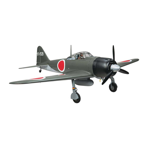
  9. Top Flite A6M2 ZERO Instruction Manual

Top Flite A6M2 ZERO Instruction Manual

BUILDING
THE
A6M2
ZERO
ProductSupport
(DoNotRemoveFromDepartment)
TOP FLITE MODELS, INC
CONGRATULATIONS'
You now own the most accurate
R/C
Stand-Off Scalekit ever
produced
We
at Top Flite hope thatyou willfindthis model the most
pleasant to build, inspiring to lookat and exciting to fly that you
have ever constructed
It
ishonest to point out,however, thatwhile this model is
no
more difficult- in factissimpler than most comparable kits to
make,
R/C
scale models generally are notfor the newcomer to
this hobby Previous modelingexperience and carefulattentionto
craftsmanshiparenecessary Even the "old hand"willdo wellto
study and follow the instructionsand guidance given in this book-
let.
It is-our aim to have you say "Thisisthe finestmodel I have ever
built".
TOPFLITE MODELS. INC
CONSTRUCTION OF THE A6M2 ZERO
BEFORE YOU START, READ THIS
The assembly sequence of yourTop Rite
ZERO
has been care-
fullydevelopedtohelpassure the correctalignment ofyourmodel
Utilize thecheck-offblocksas youbuild this will allow assembly
ofyourmodelinminimumtime
Before beginningan assembly step,read the instructionsto fami-
liarize yourselfwiththepartstobe used Findthepartsmention-
ed anddoublecheck themforproperidentificationandsize with
the plansDo notseparatepartsfromthedie cutsheetsuntilyou
need themThere aremachinedpartsinthekitwhicharenot
identifiedsuch asthe leadingedges, wingtips,etcThese parts
can be easilyidentifiedby checkingthepartsagainsttheplan.
We are sometimes asked which glues are best formodel construct-
ion The answerto thisdependsupontheparticularjobThis is
ournormalrecommendationFor allhardwoodtohardwoodor
hardwood-tobalsa joints,use white
wood
glue
"Titebond"
is
especially good, as itdriesfasterthanotherwhiteglues andis very
strongFor balsa-to-balsajoints,regularbalsa-wood cementsare
ample forthejob,althoughwhitegluecan be used here too.
Whichevertypeyouuse, rememberthatexcess glue is nosub-
stitutefora wellfittingjointUse a minimumof glue at all times,
and wipe offexcess glue thatsqueezes outofjointsbeforeit sets
hard,when set itisdifficultto remove, butif not removed it
could spoil the covering job.
IMPORTANTNOTETOBUILDER
Every model builtfroma kitis different,reflectingthelevel of
skill as well as thefavoredbuildingtechniques of themodeler
ultimatelythus,eachmodelis essentially theindividualcreation
of
thatbuilder.
Changes andvariationstakeplace in buildingsothatwhile Top
Flite supplies most essential buildingmaterials,theend product
isthe creationof thebuilder
Therefore, Top Flite assumes noresponsibilityfortheperform-
ance of themodel, nordoes Top Fliteassume any responsiblity
ofany naturewhatsoever fortheloss of, or propertydamage
resultingfromthe operation of this model when itis completed
1
USECOMMONSENSE
When you havecompleted this model, you will have invested
considerable time, money and skillProtect this investment by,
1.Re-checking allcritical buildingpoints(center of gravity,
hingeing of controlsurfaces,strengthof stress areas,etc ).
2.Correctly installing theradio gear
3.Test and re-test the radio, all moving surfaces,landing gear
(ifretracts),condition ofbatteries, etc.,
BEFORE EACH
FLIGHT!
4.OBSERVE ACADEMY OF MODEL AERONAUTICS SAFETY
CODE, particularlythose rulesgoverningRADIO CONTROLL-
ED FLIGHT DONOT FLY WITHOUT BEING FULLY
INSURED
WARNING!!
Aradio controlled model is nota "TOY" Care and caution
must be takenin properlybuildingthemodel as well as in
the installationand use of theradiocontrolleddevice Itis
importanttofollow alldirectionsas toconstructionof this
kit as well as installationanduse of theengine,propellers
andradiogear The advice andassistance of a well exper-
ienced builderandpilot ishighly recommended Don't
take chances Improperbuilding,operationor flyingof
model could resultin serious bodily injurytoothers,your-
self, or propertydamage
CONSTRUCTION
SEQUENCE
Followeach stepinorderandputcheck marks in
theblocks as you completeeach phase described.
The fuselageplans come intwo sheets The smaller
must becut along the dotted line and glued (or taped)
to the larger plan at the dotted lines Beforeyou do
anybuilding of this kit, we suggest you spend a few
hours reading and studyingthis book and the plans.
When you are ready,tape ortack the fuselageplans on a
flat
work
surface
Cover
the
working
area
of
the
plan
with
MonoKote backing orwaxedpaper
Trace pattern of Fin sheeting (3 pieces on each side)from
plans onto 1/16" x 2-7/8" balsa. Cut out and glue together
as shown above. Make two.
Do same thing withStabilizer.Make two.
PinFin sheeting over plan. Glue
R-7
inplace.Mark location
ofribs with softpencil.
Pin Stabilizersheetingoverplan. Glue
1/4"x 3/8" x 24"
inplace. Mark location of ribswith soft pencil.
Glue R-1.
R-2. R-3
& R-4 ribs inplace.Apply glue only up
to 1/4"from frontof rib.
Glue top sheeting inplace. Again apply glue only upto1/4"
fromfrontof rib.
Glue shaped leading edgeto ribs only. When dry, glue plank-
ingto leading edge on both sides. Besure that the planking
forms to the shape of the leading edge.
Construct rudder as shown inillustration above and the plans.
Make stabilizerand elevatorsusing same procedures asis
described
above._______
Glue
F-2A-2'sto F-2A-1 and F-3A-2 to F-3A-1.
Epoxy
F-1A(PLY),
F-2A ASSEMBLY and F-3A ASSEMBLY
all
together.
Glue former halves
F-5A thru F-16A
together, using plans
to measure correct width.
Pin notched strips(sometimes referred to as "crutch strips")
down over plans, locate frominner lineas the outer edge
of the stripwillbetrimmed offlater on.
Measure, cut and glue 1/4"SQUARE spacers inplace. Glue
1/4"x 1/2"SPACER and
F-23
inplaceat rear.
Glue formersF-5Athru F-14Ainplace.
Be sure formers
are perpendicular to notched strips.
Glue two
F-22's
inplace so they are 1/16"fromouter edge
ofnotched strip. Glue F-16A to F-22's and notched strip.
Glue F-17 in place.
Glue two pieces of
1/8"SHEET togetherandcuttofit for
cockpit floor.
Glue four
3/16" x 3/8" LONGERONS
into notches in
formers.
Cut notchinrear centerof stabilizer for clearance for elev.
control horn movement (see plan).
Epoxy elevator control hornto stabilizer atBRASS TUBING
ONLY!
Epoxy stabilizer to fuselage. Check alignment inalldirect-
ions.
Cut hole instab planking for fin leading edge and epoxy fin
place.Check alignment inall directions.
Drill holes for controlhorns inrudder and bothelevators.
andthen "Vee"notch. Make openings forplastichinges.
Attach rudder controlhorn to rudder with epoxy.Attach
rudder to finand epoxy brass tubing (only)torear of fin.
Attach elevators to stabilizer.
Glue
R-9
inplace. Fit
5/8" x 1-3/8" FILLET BLOCKS to
each side of rudder. Shape as required.
Fuselage canberemoved from plans.
Carefullyposition wing saddle assembly inposition onin-
verted fuselage halfand glue.
Epoxy former F-4B to front of wing saddle, to notched
strips and to motor mounts. Epoxy F-1BFirewallassembly
over motor mounts and to F-1Aassembly. Make sure fire-
wallsare flushand true inboth planes. Epoxy motor mount
support blocks inplace.
Make and glue all remaining formers
(F-10Bthru F-16B) i
n
position on notched strips.Glue 3/16" x 3/8"
LONGERONS
inplace[F-1Bassemblyto F-4B and F-10B to F-15B(or
F-16B)].
Bend TAIL WHEEL WIREas shown onplans.Over the
straight end, assemble a collar,the nylon tailwheelbracket,
F-20(PLY)(afterdrillinghole)and another collar.
Make two supports forF-20(PLY)fromscrap1/8" balsa and
glueinto position. Cut the 3/8" x 5/8" x 3-1/2" long balsa
block into two pieces to fitin between F-16B and F-17.
Glue the pieces inplaceand rouqh to shape only.
Laminate F-1B(PLY),
F-2B and F-3B
firewall as described
for F-1A assembly. Set aside to dry.
EpoxyF-19(PLY)doublers to insides of F-18 pieces.
Glue formers
F-5B. F-6B. F-7B, F-8B and P-9B
into theslots
inthe two F-18 pieces.
Epoxy 1/2"x 1-1/8"MOTOR MOUNTS tothe insides of
F-18's and F-5B and F-6B as shown. Motor mounts are to
extend out 4-3/8" fromends of F-18's.
Cut3/8"x 1-1/8"x 1-1/2" long maple block inhalf to make
two pieces 3/8" x 3/4" x 1-1/8". Epoxy these pieces into
thecut-outs inthe F-19(PLY)'s.
Trim andgluea
1/8"x 7/8" x 30"STRIP
to each side of
fuselage between the notched stripand firstlongeron.
Fit and glue a 1/8"
x2-7/8"(or 3") x 30"SHEET
between
next two longerons, on each side. Wood can beformedto
compund
shape
by
wetting
outside
only.
Hold
in
place
with
pins, tape and/or rubber bands whileglue is drying.
Finish top with 1/8"x 3-3/4"(or 4") x 24"
SHEET.
Leave
opening at cockpit area.(F-7Ato F-9A).
All seams should bein the approximatecenter of each long-
eron. Allsheetingis done on a "Fit and try"basis.
3
Install elevator and rudder servos. Make and rudder pushrods.
Check allcontrol surfaces forfreeand proper operation. Safety
all clevisesnow as they are hard to get at once the fuselageis
entirely sheeted.
Glue 1/8"x 7/8" x 42"
BALSA
toeach sideas shown.
Fit,formand glue 1/8"x 2-7/8"(or 3") x 42" SHEET nextto
7/8" wide pieces.
Pit, formand glue
1/8"x 3-3/4"(or4")x 24"SHEET
inlast
opening.
When shellsare dry, trim carefullyaround wing opening. Plank
(cross grain) openings from over formers F-4B thru F-10B with
1/16"balsa sheet.
Glue
1-1/8" x 2-1/2" x 2-3/4" TAILBLOCK
inposition.
Carve and sand to shape. Sand entirefuselage, cutting down
raised
edges
ofnotched
strip
until
flush
with
sheeting
For access to interiorof fuselage,cut out formers
F-5B, F-6B,
F-7B, F-8B and F-9B frombetween F-18pieces.
Tape
4
pieces
of
3/32"
x
2-7/8"
x
30"
Balsa
and
two
pieces
of
3/32" x 2-7/8" x 15"BALSA
together as shown above. Make
two sets.
Turn them over, open upslightly, and apply glueto joints. Lay
onflatsurface,withweights, until dry.
Cuta triangular piece, as shown shaded above, off of each
piece and SAVE.
Make two more sets, using the triangle, three 3/32" x 2-7/8" x
30"and two 3/32" x 2-7/8" x 15"foreach set.
Cover wing plan with MonoKote backing.Pinoneassembled
over outlineon plan.
GlueribsW—3thruW—11to spar, pinning thru feet of ribs,
checking to besure ribs are perpendicular.
Glue
W—22
to
front
of
each
rib
and
pin.
Glue
7/16" THICK x 28" LONG TAPERED
piece to back of
ribs and pin.
Glue upper spar inposition inrib notches.
When wing isdry,takeDIHEDRALGUIDE as shown above,
mark linesand cutoff spars, W—22andtrailing edge. Unpin
from plan.
Build opposite wing panel inexactlysame manner.
Glue
W-3B(PLY)
and
W-3C(PLY)
to
W-3 RIBS.
Make one
left hand and one right hand.
Glue W-5B(PLY)and W-5C(PLY)to W-5 RIBS. Make one
left hand and one right hand.
Cut four pieces of 1/4"x 1/2"
BALSA
stripsto 12-9/16"
long.Taper one end of each piece as shown.
Glue these strips to 1/4"x 1/2"x 30"SPARS, 15-1/8" from
oneend of each stripas shown. Leave excesslength onspar
to aid inpinning down. Make foursets.
4
Glue
W-2C
inplace on W-2B rib.Cut out one W-1B to same
length
as
W-2C
as
shown
above
(both
W—1A'S
if
flap
servo
is tobeused).
Epoxy
1/4"x 3/8" SERVORAILS
inplaceusing servo as guide
for spacing. Installservo(s).
Make
CONTROL WIRES
as shown above (ball link connectors
arerecommended at servoend).
Glue
W-8B
inplace onW-8 rib.Glue
W-9B
inplace.
Mount
BELLCRANKASSEMBLY(see
plans)to
W-12(PLY)
and epoxythisassemblyon W—8Band W—9B.
Plank top of wingpanel that is stillpinned down.
Remove wingfrombench and pin down oppositewingpanel.
Repeat plankingprocedure on thispanel. Unpin and remove
allrib feet.
Epoxy
L.G. KEYBLOCKS
to W-3 ribs. Epoxy
GROOVED
L.G.BLOCK inrib notches. Locate fromplans. Drill7/32"
dia. hole to lineupwithgroove in key block
Locate and cut openings forcontrolwiresand main L.G.
wires, inwing planking. Plank both bottom wing panels.
Glue WING TIP blocks together and saw to outline. Glue
wingtips to wings, and shape.
Shape leading edges per plan. Sand wing allover.
Hinge
ailerons
permanently
to
wing. If
flaps
are
to
be
oper-
ating, hinge them permanently, otherwisecement them in
place. Connectcontrolsto ailerons(andflaps).
Glue
W-21
to center of 3/4" faceof 3/8" x 3/4"
STRIP.
Mark location of each rib fromthe plans. Cut 3/32" x 3/8"
BALSA
to length foreach rib, and glue them inplace top
and bottom. When dry,taper ribs with sandpaper blockor
razor plane. Make two ailerons.
Bevel frontof leading edge as shown. Install three
NYLON
HINGES.
See plans forinstructions.
Glue W—28(PLY)'sinplace top and bottom. Location of
W-28(PLY)'sdetermine L.H. orR.H. aileron.Make one each.
Install
NYLON
HORNS
with #2-56
x
1/2"
R.H.M.S.
Leave last wing panel built pinned to work table. Joinwing
halvestogether using
W-16(PLY)JOINERS and
slow drying
epoxy.Block upopposite wing panel for correct dihedral.
Epoxy
W-17(PLY)'s
to W-16(PLY)'s.
Crack W-13(PLY)and W-14(PLY)incenter to conform to
angle of leadingedge. Epoxyinplace as shown.
Shape
17/32"
x
1-3/16"
x
7"
BALSA
BLOCK
to
conform
to
shape of trailingedge. Epoxy inplace. Epoxy W—18(PLY)to
thisblock.
Glue
two
W-1A's
and
two
W-1B's
together.
Epoxy
them
in
place inwingasshown.
Assemble
HARDWOOD BLOCK,
W-2D's,W-19's and W-3D's
as shown above. Filler wedges aremade fromscrapbalsa.
5
Again the decisionto use landing gear retractsmust bemade before
construction begins Construction provisionshave been built into
the model forretractsThere is room inthe center of the wing,
foreward of the main spars, fora servo (mechanical retracts)ora
servo and valve(pneumatic retracts)The airsupply tank (pneum
system) islocated inthe fuselage Be sure the tank(s)and airlines
DONOT INTERFEREwiththe pushrod operation The model
canbebalanced with the wheels upordown as the fore and aft CG
remains the same
Thisplane isdesigned to have operating flapsifdesired The flaps
willhave to behinged and control horn added, instead of fastened
solid as shown on plans Provisionshave been made inthewing
for the additionalservoThedecisionto have operating flapsmust
bemade before the wing construction isstarted
Drill 1 /4" diax 1 3/4" deep hole inleading edge incenter of
wing Install
1/4"DIA x 2" LONG DOWEL
withepoxy
Dowel should stickout at least1/4" Sand slightradiuson
end of dowel
Epoxy faceof
F—21
(PLY)and slip over dowel with epoxy
away fromwing Do not get epoxyon dowel Put the wing
with F—21(PLY)inplace on the fuselageand aligncarefully
Temporarilyfastenitdown Thiswillcorrectlylocate the
F-2KPLY)on the fuselage
When the epoxyhas set and while thewing is still fastened
down, drilltwo 1/8"DIA holes thruwingand thru fuselage
blocks See plans forlocationdimensions
Glue F-10C to wing only(notto fuselage)Glue
F—9C
on
wing See plan forlocation Maketwo crosspiecesfromscrap
1/8"stock Sheet overthisareawith1/8" softsheeting
Remove
wing
Tap
fuselage
holes
with
#8-32
self
tapping
screw
furnished
Drill
wingholes
out
to
11/64"
DIA
for
screw clearance Cut notches inplanking forscrew head
clearance
Drill holes infirewall at properlocations for throttle and
mixturecontrols and fuel line Installengine—60to 90re-
commended Attachfuel line Installthrottle andfuel mixture
control cables Check forfreemovement
Installthe radioequipment (receiver,battery, servos, etc ) as
perthe manufacturers instructions
Make cut outs in
FRONT COWL
forexhaust,glow plug,etc
Cement to rear cowl and sand lightly with400 gritpaper
prior to painting
Attach
W-26(PLY)L.GDOORS
to main landing gear wire
as shown on plans , Installmain wheelsand tailwheel
Cover the model (exceptcowl)withcolored
MonoKote,
or
orcover the model with
CHROME MONOKOTE,
paint as per
color desired and then scribepanel outlines
Paint cockpit withflatblack Install pilot (not furnished) Trim
andinstall vacuum formed gunports and canopy See plans for
adhesives to use Apply markings furnished
Check radio carefully,including range check permanufacturers
instructions Check Center of GravityDo not deviate from
position shown on plans If youarenot a proficientR/Cpilot,
getthe help of one
See
warning
on
page
1
Save
your
plane-
avoid grief
Temporarily center the REARCOWL onfuselage sothat the
mounting holesareat 45°to the verticaland horizontalcenter
lines
of
the
fuselage
Mark location
of
holes
with
softpencil
Removecowl and drill
1/8" DIA
holes thru at marks
Drill a 3/16" dia hole inthe center of each F 23(PLY)
piece
Press
a
#4—40
blind
nut
firmly
in
each
one
Fasten
the
rear
cowl inplace
with
four
#4-40
x
3/4"
RH M S Use the F 21 (PLY)withblind nut inside the
fuselaqe
With wing bolted inplace, form and fitwing fillets
W-23,
W-24 and W-27 Allfilletson each side ofthe wingmust
bedone at the same time forproper fittingW 23's are
fixedto the wingwhileW 24 and W 27 are fixedto the
fuselage Smooth jointswithDap
6
Fora 16-pagecatalogplusa free MONOKOTE™
sampleandpropchart, sendrequest
plus50centsto TopFlite
©TopFlite Models,Inc.1981150308'

Other Top Flite Toy manuals

Top Flite Giant F4U Corsair User manual

Top Flite

Top Flite Giant F4U Corsair User manual

Top Flite Elder Biplane RC-37 User manual

Top Flite

Top Flite Elder Biplane RC-37 User manual

Top Flite Giant F4U Corsair User manual

Top Flite

Top Flite Giant F4U Corsair User manual

Top Flite Sierra User manual

Top Flite

Top Flite Sierra User manual

Top Flite Gold Edition Nobler User manual

Top Flite

Top Flite Gold Edition Nobler User manual

Top Flite Contender User manual

Top Flite

Top Flite Contender User manual

Top Flite Cessna 182 ARF User manual

Top Flite

Top Flite Cessna 182 ARF User manual

Top Flite Stinson Reliant User manual

Top Flite

Top Flite Stinson Reliant User manual

Top Flite GIANT SCALE GOLD EDITION ZERO User manual

Top Flite

Top Flite GIANT SCALE GOLD EDITION ZERO User manual

Top Flite Giant Scale Gold Edition P-51D Mustang User manual

Top Flite

Top Flite Giant Scale Gold Edition P-51D Mustang User manual

Top Flite Giant Scale Gold Edition P-51D Mustang Installation and operating instructions

Top Flite

Top Flite Giant Scale Gold Edition P-51D Mustang Installation and operating instructions

Top Flite P-40 Warhawk User manual

Top Flite

Top Flite P-40 Warhawk User manual

Top Flite P-47D Thunderbolt User manual

Top Flite

Top Flite P-47D Thunderbolt User manual

Top Flite P-47 Razorback User manual

Top Flite

Top Flite P-47 Razorback User manual

Top Flite F6F Hellcat User manual

Top Flite

Top Flite F6F Hellcat User manual

Top Flite Giant Scale Gold Edition P-51D Mustang User manual

Top Flite

Top Flite Giant Scale Gold Edition P-51D Mustang User manual

Top Flite Giant Scale Gold Edition P-51D Mustang User manual

Top Flite

Top Flite Giant Scale Gold Edition P-51D Mustang User manual

Top Flite AT-6 Texan User manual

Top Flite

Top Flite AT-6 Texan User manual

Top Flite NOBLER ARF User manual

Top Flite

Top Flite NOBLER ARF User manual

Top Flite Giant F4U Corsair User manual

Top Flite

Top Flite Giant F4U Corsair User manual

Top Flite FW 190 User manual

Top Flite

Top Flite FW 190 User manual

Top Flite T-34B MENTOR User manual

Top Flite

Top Flite T-34B MENTOR User manual

Top Flite Mini Contender Ep User manual

Top Flite

Top Flite Mini Contender Ep User manual

Top Flite Elder RC-32 User manual

Top Flite

Top Flite Elder RC-32 User manual

Popular Toy manuals by other brands

LEGO Mindstorms EV3 Build instructions

LEGO

LEGO Mindstorms EV3 Build instructions

Lionel Union Pacific ALCo PA owner's manual

Lionel

Lionel Union Pacific ALCo PA owner's manual

Air Rage Microfighters instruction manual

Air Rage

Air Rage Microfighters instruction manual

GREAT PLANES Reactor instruction manual

GREAT PLANES

GREAT PLANES Reactor instruction manual

REVELL German Heavy Cruiser Prinz Eugen Assembly manual

REVELL

REVELL German Heavy Cruiser Prinz Eugen Assembly manual

Mega Bloks 7860 quick start guide

Mega Bloks

Mega Bloks 7860 quick start guide

Mega Bloks Call of Duty 06855 instructions

Mega Bloks

Mega Bloks Call of Duty 06855 instructions

Crooza MABU-01 Operation manual

Crooza

Crooza MABU-01 Operation manual

Multiplex FunCub NG 1-01333 manual

Multiplex

Multiplex FunCub NG 1-01333 manual

Lionel Boom Car owner's manual

Lionel

Lionel Boom Car owner's manual

Bengtson Company Albatros CIII 38 instructions

Bengtson Company

Bengtson Company Albatros CIII 38 instructions

Flex innovations FV-31 Cypher Addendum

Flex innovations

Flex innovations FV-31 Cypher Addendum

Flex innovations Super PNP F-100D Super Sabre instruction manual

Flex innovations

Flex innovations Super PNP F-100D Super Sabre instruction manual

Aquacat TURBO X operating instructions

Aquacat

Aquacat TURBO X operating instructions

marklin 37039 user manual

marklin

marklin 37039 user manual

REVELL Krupp Protze Kfz.70 & 3.7-cm-pak Assembly manual

REVELL

REVELL Krupp Protze Kfz.70 & 3.7-cm-pak Assembly manual

bruder Fliegl 02203 Instructions for use

bruder

bruder Fliegl 02203 Instructions for use

myToys 5528114 Assembly instructions

myToys

myToys 5528114 Assembly instructions

manuals.online logo
manuals.online logoBrands
  • About & Mission
  • Contact us
  • Privacy Policy
  • Terms and Conditions

Copyright 2025 Manuals.Online. All Rights Reserved.