TOP GUN WELDING TGWTIG195DCPULSE User manual

USER MANUAL
TOPGUN TIG 195 AMP DC PULSE


Contents
1. Safety warning...................................................................................................... 1
2. Description of TIG pulse welding machine...........................................................6
3. Technical data....................................................................................................... 7
4. Installation.............................................................................................................8
5. Operation instructions........................................................................................ 10
6. Daily maintenance and checking........................................................................ 14
7. Trouble shooting and fault finding..................................................................... 16
USER MANUAL
1
1. Safety warning
The safety notes listed in this manual is to ensure correct use of the machine and to keep you and other people from
being hurt.
The design and manufacture of welding machine considers safety. Please refer to the safety warning listed in the
manual to avoid accidents.
Different damage would be caused by wrong operation of the equipment as follows. Please read the user manual
carefully to reduce such damage.
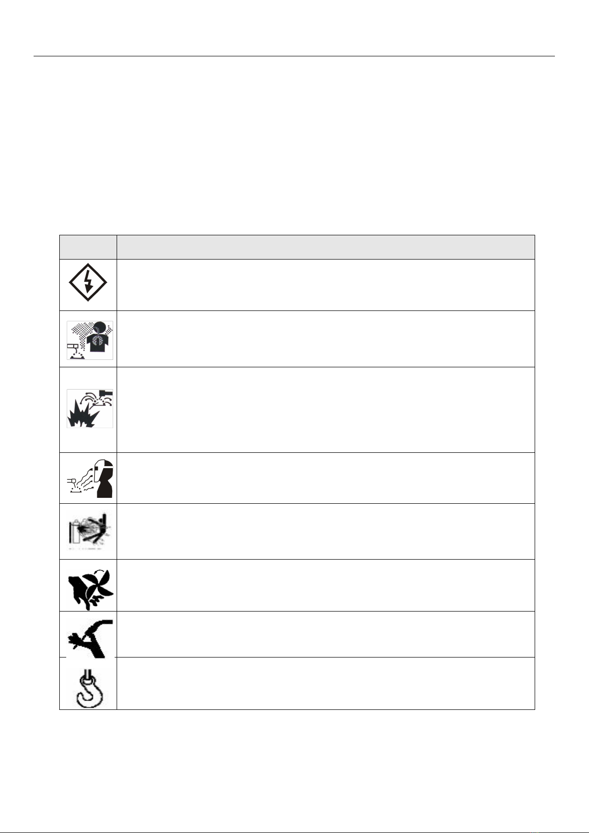
Sign
Description
Any contact of electric parts may cause fatal electric shock or burnt.
Gas and fumes are harmful to health.
Operation in narrow space may cause choke .
Spark and hot workpiece after welding may cause fire.
Bad connected cable may cause fire.
Incompletion connection of workpiece side circuit may cause fire.
Never weld on the case of tinder stuff, or it may cause explode.
Arc ray may cause eye inflammation or skin burnt.
Spark and residue will burn your eyes and skin.
Toppling over of the gas cylinder will cause body hurt.
Wrong use of the gas cylinder will lead to high-pressure gas eruption and cause human
hurt.
Never let fingers, hair, clothes or etc. near the moving parts such as the fan.
The wire shoot out of the torch may stab eyes, face and other naked parts.
Never stand in front of the swang equipment or under it, or it may fail and cause injury.

USER MANUAL
2
Please follow the rules below to avoid heavy accidents.
Never use the equipment to do other things but welding.
Follow related regulations for the construction of the input-driven power source, choice of place, usage of
high-pressure gas, storage, configuration, safe-keeping of workpiece after welding and disposal of waste, etc.
Non essentials do not enter the welding area.
People using heart pacemaker is not allowed to get close to the welding machine or area without doctor’s
permission. The magnetism created by energizing the welding machine can have a bad effect to the pacemaker.
Install, operation, check and maintain the equipment by profession personnel.
Understanding the contents of the user manual for safety.
Please follow the rules below to avoid electric shock。
Keep away from any electric parts.
Earth the machine and workpiece by professional personnel.
Cut off the power before installation or checking, and restart 5 minutes later. The capacitance is chargeable
device. Please ensure it has no voltage before start again even if the power source is cut off.
Do not use wire with inadequate section surface or damage insulation sleeve or even exposed conductor.
Do ensure well isolation of wire connection.
Never use the device when the enclosure is removed.
Never use broken or wet insulation gloves.
Use firenet when work at high position.
Check and maintain regularly, don’t use it until the broken parts are fixed well.
Turn off the power when not in used.
Follow the national or local related standard and regulations when using the AC welding machine at narrow or
high position.
Please follow the below notes to avoid fire and explode, etc.
No combustible in welding area.
Keep off combustible when welding.
Keep hot workpiece after welding away from flammable gas.
Do move away the combustible around when weld the dooryard, ground and wall,.
The wire connection of base metal should be as close to the welding place as possible.
Never weld those facilities with gas pipe or airtight slot.
Put fire extinguisher around the welding area to prevent fire.
The gas and fumes are harmful to health, please wear protective device according to
regulations.

USER MANUAL
3
Wear exhaust equipment and breathe preventive facilities to prevent gas poisoning or choke.
Use suggested part exhaust equipment and breathe preventive facilities to prevent hurt or poisoning by gas and
other powder, please.
To prevent oxygen-deficiency, air out the gas-filled room which is full of CO2and argon on the bottom, When
operating on trunks, boilers, cabins, etc.
Please accept the supervisor’s inspection when operating in narrow space. Air the room and wear breathe
preventive facilities.
Never operate in degrease, washing or spray space.
Using breathe preventive facilities when weld shielded steel for it will cause poisonous dust and gas.
The arc, spark, residue and noise are harmful to health, please wear protective appliance.
Eye protection against arc is recommended when welding or supervise welding.
Please wear preventive spectacles.
Welder’s gloves, welder’s goggles, long sleeve clothes, leather apron, and other standard protection equipments
must be worn for welding operation.
A screen to protect other people against the arc must be set in the welding place.
Please follow the notes below to avoid gas cylinder toppling over or broken.
Use the gas cylinder correctly.
Use the equipped or recommended gaseous regulator.
Read the manual of gaseous regulator carefully before using it, and pay attention to the safety notes.
Fix the gas cylinder with appropriate holder and other relative parts.
Never put the cylinder under high temperature or sunshine environment.
Keep your face away from the gas cylinder exit when opening it.
Put on the gas shield when it is not used.
Never put the torch on the gas cylinder. The electrode can not meet the gas cylinder.
Any touch of the switch part will cause injury, please note the following.
Never use the machine when the enclosure is off.
Install, operate, check and maintain the machine by professional person.
Keep your fingers, hair, clothes etc. away from the switch parts such as the fan.
The wire end may deal damage, please note the following.
Never look into the electric conduction hole when checking the wire feeding is normal or not, , or the shooting
wire may stab your eyes and face.
Keep your eyes, face or other naked parts away from the end of torch when feeding the wire manually or
pressing the switch.

USER MANUAL
4
For better work efficiency and power source maintenance, please note the following.
Precautions against toppling over.
Never use the welding equipment for pipe thawing.
Lift the power source from side when use the up-down forklift truck to avoid toppling over.
When using the crane for lift, tie the rope to the ears with an angle no more than φ15 to the vertical direction.
When lifting the welding machine which equipped with gas cylinder and wire feeder, download them from the
power source and ensure the horizontal of the machine. Do fix the gas cylinder with belt or chain when moving it
to avoid body hurt.
Ensure fastness and insulation when lifting the wire feeder through the swing ring for welding.
Electromagnetic interference needing attention.
It may need extra preventive measures when the equipment is used in particular location.
Before the installation, please estimate the potential electromagnetism problems of the environment as follows.
a) Upper and lower parts of the welding equipment and other nearby power cable, control cable, signal cable and
phone cable.
b) Wireless electric as well as TV radiation and reception equipment.
c) Computer and other control equipment.
d) Safety-recognition equipment etc. Such as supervise of industrial equipment.
e) Health of people around. Such as personnel using the heart pacemaker or audi earphone.
f) Equipment for adjustment and measurement.
g) Anti-disturb capability of other used equipment .Users should ensure these equipment and the environment
are compatible, which may need extra preventive measures.
h) Practical state of the welding and other activities.
Users should observe the following dos and don’ts to decrease radiation interference.
a) Connect the welding equipment to the power supply lines.
b) Maintain the welding equipment regularly.
c) The cable should be short enough to be close to each other and the ground.
d) Ensure the safety of all the welding metal parts and other parts nearby.
e) The workpiece should be well earth.

USER MANUAL
5
f) Shield or protect the other cable and equipment to decrease the effects of disturbances. The welding
equipment can be complete shielded in some special conditions.
Users are responsible for interference due to welding.
Warning!
Leakage protection switch should be installed additionally to this equipment !!!
Warning!
This equipment is mainly used in the industrial sector. In an indoor environment it may produce
radio jamming and operators should adopt adequate preventive measures.

USER MANUAL
6
2. Description of TIG pulse welding machine
The TOPGUN TIG 195 AMP DC PULSE is an inverter adopting the most advanced technologies available.
The use of IGBT power component makes it possible to transform the current frequency from 50Hz to
100KHz. By lowering the voltage thus produced and then by straightening it, this makes it possible to obtain
a high intensity current very efficiently through the use of PWM signals. Due to the reduction in size and
weight of the main transformer, the efficiency of the device is improved by 30% per compared to older
generation positions. The emergence of inverter welders is a revolution in the world of welding. This Pulsed
TIG welding machine takes advantage of all these advantages. Its main characteristics allow: the welding of
mild steels, stainless steels, copper and other metals (except aluminum). Its Pulse function and its mode
dedicated to pointing make it possible to limit
deformation of materials during welding, and after.
The TOPGUN TIG 195 AMP DC PULSE is equipped with an HF system guaranteeing efficient priming.
Compared to a traditional station, it is smaller, lighter, more economical and more
efficient. Its affordable price and wide range of applications make it a companion
ideal job.

USER MANUAL
7
3. Technical data
Model
Parameter
TGWTIG195DCPULSE
Power voltage (V)
1 phase AC240V±15%
Frequency (Hz)
50/60
Rated input current (A)
TIG: 14.1
MMA:16.5
No-load voltage (V)
68
Output current (A)
TIG: 10-200
MMA: 30-160
Output voltage (V)
TIG:10.4-18.0
MMA:21.2-26.4
Duty cycle (%)
30
Power factor
0.73
Efficiency (%)
80
Post flow time (S)
1-15
Remote control
NO
Arcing start mode
HF
Electrode diameter (mm)
TIG:1.6-3.2
MMA:1.6-3.2
Suitable thickness (mm)
TIG:0.5-5
MMA:1.5-6
Protection grade
IP21
Insulation grade
F
Cooling method
Fan-cooled
Weight (kg)
7.2
Dimension (mm)
375X160X310

USER MANUAL
8
4. Installation
The welding equipment is equipped with power voltage compensation device. It keeps the machine work
normally when power voltage fluctuating ±15% of rated voltage.
When using long cable, in order to reduce voltage drop, big section cable is suggested. If the cable is too
long, it will affect the performance of arcing and other system function, it is suggested to use the
recommend length.
Make sure the intake of the machine is not covered or blocked to avoid the malfunction of the
cooling system.
Use ground cable whose section no less than 16mm2to connect the housing and earth. The
method is to connect the grounded interface in the back to the earth device, or make sure the
earth end of power interface has been reliably and independently grounded. Both ways can be
used together for better security.
Installation Procedures
a) Make sure cable with electrode holder and quick plug connected well. Connect the quick plug to
the socket “-” of the machine, and fasten it clockwise tightly.
b) Connect the quick plug at one end of the cable into the socket “+” of the machine, and fasten it
clockwise, the other end clamps the workpiece.
c) Please pay attention to the connecting terminal, DC welding machine has two connecting ways:
positive connection and negative connection. Positive connection: holder connects with “-”
terminal, while work piece with the “+” terminal. Negative connection: work piece with the“-”
terminal, holder with the “+” terminal. Choose suitable way according to the working situation. If
unsuitable choice is made, it will cause unstable arc, more spatters and. If such problems occur,
please change the polarity of the fastened plug. It should adopt negative connection when welding
with alkaline electrode, while positive connection when welding with acid electrode.
This procedure shall be operated by electrician !
Connect proper power cable to the distribution box with corresponding capacity according to the input
voltage and current (See technical parameter table). Do not connect to the inappropriate voltage and
make sure that the difference of power supply is within permitted range.

USER MANUAL
9
TIG function installation
USER MANUAL
10
5. Operation instructions
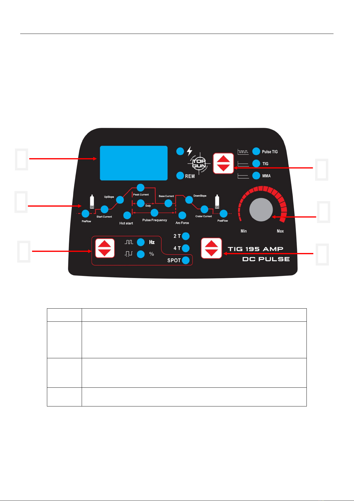
5.1 Operation panel interface & operation instruction
TOPGUN TIG 195 AMP DC PULSE
NOTICE: PICTURES ARE ONLY FOR REFERENCE
1
Current display
2
Control by KNOB 5
TIG MODE shows: pre gas, start current, up-slope, peak current, pulse duty cycle,
pulse frequency, base current, down slope, crater, post gas.
MMA MODE shows: hot start, welding current, force current
3
Spot TIG function button. In spot welding mode, push this button to adjust the spot
welding frequency and spot welding duty cycle.
4
2T、4T、spot function selection button under TIG MODE
1
2
3
4
6
5

USER MANUAL
11
5
Multi function adjustment knob and menu button.
Menu button (long press for 5 seconds to restore factory setting)
In TIG DC 2T/4T mode, you can adjust: pre gas, start current, up-slope, peak current,
down slope, crater, post gas.
In Pulse TIG 2T/4T mode, you can adjust:pre gas, start current, up-slope, peak current,
pulse duty cycle, pulse frequency, base current, down slope, crater, post gas.
MMA MODE shows: hot start, welding current, force current
In TIG/PULSE TIG MODE: adjust spot frequency and spot duty cycle.
6
Pulse TIG/TIG/MMA switching button, long press for 3 seconds to save data. When
turn on the machine, machine will show the data user saved.
I. TIG pulse & TIG no pulse welding instruction:
a) Turn on the machine, the display meter show the value, and exhausting fan start working.
b) Open the gas cylinder valve, adjust the flow to the right volume
c) Remote LED indicator light on, machine output current be controlled by foot pedal; Remote LED indicator light off,
machine output current be controlled by operation interface buttons and knob
d) Could choose “PULSE” & “NO PULSE”, and according to welding requirements, can adjust pulse ratio and pulse
frequency.
e) According to workpiece thickness and welding requirement, can adjust base current and peak current.
f) When press TIG torch button, the solenoid valve start working, the operator can hear the sound of high frequency arcing
discharge, meanwhile, argon gas should flow out from TIG torch nozzle.
g) TIG torch tungsten bar and workpiece distance should be 2.4mm, pressing the TIG torch button, after arcing, the sound
of high frequency arcing discharge would disappear immediately, then the welding work can start.
h) When welding work finish, to protect the welding result, rotate the post-gas knob to the right position.
i) Under “TIG” condition, can choose 2T / 4T according to long time welding and spot welding. Under 2T condition, arcing
current and down slope not work anymore, only welding current can work.
j) Under 4T condition, arcing current start work when press TIG torch button, welding current start work when release TIG
torch button, down slope start work when press TIG torch button again, machine stop working when release TIG torch
button again.
II. MMA function instruction:
a)Turn on the machine, the display meter show the value, and exhausting fan start working.
b)Shift the welding model button to be “MMA”, only “welding current”knob can work
c)According to workpiece thickness, rotate the “welding current” knob to get the right welding current, and then start
working.

USER MANUAL
12
5.2 Welding environment and safety
Working surrounding
a) Welding should be carried out in dry surroundings. The air humidity level should not be higher than 90%.
b) The temperature should be between -10C to 40C.
c) Don’t use the welding machines in sunshine or rain. Keep it off water.
d) Don't use the machines in the places of dust or corrosive air.
e) MIG welding should not be carried out in places with quick air flow.
Safety norms
Protection circuit of over-voltage, over-current and over-heat circuits are designed in the welding machines. It
will stop working automatically when the input voltage, output current or internal temperature exceed the rated
value. But if the machines are excessively used, such as with input voltage higher than the rated, the machine
might be damage. Please pay close attention to the following matters.
a) Keep good ventilation !
The welding machines work with high welding current. Nature air flow can’t reach the requirement of heat
dissipation. So the fans are installed as cooling system to ensure stable performance.
Make sure the ventilation windows are not covered or blocked. The distance between the machines and things
around should not be less than 0.3m. Good ventilation is good for welding performance and operational life.
b) Never over load!
Check the maximum rated current (according to the Duty Cycle chosen). Make sure the welding current is never
higher than the rated value. Over current running will obviously shorten the operation life, even damage the
machine.
c) Never over voltage!
The Input Voltage could be found in technical data diagram. The auto-compensation function will keep the
welding current in the rated range. If the input voltage exceed the permissible value, the machine would be
damaged. Users should take protective measures in advance to avoid it.
d) Make sure earth connected before operation.
On the rear panel of welding machine, a screw for earth connecting would be found. It must be ground
connected with cable whose section is bigger than 6mm2before operation, to avoid accidents caused by static or
electricity leak.

USER MANUAL
13
5.3 Welding problems and resolution
The phenomenon listed below may happen due to relevant accessories used, welding material, surroundings and
power supply. Pleas improve surroundings and avoid these problems..
Arc starting difficulty. Arc interruption happens easily:
a) Examine whether grounding wire clamp contacts with the work pieces well.
b) Examine whether each joint has improper contact.
The output current fails to reach rated value:
The deviation of power voltage from rated value may cause that the output current does no accord with adjusted
value. When the power voltage is lower than rated value, the maximum output current may be lower than rated
value.
The current can not keep stable during operation:
This situation may relate to the following factors:
a) The voltage of electric power network changes;
b) Serious interference from electric power network or other electric facilities.
Gas vent in welds:
a) Examine whether the gas supply circuit has leakage.
b) Examine whether there is sundries such as oil, dirt, rust, paint etc. on the surface.

USER MANUAL
14
6.Daily maintenance and checking
6.1 Daily maintenance
a) Remove dust regularly with dry compressed air. If the welding machine is used in surroundings with heavy smoke
and polluted air, it is necessary to remove dust at least one time one month.
b) The pressure of compressed air shall fall to required level to prevent damage to small components in the
machine.
c) Examine inside electric joints and ensure perfect contact (Especially plugs and sockets). Fasten the loosing joints.
In case of oxidation, remove oxide film with sand paper and connect again.
d) Prevent water from entering into the machine and prevent the machine from getting moist. If any, blow and dry.
Measure the insulation with megohmmeter to make sure it is qualified to use.
e) If the welding machine is not used for a long time, pack the machine in original package and store in dry
surroundings.
f) Every time the wire feeder operates for 300hours, grind the electrical carbon brush and clear up the armature
commutator. Rinse speed reducer, apply 2# Molybdenum Disulfide lubricant to the turbine, whirlpool rod and
bearing.
All the maintenance and testing must be carried out when the power supply is totally cut off. Please make
sure the power is off before opening the closure.
6.2 Daily checking
WELDING POWER SUPPLY
Position
Checking keys
Remarks
Control panel
Operation,conversion and installation of the switch
Check the state of the power indicator light
Lead to unstable arc and wire
sending
Cooling fan
Check if the fan state and the sound is normal or not
Clean the residue and check the
reason and solve it
Power part
Check if there is abnormal liberation and sound
when the power is on
Check if there is smell when the power is on
Whether the outside color change or get warm
Outer parts
Whether the wire feeder pipe is broken,and the
connector is loosen
Whether the outer shell or other connect parts are
loosen

USER MANUAL
15
WELDING TORCH
Position
Checking keys
Remarks
Loophole
If installment fixed, the front distorted
Reason for air hole.
Attach splash or not.
Reason for burning the torch.
(can use splash-proof material )
Electric hole
If installment fixed
Reason of torch screw thread damage
Damage of its head and hole blocked nor
not
Reason of unstable arc and broken arc
Wire sending tube
Check the extended size of the pipe
Have to be changed when less than 6mm, when
the extended part too small, the arc will be
unstable.
Wire diameter and the tube inner
diameter match or not
Reason of unstable arc, please use the suitable
tube.
Partial winding and extended
Reason of poor wires sending and unstable arc,
please change.
Block caused by dirt in the tube, and the
remains of the wire plating lay.
Reason of poor wire sending and unstable arc,
(use kerosene to wipe or change new one.)
Wire sending tube broken O circle wear
out
Pyrocondensation tube broken, change new
tube. Change new O circle
Gas bypass
Forget to insert or the hole blocked, or
different factory component.
May lead to vice (splash) because of poor gas
shield, torch body get burned (arc in the torch),
please handle.

USER MANUAL
16
7. Trouble shooting and fault finding
Notes: The following operations must be performed by qualified electricians with valid certifications. Before
maintenance, you are suggested to contact local distributor to verify qualification.
Malfunctions
Solution
The meter show nothing;
Fan does not rotate;
No welding output
Confirm the power switch is on.
Power supply available for input cable.
Check if the three phase commute bridge is damaged.
There is malfunction occurs in the supplementary power source
on control board (contact dealers).
The meter shows;
Fan works normally;
No welding output
Check if all the sockets in the machine are connected well.
There is open circuit or badness of connect at the joint of output
terminal.
The control cable on the torch is broken off or the switch is
damaged.
The control circuit is damaged.(contact to dealers)
CABLE
Position
Checking keys
Remarks
Output cable
Wearing-out of the cable insulated material
Cable connecting head naked (insulation damage), or
loosen (the end of power supply, and cable of main
material connecting point)
For life security and stable welding,
adopt suitable method to check
according to working place
Simple check daily
Careful and in-depth check on
fixed period
Input cable
If the connection between the plug and the power socket
is firm
If the power input end cable fixed
If the input cable is worn out and bares the conductor
In case of leakage and to ensure
safety, please do perform daily
checking
Earth cable
If the earth cable that connects the main part is broken and
connects tightly
Position
Checking keys
Remarks

USER MANUAL
17
the meter shows;
Fan works normally;
Abnormal indicator lights.
It might be over-current protection, please turn off the power
switch; restart the machine after the abnormal indicator light
winked.
It might be overheating protection, please wait for about 2-3
minutes until the machine renew without turn off the power
switch.
It might be multifunction of inverter circuit. (contact dealers)
Initial problems diagnose
Abnormal Items
Area and Item to be Inspected
and Maintained
No arch Arc Starting
No Gas out
No Wire Feeding
Bad Arc Ignition
Unstable Arc
Dirt on Edge of Weld Seam
Wire Stick to Parent material
Wire Stick to Conductive Tip
Blowhole Formed
Distribution Boxes (Input
Protection Devices)
Turn on power supply or not?
Fuse burnt out
Connection joint loose
〇
〇
〇
〇
〇
〇
Input Cable
Examine whether the cable is
cut off.
Connection joint loose
Over heat
〇
〇
〇
〇
Welding Power
Operation
Turn on power supply or not?
Phase Lacking
〇
〇
〇
〇
〇
〇
〇
〇
Gas Cylinder and Gas
Regulator
Turn on gas supply
Residual Amount of Gas in the
cylinder
Set value for flow
Connection joint loose
〇
〇
Gas supply hose (the
whole line from the high
pressure cylinder to the
weld gun)
Connection joint loose
Gas hose damaged
〇
Table of contents
Other TOP GUN WELDING Welding System manuals


Popular Welding System manuals by other brands


Thermal Dynamics
Thermal Dynamics PakMaster 100 XL plus operating manual

ESAB
ESAB THERMAL DINAMICS CUTMASTER 60i operating manual

Taurus
Taurus MIG-350I Operation manual

Ter Welding
Ter Welding Smart Welder MMA 140 user manual

ESAB
ESAB Caddy Tig 2200i AC/DC instruction manual

Thermal Dynamics
Thermal Dynamics AUTO-CUT 30 O2 operating manual

Miller
Miller EnPak A30 GBW owner's manual

Magmaweld
Magmaweld Monostick 160i user manual

Lincoln Electric
Lincoln Electric 11779 Operator's manual

EWM
EWM Tetrix 200 MV Comfort puls 5P TG operating instructions

EWM
EWM alpha Q 330 Progress puls MM TKM operating instructions

ESAB
ESAB A6 TFD1 Simplified service manual