TOP NOTCH SHOESTRING User manual

TOP NOTCH PRODUCTS
SHOESTRING
Top Notch Products Company
PO Box 1051
Goodlettsville, TN 37070
Tel 615-866-4327
Fax 615-523-1154
Email - [email protected]
www.topnotchkits.com
ASSEMBLY MANUAL

WING ASSEMBLY
□ 1. Use a straight edge to align the false leading edge (FLE) with
the plan. Glue a pinning tab to the front of each stand off as
shown in the photo. Secure each tab to the building board
with a couple of crossed pins. Assure that FLE is at 90º to the
building board.
□ 2. Assemble W7 and W7-A and W8 and W8-A. Note the correct
orientation of the A components, they should be on the
outside of the servo bay. A good way to avoid problems here
is to assemble both sets at the same time. Just make sure you
assemble two sets that are opposite each other. Then select the
set for the wing half you are working on.
Builders note:
When assembling laser cut components it is important to remember that the accuracy of the laser cut part
may exceed that of the tolerances maintained by the material. This can be caused by milling tolerance
issues, humidity and other factors in the manufacturing processes. When assembling these components
make sure that all parts align exactly with their respective tabs and slots. If they don’t seem to t, go back
and locate the problem. Do not force the parts. When they are correctly aligned they will practically fall
together.
When assembling notch and tab parts you will be required to dry t many parts before gluing them.
This is because many of the internal parts require some movement of other parts to get tabs and slots
into position. Do not glue parts until directed to do so. In the event that a part is missed, you may have
to remove the tab to get it into position. Lets build this puppy but put your glue away for now.
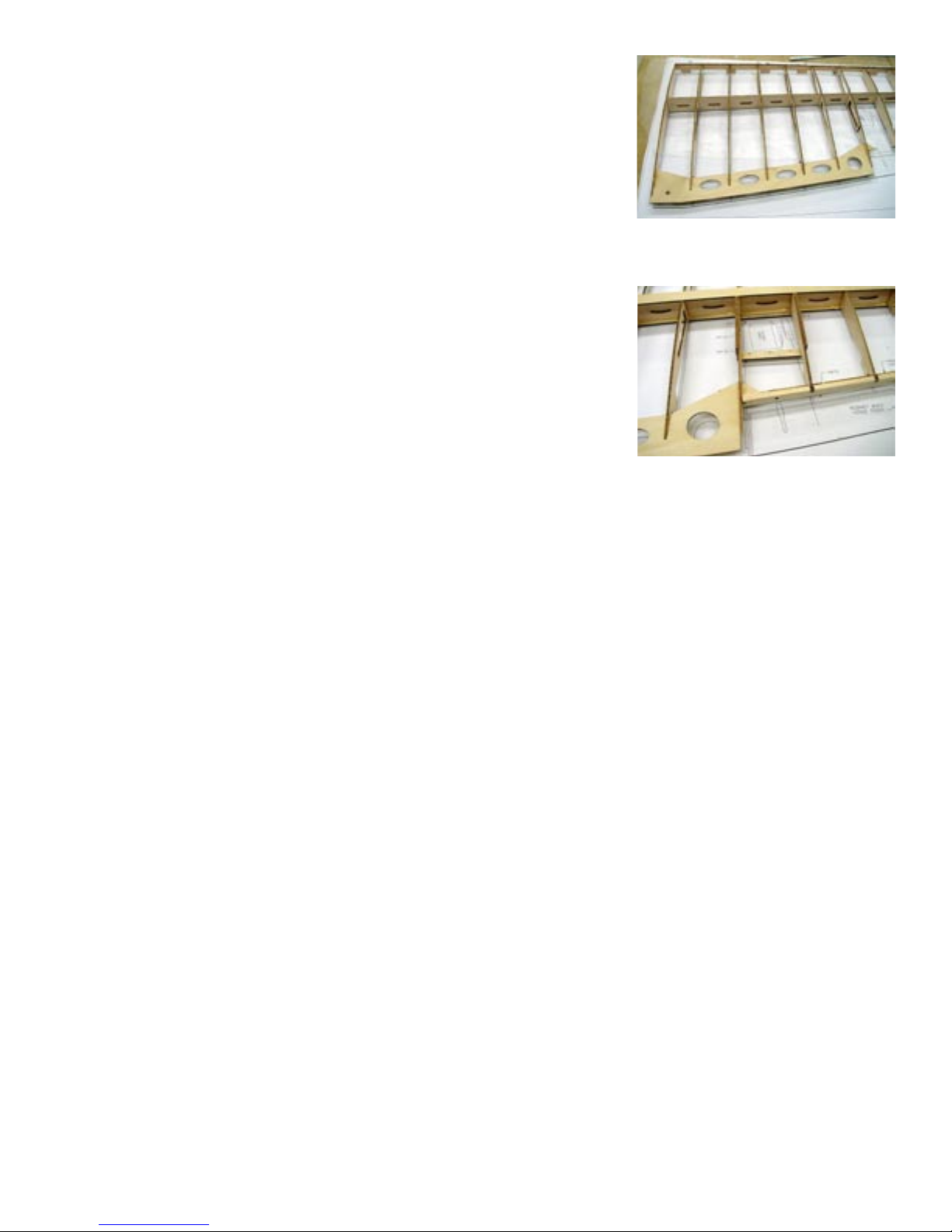
□ 3. Place the bottom sheer web (SW-B) on the bench with the slots up.
Slide each rib into its appropriate slot. Note that the rst full slot will
be for W2.
□ 4. Now install the top sheer web (SW-T) onto this assembly until it
will align with SW-B. Hold the top and bottom of the sheer webs in
alignment at the root and tack glue them with a small amount of thin
CA. Now do the same at the tip of the sheer web. You should now
have all ribs except W-1 captive on the sheer web assembly.
□ 5. Slide each rib tab into the appropriate notch in the false leading edge
(FLE).
□ 6. Install a wing gusset (WG) at the leading edge of rib W3, W7 and
W11. Make sure the ribs are seated in the leading edge and the ribs
are aligned with the gussets.
□ 7. Chamfer the edges of the fore and aft wing tip braces (WT-F & WT-
A) so they will seat at the intersection of the sheer web and W12.
□ 8. Install the ply wing tip. It will t into slots in the leading edge and
sheer web tip and tabs will interface with W11.
All ribs have been installed into the bottom
sheer web. Top sheer web is lying on top
of the assembly and is ready to be installed
next.
Pin tabs are used to secure FLE to the building
board.
□ 10. Install the aileron bay trailing edge (ABTE). A small amount of extra
material has been provided to allow sanding the ends to parallel W7
and W12 for a ush t. The end marked “R” is the root end. Use a
piece of 1/8” music wire through the hinge holes to align the hinge
blocks (HB) and glue them at this time. First tack glue them, then
remove the piano wire pin and the then complete gluing them with
thin CA.
□ 11. Here comes the “G” word. At this point you have the entire
superstructure of the wing dry t assembled with a few minor
exceptions. Get your glue out. One note here, when building like this
it is easy to loose track of what has been glued and what has not. Best
to be systematic about it. Start with the rib leading edges, at each step
along the way check the assembly for square. Before beginning place
some weight on the aft portion of the wing rib to be sure they are in
contact with the building board. Yet another note, when gluing the
sheer webs, make sure that they are perfectly ush top and bottom.
Use some scrap 3/32” balsa to shim them up at every other bay. Once
ush, apply thin CA into the glue ports cut into SW-T. Hold the two
sheer webs in close contact and apply just enough CA to tack them at
this time.
□ 12. You are now ready to install the top spar ange. Note that the spar ange has a top and a bottom. Be sure
to install it so that the root end aligns with W1, if it doesn’t align, ip it over. Use aliphatic resin or slow
CA to glue this. Keep the weight on the aft rib sections to assure the ribs are seated on the building board.
Apply glue to the entire length of the spar web and to each rib ange notch. After installing, weight it with
a straight edge until cured.
□ 9. Install the 1/16” ply wing trailing edge. It must tip into the slot in W7
and then slide forward into the slots at the trailing edges of ribs W2,
W3, W4, W5 and W6. Tabs will engage it into rib W1.
The 1/16” ply trailing edge keys into all
wing ribs. It must tip into rib W-7, then
slide forward into remaining ribs.
Aileron bay trailing edge (ABTE) keys
into all wing ribs. Note that in this
photo the aileron servo mount rails have
already been installed. You will get to
those later.
□ 13. When the glue has cured, remove the weights and pins and remove the assembly from the building board.
DO NOT remove the pinning tabs and stand off’s at this time. Lay the assembly upside down and install
the bottom spar ange in the same manner as you did the top one. Leave the leading and trailing edges
oat above the plan.
□ 14. The next step is to apply the top wing sheeting. Before that can be done however we need to plane the false
leading edge to contour with the wing ribs. Plane the aileron bay trailing edge to contour as well. Also sand
the trailing edge ply and wing tip ply somewhat to contour to increase glue land along these edges. Each
wing skin will require four 4” x 36” sheets of 1/16” balsa. Prepare four 1/16” x 15” x 36” wing skins.
□ 15. Place the assembly back on the building board topside up and pin the pin tabs to the board. Trim one of the
wing skins to about 1/2” oversize. You may have a preferred method but I will tell you what I did and you
can decide. Using aliphatic resin glue, apply a liberal bead of glue to all ribs and on the top spar ange,
leave the last two inches of the top spar ange at the root end without glue. This area will be glued later as
part of the spar joiner. Leave the leading edge and trailing edges dry. Place the wing skin over the assembly
and weigh it down with sand bags, shot bags, magazines or what ever you use to assure that the skin is kept
in contact with all ribs until the glue has set. This will take about 20 minutes. After the aliphatic resin has
set, remove the assembly from the building board, snap off all the stand off’s and pinning tabs. Temporarily
force the top sheeting into contact with the ply wing tip and mark the edge with a pencil line.

□ 16. Place the assembly upside down on the bench and put pressure along the leading edge to force the sheeting
into contact with the leading edge. Apply thin CA along the entire leading edge and let cure. Apply pressure
along the trailing edge and apply CA there as well. Trim the sheeting to within about ” of the ply wing
tip, DO NOT glue the wing tip sheeting at this time.
□ 18. Plain all bottom leading and trailing edges to contour in preparation
for the bottom wing sheeting. A set of three jigs is supplied to support
the wing while installing the bottom sheeting. Glue some 2” pieces
of ” x ” balsa into the slots provided to support the jigs. Place
these ” balsa jigs at W2, W7 and W12. Apply a liberal bead of glue
to the bottom of all ribs and the bottom spar ange except where
noted. Once again do not glue the last two inches of the spar ange
to accommodate adding the spar joiner. Also omit gluing around the
servo bay, this will make it easier to remove material for the servo
mount and will be glued with thin CA after the opening has been cut.
□ 17. Install the two 3/32” ply servo mount rails. Use the 1/16” ply servo mount to align the screw holes for a
better t. You can screw the rails to the cover and then glue assembly into position. Remove the screws
and cover when cured.
Wing assembly suspended on the rib jigs
at W2, W7 and W12. These jigs will sup-
port the wing assembly while the bottom
sheeting is being installed.
□ 20. Assembly of the wing halves is a two-step process. First install two 1/4” x 1” dowels into the holes provided
in the ” lite ply wing joiner rib. This rib will not only align the wing halves but also support the ” wing
mounting dowel. It’s a good idea to use a piece of ” carbon ber rod for this component. Assemble the
wing halves with the ply wing joiner rib. Prop one wing tip up 4” at W12 for correct dihedral.
□ 21. Use one of the 1/64” ply spar joiners as a template to mark and remove the wing sheeting from the top and
bottom spar anges at the wing joint. Use slow setting Epoxy or nishing resin and lay in four of these
1/64” ply joiners with a liberal application of Epoxy between each one. Use plenty of pressure to keep the
ply joiner ush with the top of the balsa sheeting. When cured, turn the wing over and repeat the process
on the bottom spar ange.
□ 22. Glue on the wing bolt plate.
□ 23. Note that the aileron is laminated from three pieces. The bottom piece is 3/16” balsa, the center section is
assembled from 3/32” balsa and 3/32” ply and the top is 1/4” balsa. The ply aileron horn is glued into the
3/32” balsa center section rst. These parts are provided with a 1/8” pinning hole at each end. Use a piece
of 1/8” music wire or the shank of a 1/8” drill bit in each hole to align the parts when laminating them
together. Note the stack order of the parts and be sure to make a left and a right.
□ 19. After curing, use the same technique to glue the leading and trailing
edges with thin CA. Trim the tip as you did the top skin and then
starting at the center in line with the spar web, use thin CA to glue
both skins to the ply tip at the same time. This will help keep both sides even. Glue on the ” leading edge’s
and plane and sand to shape.
□ 24. A great tool for marking and shaping the ailerons is three 2” sections of 1/8” music wire rounded at each
end. Place these in the hinge holes in the aileron and then temporarily install onto the wing. These will hold
the aileron ridged while you mark the edges of the aileron assembly for shaping.
□ 25. Glue the two 1/64” ply aileron cable opening liners about 1” behind the main spar and about 1” out from
the joiner rib. After gluing, remove the balsa from the center to allow access for your servo cables.
This concludes assembly of the wing.

□ 1. Assemble the elevator core (EC) from two parts. This and the following steps are best done over a sheet
of parchment paper. This material is available in your local grocery store in the baking department. Hey, if
chocolate chip cookies won’t stick to it, glue doesn’t stand a chance. I digress.
□ 2. With the core sheet at on the bench, install all split ribs starting
from S1. Hold the core sheet at while applying thin CA.
Stabilizer assembly
□ 13. Assemble the elevator sections. Note that one elevator core also contains a ply plate to attach the horn to.
Keep this in mind when hinging to get it on the desired side.
□ 3. When all ribs have been installed, install the trailing edge. Hold
the trailing edge in place with the straight edge of a ruler or other
straight edge while applying CA as shown in the photo at the right.
This will keep the assembly straight.
□ 4. Turn the assembly over and install all ribs on the opposite side.
Apply nger pressure to the ribs to keep the assembly at and
make good contact with the parts.
□ 5. Assemble both stabilizer skins and sand out any irregularities. For the next step you will need some spring
type cloths pins or other means of providing even pressure along both leading edge halves. Cloths pins work
best.
□ 6. Use a straight edge or a straight board on the bench to butt the stabilizer skin up against for the next step. If
you can just butt the assembly up against the straight edge and then bring it into contact with the skins the
next step is much easier to do. Place one of the skins on the bench with the trailing edge butted up against
the straight edge. Now apply aliphatic resin glue to all the ribs on one side of the stab assembly. Next apply
a liberal bead of thick CA along the trailing edge. Flip the assembly over and but it up against the straight
edge and then bring one half down into contact with the skin. Apply pressure until the CA sets and then rock
the assembly over and apply pressure to the other half.
□ 7. Turn the assembly over immediately and repeat the process for the opposite side.
□ 8. Now apply a cloths pin about every inch along the leading edge check the assembly for straightness before
the next step.
□ 9. Hold the assembly on end and apply thin CA to the leading edge at the tip. Allow it to run down the leading
edge between the sheeting until it reaches the center. Now ip the assembly over and repeat the process for
the other half. You can now glue the tip sections by just squeezing them together and applying CA. This
concludes the assembly of the stab section. Trim and sand to nish.
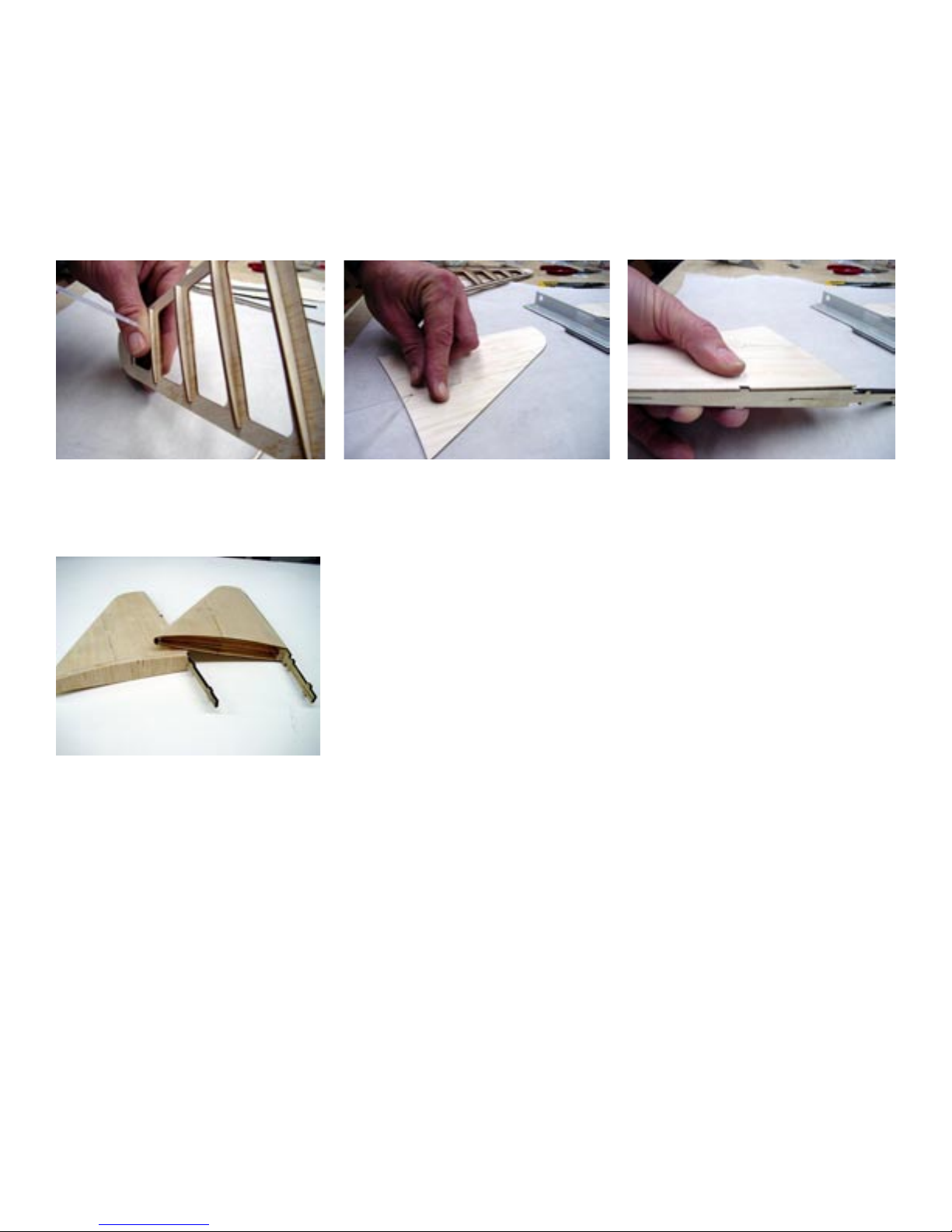
Fin Assembly
□ 1. Use the same technique as the stabilizer, lay
the core sheet at on the bench and install all
the split ribs on one side. Install the trailing
edge with a straight edge as before. Trim the
corners off of the leading edge of each rib to
align with the leading edge and install the
leading edge.
Photo at right shows all n components .
□ 1. Assemble the three laminations that will comprise the rewall. If you have your motor mount, now is a good
time to locate and drill the mounting holes and install the blind nuts. The centerline and the offset thrust line
are indicated on the rewall front for this purpose.
□ 2. Turn the assembly over and repeat the process on the reverse side.
□ 3. Glue on the 1/8” ply trailing edge taking care to align it with the balsa trailing edge.
□ 4. Assemble the two-piece n skins and install.
□ 5. Use some scrap 1/16” balsa and glue two laminations to the bottom of the skins to stiffen the sheeting at the
bottom.
□ 6. Carve and sand to shape. Assemble the rudder from three ” laminations. Note that the center lamination
also contains a ply horn mount, as did the elevator.
Here the second half of the split ribs are
being added to the stabilizer core sheet.
Note that this part of the construction is
done in the air.
Here the laser cut n sheeting is being
assembled over parchment paper with
thin CA.
Here the n sheeting is being installed.
Note the tab on the rudder post will
provide exact positioning.
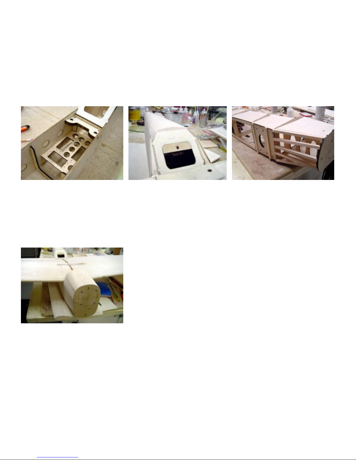
Fuselage
A couple of notes on the fuselage construction
The rewall has 3.5º of right thrust built in. This will require that the motor be mounted offset to the left
side of the airplane so the spinner will center. This requires that the fuselage sides be slightly different
and so are marked left and right. Be sure to note this.
After assembly add two layers of scrap
1/16” balsa to the bottom of the assem-
bly as shown in this before and after
example.

□ 2. Assemble the two fuselage sides with the former notches in the sides. Note that there are two sets of fuselage
sides. One set has all the notches to accept the formers in it and the other set is marked skins. Put the set
marked skins aside for use later. Also note that the sides are marked Left and Right. The two sides are
slightly different and must be used in their appropriately marked locations. They will set the thrust offset
in the rewall. Glue on the aft section of each fuselage side. Next, using the pinning holes at the front and
back of the 1/32” ply doublers, glue on the doublers using the following method. Place the fuselage side on
the pins and test t the doublers by sliding it down the pins. Remove the doublers and ip it over. Apply a
liberal bead of thick CA to the following areas. All areas of the forward solid area (the area without the glue
port holes cut into it), along the wing saddle, at each former and all of the aft solid area. The area with the
holes cut in it will be glued later with thin CA. Now slide the doubler down the pins and press into contact
with the fuselage side. As soon as the two parts have xed, remove the pins and apply pressure along the
entire doubler. Use a straight edge to apply pressure to the doubler and liberally apply thin CA through all
the glue portholes.
Some fuselage subassemblies. Note the
addition of 1/4 X 1/8 hardwood behind the
screws on the servo tray. Pinning holes in
the wing bolt plate provide perfect align-
ment when laminating the two parts. Note
that the #1/4-20 blind nuts have been
trimmed.
Here the fuselage construction has begun,
showing the laminated rewall, lami-
nated F2& F2-A as well as the tank oor.
These components will set the angle of
the rewall at 3-1/2° of right thrust. Add
triangle stock for additional strength.
Again the use of pinning holes provided
in the parts make accurate alignment of
the fuselage doublers fool proof. The
holes in the 1/32” doubler are for apply-
ing glue as well as lightening.
□ 3. Lay one fuselage side on the building board and using Epoxy, glue in F4-A. Use a square to assure it is at
90º to the side.
□ 4. Cut a piece of scrap stock 3-1/2” long to be used as a tail spreader in the next step. Apply Epoxy to the
remaining side of F4-A and install the second fuselage side. Use the spreader stick in the tail section to keep
the fuselage sides parallel until the Epoxy has cured. Also use a square to assure that both fuselage sides are
parallel at the elevator saddle.
□ 5. Assemble the laminated wing bolt plate from one 1/4” lite ply and one 1/16” AC ply part. Press in the #1/4-
20 blind nuts, the nut anges will require trimming.
□ 6. Now install Former F-5, the wing bolt plate assembly and the servo tray with Epoxy. Note that all these
parts interface with each other.
□ 7. Install F-6, F-7 & F-8 and the tail post (TP); note that the tail post is recessed 1/8” to leave room for the
vertical n post.
□ 8. Install F-4 with Epoxy.
□ 9. Install the F-3 assembly with Epoxy.
□ 10. Install the rewall assembly and the tank oor with Epoxy. After curing, add 3/8” triangle stock along both
sides and the rewall as well as along the tank oor and rewall.
□ 11. Assemble and install the hatch hold down block (HH) and glue to F-5A.

□ 12. Install F-5A. Use some 1/4” triangle stock behind F5-A for added strength.
□ 14. Laminate GMA and GMB, once again using the pins for alignment. Drill and install the blind nuts for the
landing gear and then install into the fuselage using Epoxy, add 3/8” triangle stock on all four sides of the
GM assembly.
□ 24. Use a sheet of 3/32” balsa to sheet the aft bottom section from the landing gear to the tail post. Run this
material cross grain.
□ 13. Add the 3/8” triangle stock to the top from F5-A to F8.
□ 15. Install 3/8” triangle stock along the fuselage bottom from F4 to F8.
□ 17. Install the ve ” square stringers, top and bottom between the rewall and F3.
□ 16. Install the 3/16” stabilizer saddle doublers (SD).
□ 19. Install the wing saddle doubler (WSD). Note that WSD is has two sections to it; there is a second layer to
it at the aft end. Plain this second layer of WSD to taper ush with FO-5 to ush feather at FO-4A.
□ 18. Install the outer formers, FO-3, FO-4, FO-4A, FO-5A, FO-5B, FO-6, FO-7 and FO-8.
□ 22. It’s a good idea to sand the out sides of the fuselage skins before installing. It’s a lot easier to do this while
they can be laid at on the bench.
□ 21. Before adding the fuselage skins, check your fuselage assembly. You may want to sand or plain the
edges of the assembly to provide more glue land for the skins at the edges. A couple passes with 120 grit
sandpaper should do the job.
□ 20. Assemble the outer fuselage skins. Once again there is a left and a right. The outer fuselage skins are
assembled from three pieces.
□ 25. Use a sheet of ” x 4” balsa to sheet the top fuselage section from F5-A to the stabilizer saddle.
□ 23. When installing the fuselage skins it is helpful to have a piece of 5/16” square stock to insert into the
pushrod exit to help keep things aligned at the aft end. There is a notch at the front that will engage a tab
on the rewall assembly to align the front. Apply a liberal bead of aliphatic resin glue to all FO formers
except the top portion of FO-3 from the wing saddle to the top. This section will be glued in a later step.
Apply a liberal bead of thick CA to the rewall and along the wing saddle. Apply a second application to
the rewall to make sure there is plenty of adhesive. Place the fuselage skin into position using the tab at
the front and the push rod exit slot at the aft end. Align the wing saddle and press into contact until the
thick CA cures. Do the same with the rewall area. Now using nger pressure, move along the top of the
fuselage and apply thin CA to the remaining fuselage skin. Move to the bottom of the fuselage skin and
repeat this process along the bottom. When completed, trim away the section of FO-8 that crosses the push
rod exit slot.
□ 26. The hatch is constructed on the fuselage with the wing in position. Bolt the wing on and then place a piece
of waxed paper at F-3 and F5-A to prevent adhesive from making the hatch permanent. Install two 1/8”
dowels into FH-1. Round the ends so they will easily enter the holes in F-3. You will need to remove some
material from the bottom of FH-1 to get a good t.
□ 27. Pin FH-5 in position over F5-A with the waxed paper in between them, install
□ 28. Measure back from F3, 3-1/2” and 9-1/4” and place a mark on top of the wing at these locations. FH-2 and
FH-3 will go at these locations.
□ 29. Test t HA-1 on both sides of the fuselage. You may need to trim or sand a slight angle at the bottom to
accommodate the wing dihedral. When satised with the t, glue HA-1 to FH-1 and FH-5.
□ 30. Install FH-2 and FH-3 at the locations marked earlier.

□ 1. Place the stabilizer in the stabilizer cradle and check the t and incidence angle. The stabilizer should t
snugly in the saddle. Locate and mark the exact center of the trailing edge and align that with the center of
the tail post.
□ 33. The hatch is retained by the two 1/8” balsa dowels at the front and a single #6-32 x 1” bolt at the aft end.
You will have to attach the hold down blocks and drill and tap these at this time. You can mark the location
of the hatch hold down bolt in the bottom of the 1/4” top by backing the bolt out and then pressing the top
down on top of it to leave a mark.
□ 32. Remove the hatch assembly from the fuselage and plain and sand the sides (FH-1’s) and the triangle stock
at to receive the 1/4” hatch top for a good glue joint.
□ 31. Install the 3/8” triangle stock on both sides.
□ 34. Use the aft end of the hatch assembly as a guide to angle trim the end of a piece of 1/4” x 4” balsa, then
glue in place on the hatch top.
□ 35. Bolt the hatch assembly back in place and plain and sand to shape. A good method for getting a nice joint
between the hatch and the fuselage is to take a piece of waxed paper and cut pieces to t against F-3 and
F-5 and about ”oversized. Next mix a batch of Sig Epoxo-Lite and butter both ends of the hatch around
and the edges so that when the hatch is bolted in place the Epoxo Lite will squeeze out to form a tight t.
Now bolt the hatch in place until the Epoxo-Lite cures and then remove and sand to shape.
□ 36. The cheek cowls are composed of ve parts and will later be cut to allow part of them to be xed to the
hatch while the major part of them will be attached to the fuselage. Note that CCL designated parts are for
the left cheek cowl and those marked CCR are for the right cowl, I will describe the assembly of the left
cowl. Start by gluing CCL-1 to CCL-3. Next add CCL-2 to the bottom of this assembly. Now add CCL-4.
Trim this assembly until you get a reasonably good t to the fuselage. With this assembly in place on the
fuselage, add CCL-5 to the top of this assembly. Trim it for a good t and then glue CC-5 to the cheek cowl
assembly. Repeat this for the right cheek cowl.
□ 37. Place the cowl ring on the rewall with two 1/8” dowels in the holes supplied in the cowl ring. NOTE:
for a good t you may want to use short sections of 1/8” brass tubing instead of wood doweling. With the
cowl ring in place on the rewall, drill holes for the retaining screws, then remove the cowl ring. Trim
the berglass cowl about 3/16” to provide a straight clean edge. Place the cowl ring on the bench with the
labeled side up and place the glass cowl over it until the ring is nested inside the glass cowl. If the t is
irregular, sand the inside of the cowl until it is achieved, then Epoxy the cowl ring to the cowl.
□ 2. Square the stabilizer by measuring from the exact top center of the rewall to the trailing edge at both sides
of the elevator tips.
□ 38. Place the cowl onto the rewall and screw into place. Bolt the wing and the hatch to the fuselage and then
place the two cheek cowls in position and mark the outline of the cowl on the front of the cheek cowl
assemblies. Now trim and sand the cheek cowl assemblies to shape. Draw a line on both cheek cowls in
line with the front of the rewall. Also draw a line from the front of the wing leading edge to intersect with
this line. This will be the parting line for the cheek cowls and the smaller portion will be glued to the hatch
assembly while the main portion will be glued to the fuselage. Cut the two sections apart and then glue to
their respective locations. Use the same technique with a sheet of waxed paper to mate the two sections of
cheek cowl.
STAB INSTALLATION
□ 3. Next check that the stabilizer is at 90º to the fuselage sides.
□ 4. Glue the stabilizer to the fuselage with Epoxy. The elevator sections will be added after covering.
□ 3. When satised with this, Epoxy into position. The rudder will be added after nishing.
□ 2. When satised with the t, check the n for square (90º to the stabilizer) and correct alignment (directly on
and aligned with the fuselage center line).
□ 1. The vertical n ply trailing edge is tabbed to t into notches provided in the fuselage. It should rest snugly
on the top of the stabilizer. If it does not add or remove some balsa from the bottom of the n.
VERTICAL FIN INSTALLATION
The wing bolt plate assembly and the servo
tray will square the entire fuselage as-
sembly when the tabs enguage the notches
provided in the fuselage sides.
The hatch hold down block (HH) has
been installed and is visable through the
lightening hole in F5-A. Use a #6-32 tap
in the plywood block and then harden it
with thin CA.
The outer formers have been added to
the fuselage sides and the skins are about
to be added. Both the top and bottom
forward sections are sheeted with 3/32”
balsa over the 1/4” sq. stringers.
The hatch is constructed on the wing with
the wing in position on the fuselage. Note
the 1/64” ply wing joiner. Next the cheek
cowels will be added and shaped to match
the berglass cowl.
Table of contents


