manuals.online logo
Brands
  1. Home
  2. •
  3. Brands
  4. •
  5. Costway
  6. •
  7. Toy
  8. •
  9. Costway TY327934 User manual

Costway TY327934 User manual

This manual suits for next models

1

Other Costway Toy manuals

Costway TY556631 User manual

Costway

Costway TY556631 User manual

Costway TY578067 User manual

Costway

Costway TY578067 User manual

Costway OP70505 User manual

Costway

Costway OP70505 User manual

Costway TQ10089BL User manual

Costway

Costway TQ10089BL User manual

Costway TY579445 User manual

Costway

Costway TY579445 User manual

Costway TY327903 User manual

Costway

Costway TY327903 User manual

Costway TY327902 User manual

Costway

Costway TY327902 User manual

Costway TP-10078WH User manual

Costway

Costway TP-10078WH User manual

Costway UY10060 User manual

Costway

Costway UY10060 User manual

Costway TY322392 User manual

Costway

Costway TY322392 User manual

Costway Benz scooter truck User manual

Costway

Costway Benz scooter truck User manual

Costway TP10159 User manual

Costway

Costway TP10159 User manual

Costway TY507997 User manual

Costway

Costway TY507997 User manual

Costway TQ10076 User manual

Costway

Costway TQ10076 User manual

Costway TY342975 User manual

Costway

Costway TY342975 User manual

Costway TQ10150 User manual

Costway

Costway TQ10150 User manual

Costway TS10098 User manual

Costway

Costway TS10098 User manual

Costway TQ10092 User manual

Costway

Costway TQ10092 User manual

Costway TP10033 User manual

Costway

Costway TP10033 User manual

Costway TY325133 User manual

Costway

Costway TY325133 User manual

Costway NP10816 User manual

Costway

Costway NP10816 User manual

Costway TP10064 User manual

Costway

Costway TP10064 User manual

Costway HW67588 User manual

Costway

Costway HW67588 User manual

Costway honey joy TY327755 User manual

Costway

Costway honey joy TY327755 User manual

Popular Toy manuals by other brands

FUTABA GY470 instruction manual

FUTABA

FUTABA GY470 instruction manual

LEGO 41116 manual

LEGO

LEGO 41116 manual

Fisher-Price ColorMe Flowerz Bouquet Maker P9692 instruction sheet

Fisher-Price

Fisher-Price ColorMe Flowerz Bouquet Maker P9692 instruction sheet

Little Tikes LITTLE HANDIWORKER 0920 Assembly instructions

Little Tikes

Little Tikes LITTLE HANDIWORKER 0920 Assembly instructions

Eduard EF-2000 Two-seater exterior Assembly instructions

Eduard

Eduard EF-2000 Two-seater exterior Assembly instructions

USA Trains EXTENDED VISION CABOOSE instructions

USA Trains

USA Trains EXTENDED VISION CABOOSE instructions

Modellbau Laffont Z1601 Assembly instructions

Modellbau Laffont

Modellbau Laffont Z1601 Assembly instructions

NOCH 12905 instruction manual

NOCH

NOCH 12905 instruction manual

Eduard Ki-61-Id quick start guide

Eduard

Eduard Ki-61-Id quick start guide

Viessmann Vollmer 45616 Mounting instruction

Viessmann

Viessmann Vollmer 45616 Mounting instruction

Vollmer 42004 Mounting instruction

Vollmer

Vollmer 42004 Mounting instruction

Phoenix Model CLASSIC-EP instruction manual

Phoenix Model

Phoenix Model CLASSIC-EP instruction manual

H-KING Sopwith Camel British WW1 Fighter instruction manual

H-KING

H-KING Sopwith Camel British WW1 Fighter instruction manual

MODSTER Predator 4x4 Crawler user manual

MODSTER

MODSTER Predator 4x4 Crawler user manual

DHK Hobby 8136 User instruction manual

DHK Hobby

DHK Hobby 8136 User instruction manual

THUNDER TIGER Raptor 50 V2 kit manual

THUNDER TIGER

THUNDER TIGER Raptor 50 V2 kit manual

Timberkits Skateboarder instructions

Timberkits

Timberkits Skateboarder instructions

Hangar 9 Funtana 125 Assembly manual

Hangar 9

Hangar 9 Funtana 125 Assembly manual

manuals.online logo
manuals.online logoBrands
  • About & Mission
  • Contact us
  • Privacy Policy
  • Terms and Conditions

Copyright 2025 Manuals.Online. All Rights Reserved.

EN DE FR ES IT PL
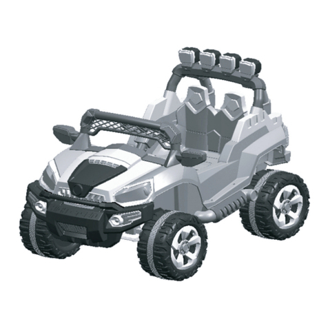
Battery Powered Kids UTV Ride On
TY327934
Please read all instructions carefully and keep it for future reference.
Warnings:
Attention! Use it with protective equipment.
Attention! Not use it in the traffic.
Attention! The product is not suitable for the children under 3 years.
General Warnings:
The product must be installed and used under the supervision of an adult.
Read through each step carefully and follow the proper order.
Remove all packaging, separate and count all parts and hardware.
Please ensure that all parts are correctly installed, incorrect installation can lead to a danger.
We recommend that, where possible, all items are assembled near to the area in which they
will be placed in use, to avoid moving the product unnecessarily once assembled.
Ensure a secure surface during construction, und place the product always on a flat, steady
and stable surface.
Please use the product carefully, as the product requires great skill, avoid accidents by the
user or others, by fall or collision.
Please wear suitable protective equipment during use, e.g. protective helmet, gloves, knee
pads, elbow pads etc.
Owner’s Manual
with Assembly Instructions
Styles and colo(u)rs may vary.
Made in China.
The owner’s manual contains important safety information as well as assembly, use and
maintenance instructions.
The Ride-on Car must be assembled by an adult who has read and understands the
instructions in this manual.
Keep the package away from children and dispose of properly before use.
Keep this manual for future reference.
02 03
Battery
Charger
12V10AH*1
12V1000mA
Suitable age:
Load Capacity:
Speed:
Size of car:
Power way:
Charge time:
37-96 months
Under 66lbs.
3-6 km/h
With roof 46.5” x 30” x 41”
Charging type
8-12 hours
About Your New Ride-On │ 1
SPECIFICATIONS:
On the purchase of your new Ride-On.
This ride-on will provide your child with many miles of riding of enjoyment. To
help assure you and your rider a safe ride we ask you to please read this manual
carefully, and keep it for future reference.
Follow the recommendations in this manual, they are designed to improve the
safety and operation of your ride-on car and it’s rider.
The following safety hazards may result in serious injury or death:
• Never leave child unattended. Direct adult supervision is required. Always keep
child in view when child is in vehicle.
• To reduce the risk of injury, adult supervision is required. Never use in roadways, near motor
vehicles, on or near steep inclines or steps, swimming pools or other bodies of water, always
wear shoes, and never allow more than 1 rider.
• Never use in unsafe conditions such as snow, rain, loose dirt, mud, sand, or gravel,
otherwise may result in an unexpected accident such as tipping over, and could
damage the electrical system or battery
• Not to be used in traffic.
• This toy should be used with caution since skill is required to avoid falls or
collisions causing injury to the user or third parties.
• This toy is unsuitable for children under 36 months due to its maximum speed;
Maximum user weight is 66LBS.
• This toy has no brake.
User Notice │ 2
WARNING!
SAFETY
●Non-rechargeable batteries are not to be recharged.
●Rechargeable batteries are to be removed from the toy before being charged.
●Rechargeable batteries are only to be charged under adult supervision.
●Different types of batteries or new and used batteries are not to be mixed.
●Batteries are to be inserted with the correct polarity.
●Exhausted batteries are to be removed from the toy.
●The supply terminals are not to be short-circuited.
BATTERY INFORMATION
• CHOKING HAZARD
- Small parts. Not suitable for children under 36 months.
The product
contains small parts, keep children away when assembling.
• ADULT ASSEMBLY REQUIRED.
• Always remove protective material and poly bags and dispose before
assembly.
• Protective equipment should be worn. Always wear shoes and sit in the seat when
operating
the vehicle.
• Only drive on level ground. Never use on the lawn.
• Never leave a child unattended.
• Keep your hands, hair, and clothes away from moving parts.
04 05

www.costway.com
23
31
22
1
3
21
26
27
16
5
5
6
6
7
724
8
911 13
14
10
8
4
4
4
6
12
4
13
15
13
30
11
25
33
13
11
34
35
28
32 29
25
29
13
24
13
13
13
34
35
33
25
11
20
17
18
19
13
13
HINT: Some parts shown are assembled on both sides of vehicle
Parts Diagram │ 3
Type without roof
Type with roof
Type R/C
Basic type
PART
NO.
REMARKS
PART NAME
Q’ty (pcs)
Vehicle body
Rear wheel
Front wheel
Ø12 washer
Lock nut
Split pin
Hubcap
Steering column
Steering wheel
M5x35 machine screw
Ø5 nut
Front bumper
Ø4x12 flat head screw
Bakset base
Bakset fence
Shift lever assembly
Protecting board
Seat
Seat back
M5x16 machine screw
Rear axle
Spanner
Charger
Ø4x12 round head screw
M5x25 machine screw
Taillight cover
Rear bed board
Rear rollbar linkage
Rear rollbar support
Front rollbar
Remote controller
Roof
Roof beam
Roof front support
Roof rear support
For R/C type only
Left and right
Left and right
Left and right
Left and right
Left and right
Left and right
Parts List │ 4
without roof
with roof
1
2
3
4
5
6
7
8
9
10
11
12
13
14
15
16
17
18
19
20
21
22
23
24
25
26
27
28
29
30
31
32
33
34
35
1
2
2
8
4
5
4
1
1
1
5
2
22
1
1
1
1
1
1
2
1
2
1
4
4
2
1
1
2
1
1
/
/
/
/
1
2
2
8
4
5
4
1
1
1
9
2
28
1
1
1
1
1
1
2
1
2
1
4
8
2
1
/
/
/
1
1
2
2
2
06 07
www.costway.com
1
2
Attach the Front Bumpers & Tailight Cover │ 5
Assembly tools required (not included):
Screwdriver
Long nose pliers
1. Insert the tabs on the front bumper into the
holes on the front of the vehicle, push until
you hear it “click” into place.
2. Insert the left and right taillight covers
and “snap” into place.
2
3
1
Turn the vehicle body downside up.
1. Slide a Ø12 washer onto the steering column from the straight end.
2. Insert the straight end of the steering column through the hole on bottom of the
vehicle body, and out through hole on the dash.
3. Slide a Ø12 washer onto the steering column from the bent end.
HINT: The following steps only for the basic type.
Front Bottom View
Basic type - Attach the Steering Column │ 6
08 09
www.costway.com
1
2
Type /RC - Attach the Steering Column │ 7
Turn the vehicle body downside up.
1. Insert the straight end of the steering column through the hole on the steering gear
box, the hole on the vehicle body, and out through hole on the dash. Ensure the gear
part on the steering column matchs up with the steering gear box.
2. Slide a Ø12 washer onto the steering column from the bent end.
HINT: The following steps only for the type R/C.
Front Bottom View
Reset the Front axle │ 8
1
1
2
3
4
8-1
8-2
8-3
Ø6 lock nut
Ø6 washer
Ø12 washer
Steering column
M6X20 machine
screw
Front axle
linkage
Split pin
Front axle plate
Cut off the plastic tie on the front axle with scissors.
1,2. Adjust the front axle plate so that the axle is in the correct position as shown
(8-1);
3. Slide a Ø12 washer onto the steering column from the bent end.
4. Insert the split pin into the hole on the bent end of the steering column. Bend the
ends of split pin back using a long nose pliers (not included).
5. Remove the M6x20 machine screw, Ø6 washer and Ø6 lock nut from the front axle
linkage. Reinsert the M6x20 machine screw through the hole on the front axle
linkage, the Ø6 washer, the hole on the front axle plate, and fasten the Ø6 lock nut
to the opposite end of the screw.
Front Bottom View
10 11
www.costway.com
1
2
3
4
6
5
Attach the Rear Wheels │ 9
Rear Bottom View
2. Slide the rear wheel onto the rear axle .
3. Slide the Ø12 washer onto the rear axle.
4. Tighten a lock nut to the end of the rear axle with a spanner.
Repeat the 2-4 steps for the other rear wheel.
HINT: An extra spanner has been provided to hold the Lock Nut on the other side of the rear
axle while tightening the Lock Nut on the other side. DO NOT over tighten.
5. Insert a split pin into the hole on each end of the rear axle. Bend the ends of split pins
back using a long nose pliers (not included).
6. “Snap” a hubcap to each rear wheel.
Cut off the plastic ties on the gear boxes. Remove
all the parts from the rear axle.
1. Insert the rear axle through the hole in the vehicle body, when inserting it half way,
lift the another gear box so that the rear axle can go through it and protrude out.
Make sure that the rear axle is centered with left and right ends exposed the same
distance outside of the ride-on toy body.
Hole on the gear box
43
2
1
6
Attach the Front Wheels │ 10
Front Bottom View
Remove all the parts from the front axle.
1. Slide a Ø12 washer onto the front axle.
2. Slide a front wheel onto the front alxe.
3. Slide a Ø12 washer onto the front axle.
4. Tighten a lock nut to the end of the front axle with a spanner. DO NOT over tighten .
5. Insert the split pin into the hole on the end of the front axle. Bend the ends of split
pin back using a long nose pliers (not included).
6. “Snap” the hubcap to the wheel.
Repeat the above procedure to assemble the other front wheel.
GAP
After assembling any wheel to the axles, please check the gap
between the screw thread and the collapsible (refer to below
picture), if the gap is too big, please add two or three washers
inside the wheel, but after tightening the nut outside the wheel,
please turn the wheel by your finger to check if the wheel can
run smoothly, this is very important, because if the wheel can
run smoothly, it is ok, but if the nut press the wheel and the
wheel can’t run smoothly, the motor will be broken easily! Then
you need to decrease one or two washers to make sure the
wheel can run smoothly!
5
12 13
www.costway.com
2
4
31
6
7
5
Attach the Steering Wheel │ 11
Remove the M5x35 machine screw and Ø5 nut from the steering wheel.
Turn the vehicle body upright.
5. Place the steering wheel over the steering column, protruding from the middle of
1. With a screwdriver remove the
screw on the battery cover located
in the center of the steering wheel.
2. Remove the battery cover from the
top of the battery compartment.
3. Insert 2x1.5 AA batteries in their
correct polarities.
4. Place the battery cover over the
battery compartment and fasten
with the screw you removed in step
one.
Attach the Steering Wheel
HINT: If the steering wheel of your vehicle equipped with the sound function, please
follow the steps 1-4 to add the batteries (Not Included), and refer to the battery
information on page 2.
the steering wheel base.
6. Align the holes on each side of steering
End of steering column
wheel with the holes at the end
of the steering column.
7. Fasten a nut on the opposite
end of the screw to secure the
steering wheel to the steering
column.
1
2
3
4
5
Attach the Shift Level Assembly & Protecting Board │ 12
1. Lift up the shift lever assembly and remove the four Ø4x12 round head screws
with a screwdriver.
2. Push the Shift Lever Assembly forward and locate it over the 4 screws mounting
brackets as shown.
3. Secure it by tightening the four removed screws.
4. Fit the protecting board to the vehicle body.
5. Tighten securely with two Ø4x12 flat head screws with a screwdriver.
14 15
www.costway.com
1
2
Connect the Power Supply & Attach the Rear Bed Board │ 13
1. Plug the battery connector into the vehicle connector, push firmly.
2. Fit the tabs on the rear bed board into the slots located in the rear vehicle body, and
press down until it “clicks” into place.
1
3
4
2
5
8
6
9
7
Attach the Seat & Attach the Basket │ 14
1. Fit the seat back to the seat.
2. Insert two Ø4x12 flat head screws from the bottom side of the seat, through the
seat and into the seat back, and tighten.
3. Fit the seat assembly to the vehicle body.
4. Insert four Ø4x12 flat head screws on the seat back and tighten.
5. Insert two M5x16 machine screws through the seat and into the vehicle body, and
tighten with a screwdriver.
6-7. Fit the basket fence to the basket base, insert four Ø4x12 flat head screws and tighten.
8-9. Fit the cargo basket to the bonnet. Insert four Ø4x12 flat head screws and tighten.
16 17
www.costway.com
1
5
2
34
6
Attach the Rear Rollbar │ 15
1. Unscrew the M5X25 machine screws and the Ø5 nuts on the left and right rear rollbar
support.
2. Fit the rear rollbar support to the each side of the rear rollbar linkage.
3,4. Tighen two M5x25 machine screws and two Ø5 nuts on each side.
5. Fit the rear rollbar assembly to the vehicle body.
6. Tighten two Ø4x12 flat head screws on each side with a screwdriver.
HINT: The following steps only for the type without roof.
1
2
3
Attach the Front Rollbar │ 16
1. Connect the wire connector into the connector on the vehicle body as shown.
2. Insert and click the front rollbar into the two holes in front body.
3. Use two Ø4x12 flat head screws to tighten and secure the front rollbar.
Type without roof completed.
battery
HINT: The following steps only for the type without roof.
18 19