Top Vision Instore PRO 9 User manual

RECEIVER UNIT
PRO 9
User manual

P2: Safety instructions
P3: Part overview / technical specications
P4: General position of the receiver unit
P5: Chosing external or internal receiver eye (Option 1 or Option 2)
P6: Option 1: Positioning your receiver unit with an external eye on the back of a panel
P7: Option 1: Positioning your receiver unit with an external eye on the back wall.
P8: Option 1: Mounting your receiver unit with an external eye
P10: Option 2: Positioning your receiver unit with an internal eye on the back of a panel
P11: Option 2: Mounting your receiver unit with an external eye
P12: Assembling the cables
P13: Programming
P15: Warranty
P16: Contacts
.2
INDEX
SAFETY INSTRUCTIONS
IMPORTANT SAFETY INSTRUCTIONS
Before using an electrical unit, basic precautions should always be followed, including the following:
DANGER - To reduce the risk of electric shock:
1. This SECURE DISPLAY SYSTEM contains electronic components.
Do not open these without a qualied electrician or an ofcial Top Vision dealer.
WARNING - To reduce the risk of burns, re, electric shock, or injury to persons:
1. Close supervision is necessary when this unit is used by, or near children, invalids, or disabled persons.
2. Use this unit only for its intended use as described in this manual.
Do not use attachments not recommended by the manufacturer.
3. Never operate this unit if it has a damaged cord or plug, if it is not working properly,
if it has been dropped or damaged, or dropped into water.
Return the product to a service center for examination and repair.
4. Never drop or insert any object into any opening other then the intended use of presenting sunglasses.
5. Do not use outdoors / for indoor use only!
MAINTENANCE INSTRUCTIONS - Instructions for cleaning and user maintenance operations:
1. The exterior of a SECURE DISPLAY SYSTEM may only be cleaned with a non-static brush.
2. The SECURE DISPLAY SYSTEM has no user serviceable parts. All malfunctional or damaged
components are to be replaced by a service representative duly authorized by Top Vision Group BV
or an ofcial Top Vision dealer.
INTENDED USE
1. The indented use of the Secure Display System is to display eyewear frames and sunglasses.
2. This product is for commercial use only.
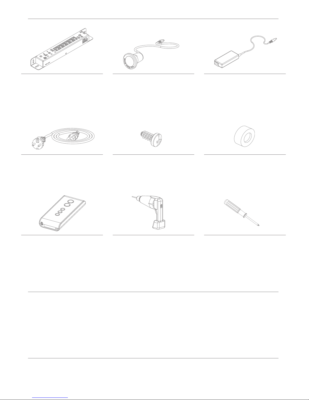
PART OVERVIEW / REQUIRED TOOLS
TECHNICAL SPECIFICATIONS ADAPTER
TECHNICAL SPECIFICATIONS RECEIVER
Product:
Art. code:
Dimensions:
Quantity:
Product:
Art. code:
Dimensions:
Quantity:
Product:
Art. code:
Dimensions:
Cable length:
Quantity:
Product:
Art. code:
Cable length:
Quantity:
Product:
Dimensions:
Product:
Art. code:
Cable length:
Quantity:
Product:
Art. code:
Dimensions:
Cable length:
Quantity:
Supply voltage:
Supply current:
Output:
Reception frequency:
Ambient temperature:
Product size:
Product weight:
Input:
Product size:
Product weight:
Temperature:
100-240 VAC
1.4A
24V
50/60Hz
-30 +60 ˚C
150x50x32mm
275 gram
24V
226x32x22mm
204 gram
5-40 ˚C
Product:
Art. code:
Dimensions:
Quantity:
Product:
Dimensions:
RECEIVER UNIT
50544
199x28x22mm
1x
RECEIVER EYE
22476
1450xø16mm
1x
AC-DC ADAPTER
70087
150x50x32mm
175cm
1x
SPACER
95227
25x10mm
1x
SCREWDRIVER
P1
POWER CABLE
70105
200cm
1x
REMOTE CONTROL
50498
80x35x15mm
175cm
1x
SCREW
95071
3.9x13mm
2x
DRILL
ø2.5
ø16
.3
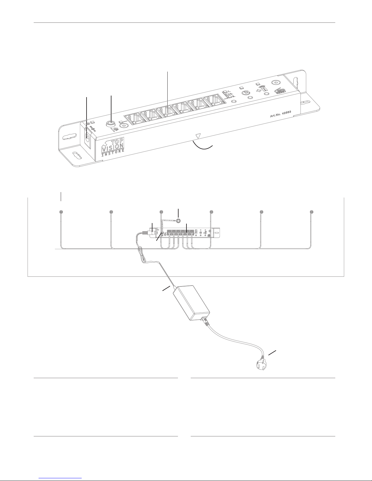
F
A
A
B
C
D
E
F
G
H
= RJ cables
= RJ ports
= External IR receiver eye port
= External IR receiver eye
= DC in port
= AC-DC adapter
= Power plug / outlet location
= Internal IR receiver eye
NOTE EXTERNAL RECEIVER EYE
You can either use receiver eye H,
where the eye will be directly behind
the receiver unit, or the external
receiver eye D, which allows you to
place the receiver eye up to 125cm
away from the receiver unit.
E
E
B
C
H
B
D
C
G
POSITIONING OF THE RECEIVER UNIT
Please note that the distance from A (RJ cables
of the eyewear display columns) to B (RJ ports)
does not exceed 125cm.
Please note that the distance from E (DC in port)
to F (AC-DC adapter) does not exceed 170cm.
Please note that the distance from C (IR
receiver eye port) to D (IR receiver eye) does not
exceed 125cm.
Please note that the distance from E (DC port)
to G (power outlet) does not exceed 350cm.
Even before deciding where you will mount your receiver unit, please keep the following lengths of the
various cables in mind.
A TO B
E TO F
C TO D
E TO G
.4

CHOSING INTERNAL OR EXTERNAL RECEIVER EYE
Before you mounting your receiver unit, decide if you want to use the internal or external receiver eye.
You can either use the internal receiver eye H, where the eye will be directly behind the receiver unit, or the
external receiver eye D, which allows you to place the receiver eye up to 125cm away from the receiver unit.
When using the external receiver eye D, you need to drill a hole of ø16 mm,
no further then 125cm from the receiver unit.
For drilling and mounting instructions, see page 7
When using the internal receiver eye H, you need to drill a hole of ø11,5 mm,
in the center of where you will mount the receiver unit.
For drilling and mounting instructions, see page 9
OPTION 1: USING AN EXTERNAL RECEIVER EYE
OPTION 2: USING AN INTERNAL RECEIVER EYE
.5

A A
A
B B
B
C C
D
D
D
D
C
Option 1
HORIZONTAL - STRAIGHT
Option 2
HORIZONTAL - FLAT
Option 3
VERTICAL - STRAIGHT
A
B
C
Option 4
VERTICAL - FLAT
Min. 40mm Min. 120mm
A A
Min. 1mm Min. 200mm
B B
Max. 1500mm from oor
Min. 45mm
Max. 1500mm from oor
Min. 90mm
C
D
C
D
Min. 90mm Min. 1mm
A A
Min. 200mm Min. 200mm
B B
Max. 1500mm from oor
Min. 45mm
Max. 1500mm from oor
Min. 90mm
C
D
C
D
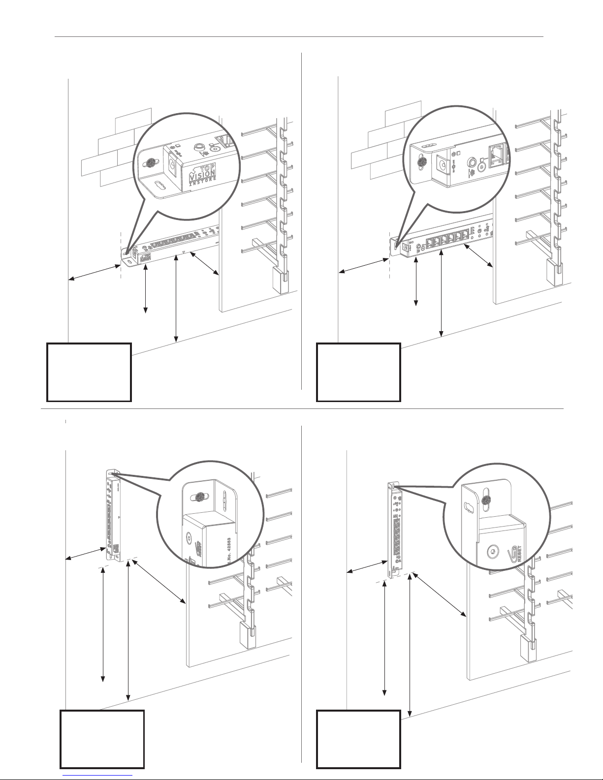
.6
OPTION 1: POSITIONING OF AN EXTERNAL RECEIVER EYE ON THE BACK OF A PANEL
A A
A
B B
B
C C
C
Option 1
HORIZONTAL - STRAIGHT
Option 2
HORIZONTAL - FLAT
Option 3
VERTICAL - STRAIGHT
A
B C
Option 4
VERTICAL - FLAT
Min. 40mm Min. 120mm
A A
Min. 1mm Min. 200mm
B B
Max. 1500mm from oor
Min. 45mm
Max. 1500mm from oor
Min. 90mm
C
D
C
D
Min. 40mm Min. 1mm
A A
Min. 200mm Min. 200mm
B B
Max. 1500mm from oor
Min. 45mm
Max. 1500mm from oor
Min. 90mm
C
D
C
D
DD
D
D
.7
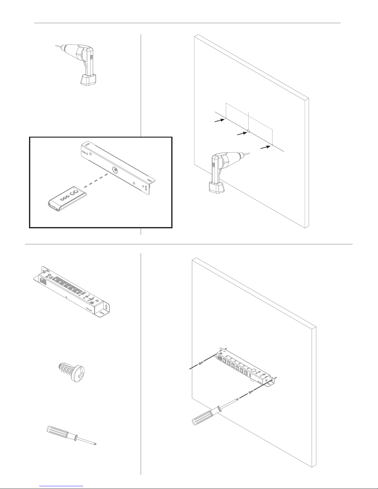
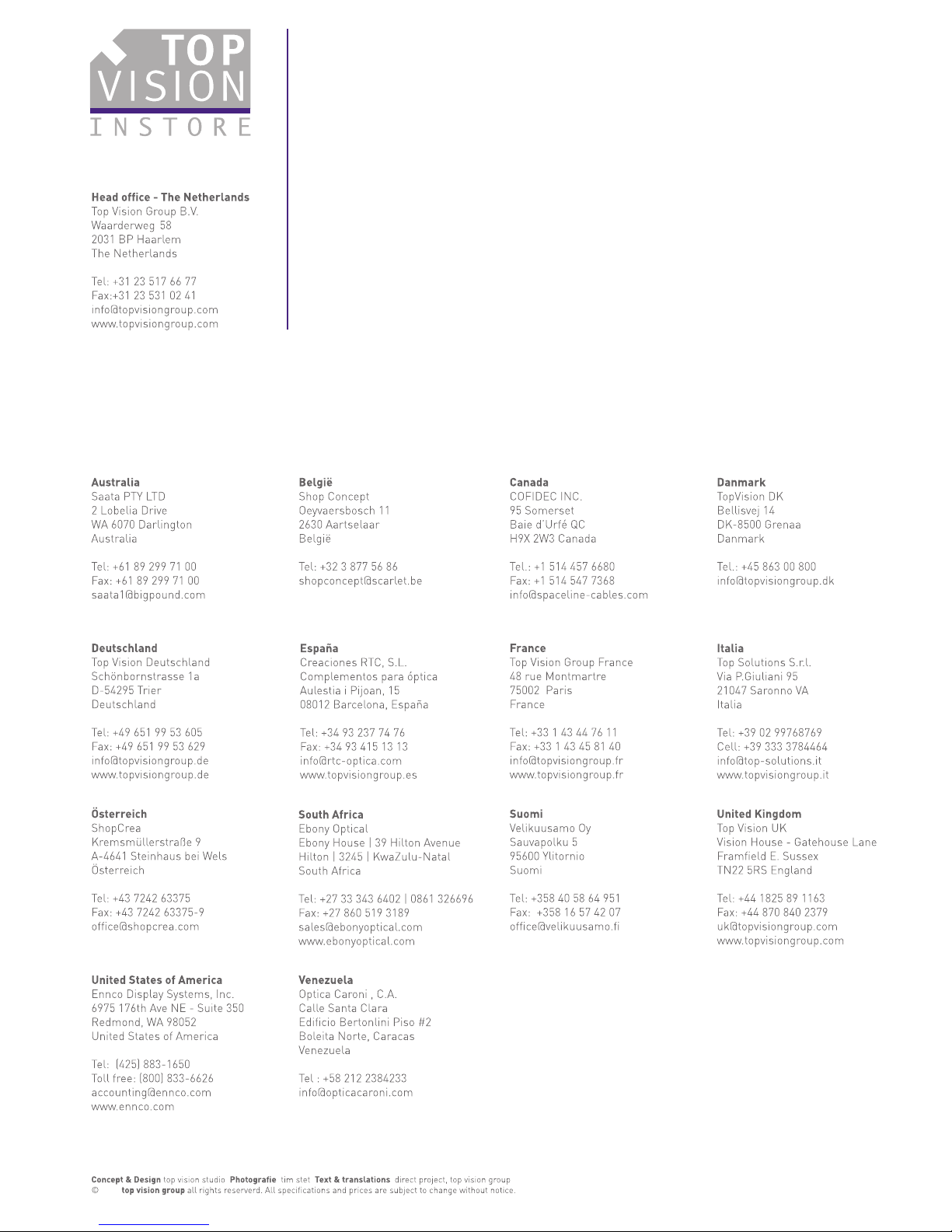
OPTION 1: POSITIONING OF AN EXTERNAL RECEIVER EYE ON THE BACK WALL

SCREW
95071
3.9x13mm
2x
SCREW
95071
3.9x13mm
2x
DRILL
ø2.5
182mm
2.5mm predrill
RECEIVER UNIT
50544
199x28x22mm
1x
SCREWDRIVER
P1
OPTION 1: MOUNTING THE RECEIVER UNIT WITH AN EXTERNAL RECEIVER EYE
1
2
Using option with external receiver eye
.8
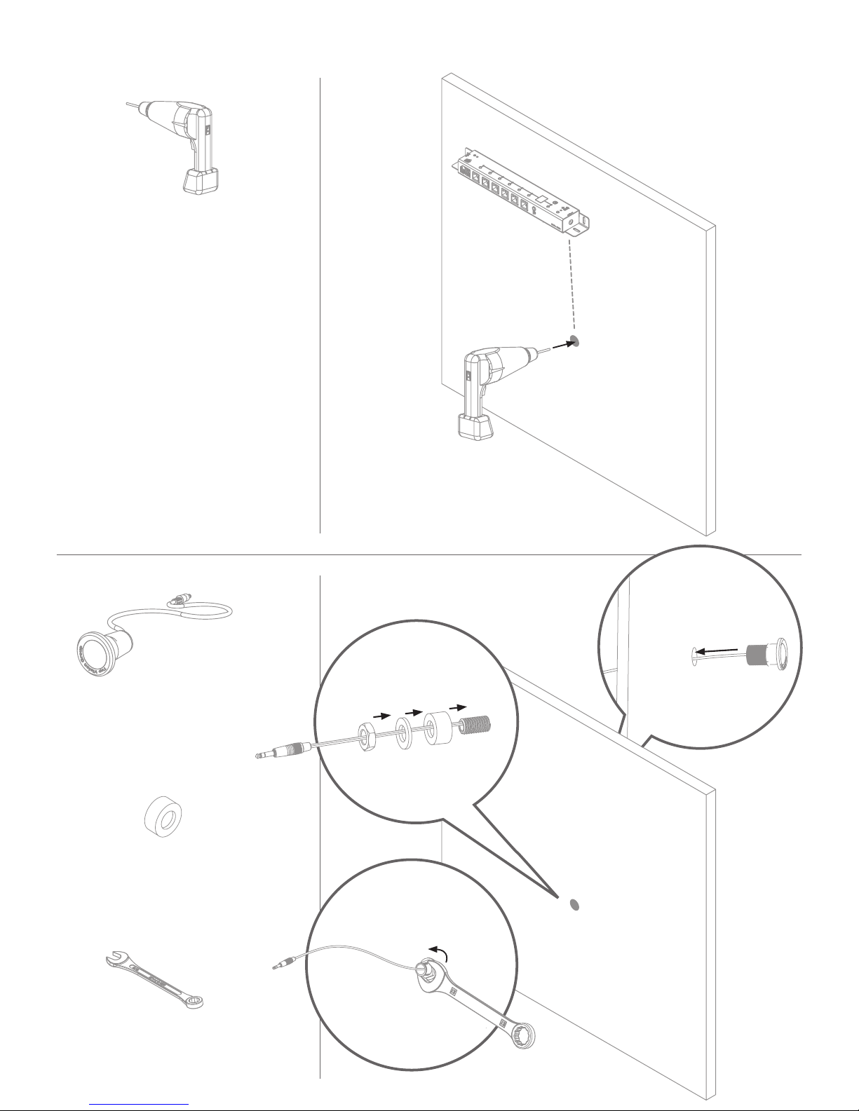
DRILL
ø16
RECEIVER EYE
22476
1450xø16mm
1x
16mm drill
#22
SPACER
95227
25x10mm
1x
3
4
Max. 125cm
.9

A
B
C
D
Option 1
HORIZONTAL - FLAT
Min. 120mm
A
Min. 200mm
B
Max. 1500mm from oor
Min. 90mm
C
D
MOUNTING A RECEIVER UNIT WITH AN INTERNAL RECEIVER EYE ON A BACK OF A PANEL
D
A
B
C
Option 2
VERTICAL - FLAT
Min. 1mm
A
Min. 200mm
B
Max. 1500mm from oor
Min. 90mm
C
D
.10
OPTION 2: POSITIONING OF AN INTERNAL RECEIVER EYE ON THE BACK OF A PANEL
SCREW
95071
3.9x13mm
2x
SCREW
95071
3.9x13mm
2x
PRE DRILL
ø2.5
DRILL
ø11.5
91mm 91mm
SCREWDRIVER
P1
1
2
Using option with internal receiver eye
A
B
A
B
A
.11
OPTION 2: MOUNTING THE RECEIVER UNIT WITH AN INTERNAL RECEIVER EYE
RECEIVER UNIT
50544
199x28x22mm
1x

12
3
ASSEMBLING THE CABLES
RJ CABLES TO COLUMNS
DC CABLE TO TRAFO
JACKPLUG TO IR RECEIVER EYE
GREEN LED “POWER ON”
.12

-
-
Note! This action has no effect on the timer settings.
Your display will now no longer react to any remote control.
Add a new IR code by following the steps in the previous paragraph.
-
-
-
-
-
Note! 2 low beeps will tell you that this IR code was already programmed.
-
-
Note! If this last step is forgotten, the system will automatically exit the
programming mode after 15 seconds, conrmed by 3 short beeps.
Press the Add RC button until you hear a beep.
The RC LED will start blinking.
As long as the RC LED blinks, you can add IR codes.
Aim your remote control at the receiver eye and press the button
of the remote control.
A short melody will conrm if the new IR code was accepted.
Again, press the Add RC button to exit the programming mode.
3 short beeps will conrm exiting.
Press the Reset button with a paperclip until you hear a beep.
All known IR codes are now deleted.
PROGRAMMING
ADDING REMOTE CONTROL IR CODES
A
B
C
REMOVING ALL REMOTE CONTROL IR CODES
Power LED
Reset button
RC LED
Timer LED
Interaction LED Grouping LEDs
Add RC button
Timer button
Grouping button
.13

Press the Grouping button.
Grouping LED #1 will lit up.
The receiver unit is now programmed as group #1.
Press the “Grouping button” again to switch to group #2 or #3
When the #3 LED is lit, and you press the “Grouping button” once more,
then the receiver will no longer be part of any group, and will only respond
to the “open/close” buttons of your remote control.
-
-
-
-
-
Note! pressing the “Reset button” has no effect on group settings.
You can only change the group settings by using the “Grouping buttons”.
-
-
-
-
-
-
-
-
-
-
Note! If this last step is forgotten, the system will automatically exit the
programming mode after 15 seconds, conrmed by 3 short beeps.
Note! The programmed timer interval only apply to the columns that are
connected to the receiver you just programmed.
Note! Pressing the Reset button has no effect on the timer settings.
You can set your receiver to a specic group (1 to 3), so it will only react to the corresponding 1-2-3 buttons of
your remote control. This way, you can make groups of your sets of columns that are connected to different
receivers, allowing you to open only a specic “brand” or “category” of frames.
CREATING GROUPS OF COLUMNS
By setting the timer interval, your eyewear display column will close automatically after a set time period
(1 to 9 minutes), indicated by 3 short beeps.
CHANGING THE TIMER INTERVAL FOR AUTOMATIC CLOSING
A
A
B
B
C
Press the Timer button.
The Timer LED will lit up.
The automatic closing function is now activated
In order to change the length of time before the system automatically closes,
press the Timer button for 3 seconds.
The Timer LED will start blinking.
The numbered Grouping LEDs will indicate the length of interval time.
LED 1 = automatic closure after 1 minute
LED 1+2 = automatic closure after 5 minutes
LED 1+2+3 = automatic closure after 10 minutes
Keep pressing the Grouping button until the interval reaches your desired length of time
To exit the programming mode press the Timer button again.
3 short beeps will conrm exiting.
The Timer LED will stop blinking.
.14

WARRANTY
.15
Your Top Vision product is warranted by Top Vision Group B.V. for a period of 24 months from the date
of purchase under the therms of our general conditions. The international Top Vision warranty covers
material and manufacturing defects.
The manufacturer’s warranty does not cover:
1. The battery of the remote control.
2. Damage resulting from improper handling or assembly.
3. Possible consequential damage resulting e.g. from defects, use, improper use or non functioning
of the display.
In case of defects covered by the warranty, your Top Vision product or the parts that are malfunctioning
will be replaced free of charge. The warranty for the replacement display or display-parts ends twenty four
months after the date of purchase of the replacement display or display-parts. Any further claims againts
Top Vision Group B.V. e.g. for compensation damage, withdrawal from the purchase contract or refund
of the purchase price are excluded. Your dealer carries sole responsibility for any other guarantees. The
warranty becomes void in the event of servicing or repair of the display by any person not duly authorized
by Top Vision Group B.V. or its representatives. In case of a defect, please contact your ofcial Top
Vision dealer or one of our authorized distributors as mentioned on www.topvisiongroup.com. The above
manufacturer’s warranty does not affect the purchaser’s right against the seller nor any other statutory
rights the purchases may have.
For Top Vision service agent addresses, see the backside of this manual or visit www.topvisiongroup.com.
Project Manual-RECEIVERPRO9
2017 Rev 30-05-2017
Table of contents


