Topband TB51100F-T110E User manual

Version: V02 Page 1 of 21
TB51100F-T110E Lithium battery
User Manual
Operation and maintenance manual
Version: V-00

Version: V02 Page 2 of 21
Description
This manual describes in detail the methods and steps for safe installation and operation of Topband
TB51100F-T110E series lithium battery pack. Please read the instructions carefully before installing the
product and during the entire installation process. If you have any questions on this manual, please do not
hesitate to contact Topband.
Tips
The information contained in this manual is accurate when it’s issued. Topband reserve right to change
specifications(such as optimization, upgrade or other operations) without prior notice. In addition, the figures in
this document are only used to help understand system configuration and installation instructions, which may be
different from the actual items at the installation.
Shenzhen Topband Battery Co., Ltd
Address: Topband Industrial Park, Liyuan Industrial Zone, Shiyan, Bao'an, Shenzhen, China
Postcode: 518108
Tel: +86-755 2765 1888
Fax: +86-755 8178 5047
Web: www.topband.com.cn / www.topbandbattery.com
Legal Terms
Topband will retain the copyright of this document, do not extract, copy or translate in any ways without the written permission.

Version: V02 Page 3 of 21
Disclaimer
Please read this manual and specs carefully before the installation, operation or maintenance, be familiar with
this equipment and follow the local safety regulations and related operating procedures. At the same time, only
qualified professionals are allowed to install, operate and maintain the system, otherwise it may cause product
damage or personal safety risks. The precautions mentioned in this manual are under normal condition, If there’s
any special use environment, please contact Topband for confirmation.
Any actions (such as use, intentional damages, etc.) against the general safety operation, or do not follow this
manual and technical specifications, the users will no long to have the warranty and qualification of this product.
Meanwhile, the manufacturer will be not responsible for the product damage, personal injury.
Changes
Version
Issued date
Revised records
Issued by
V00
Pop

Version: V02 Page 4 of 21
Content
1. Safety Warning........................................................................................................................................................5
1.1 Safety precautions .........................................................................................................................................5
1.2 Wearable device ............................................................................................................................................6
1.3 Other tips.......................................................................................................................................................6
1.4 Emergency safety measures...........................................................................................................................6
2. Product Overview....................................................................................................................................................7
2.1 Background overview ....................................................................................................................................7
2.2 Product features ............................................................................................................................................7
2.3 Princible .........................................................................................................................................................7
3. Product Description ................................................................................................................................................8
3.1 Basic parameters............................................................................................................................................8
3.2 Interface definition ........................................................................................................................................8
3.3 Performance specification ...........................................................................................................................12
3.4 Protection ....................................................................................................................................................13
4. Installation and Usage...........................................................................................................................................14
4.1 Installation preparation ...............................................................................................................................14
4.1.1 Safety regulations .............................................................................................................................14
4.1.2 Environmental requirement..............................................................................................................14
4.1.3 Installation tools ...............................................................................................................................15
4.1.4 Safety tips..........................................................................................................................................15
4.2 Unpack .........................................................................................................................................................15
4.2.1 Unpack precautions ..........................................................................................................................15
4.2.2 Check and confirm ............................................................................................................................15
4.3 Installation ...................................................................................................................................................16
4.3.1 Installation check ..............................................................................................................................16
4.3.2 Installation procedures .....................................................................................................................16
5. Maintenance and Abnormality Handling ...........................................................................................................20
5.1 System activation and dormancy.................................................................................................................20
5.1.1 System activation..............................................................................................................................20
5.1.2 System dormancy..............................................................................................................................20
5.2 Regular maintenance...................................................................................................................................20
5.3 Alarm or abnormality handling....................................................................................................................21
6. Transport, Storage.................................................................................................................................................22

Version: V02 Page 5 of 21
1. Safety Warning
1.1 Safety precautions
警告
如不遵守本节所述的注意事项,可能会对人员造成严重伤害或财产损失。
!
Explosion risk
—Do not impact the battery with heavy objects.
—Do not squeeze or pierce the battery pack.
—Do not throw the battery pack into the fire.
Fire risk
—Do not expose the battery pack to the condition over 100°C.
—Do not put the battery near a heat source, such as a fireplace.
—Do not expose the battery pack to direct sunlight for a long time.
—Do not allow the positive and negative connectors of the battery to connect the conductive objects at the same
time.
Electric shock risk
—Do not allow non-technical personnel to disassemble the battery pack.
—Do not touch the battery pack with wet hands.
—Do not expose the battery pack to moisture or liquid environment.
—Do not mix batteries from different manufacturers or different kinds, types or brands.
Damage risk
—Do not allow the battery to contact with liquid,
short-circuit or reverse the positive and negative terminals of the battery.
—Do not use chargers or charging devices unapproved by the manufacturer to charge the battery.
—Do keep clear on top of the battery pack.
If fail to follow the precautions described may cause serious personnel injury or property damage.
Warning

Version: V02 Page 6 of 21
1.2 Wearable device
It is strongly recommended to wear the following safety equipment when installing and handling the battery pack.
Insulated gloves Safety Glasses Safety Shoes
1.3 Other Tips
•All the product are strictly inspected before shipment, please contact us for replacement if you notice there’s
any defectives such as swelling.
•Do not disassemble batteries and components; otherwise the manufacturer will not be responsible for any
damage caused by unauthorized disassembly or repair.
•Do enable the battery to be safely grounded before use to make sure the system in safe and normal
operation.
•Please ensure that the electric parameters of these devices are compatible mutually before connecting the
battery to other devices.
•Please take the environmental factors into careful considerations to ensure that the system can work in a
suitable condition as the environment and storage methods have a certain impact on the service life and
reliability of this product.
1.4 Emergency safety measures
Water invasion: Please cut off the AC power supply of the system first and then disconnect all switched under the
premise of ensuring safety.
Electrolyte or gas leakage: Please avoid contacting with the liquid or gas leakage if the electrolyte of battery pack
leaks. While if you have been exposed to leakages, please take these steps immediately:
Gas Inhalation: Evacuate the people in the contaminated area and seek medical aid as soon as possible.
Eye Contact: Flush your eye with clean and flowing water for 15 min, and seek medical aid as soon as possible.
Skin Contact: Thoroughly rinse the exposed area with soap and water to be sure no chemical or soap is left on
them, and seek medical aid as soon as possible.
Swallowing: Try to induce vomiting, seeks medical aid as soon as possible immediately.
Fire: Please use carbon dioxide fire extinguisher rather than liquid to put out fires.

Version: V02 Page 7 of 21
2. Product Overview
2.1 Background
The lithium-ion battery TB51100F-T110E adopts advanced LiFePO4 technology so the battery module has multiple
advantages of long cycle life, compact structure, light weight, stable performance, which is widely used in the
various environment. The system is integrated with smart battery management system and monitor module to
meet the unattended requirements, which is very suitable for the field of backup power supply, such as PV energy
storage, Micro base station, UPS, etc.
2.2 Product features
•Adopt high performance LFP cells with long lifespan, high safety and wide temperature range.
•With high energy density, compact structure, light weight, and no pollution.
•Built-in BMS with the management functions to battery voltage, current, temperature and battery health.
•With LED display for SOC and operating status, which is easy to read battery status.
•With Communication interface, there’re RS485 and CAN by default.
•Use smart balancing module to ensure the consistency of battery and to extend the service life.
•With intelligent design to conform to the national standard requirements, and support for remote
measurement, remote communication, remote control, remote adjustment.
•With optional heating function to be used in extremely low temperature area.
•With long lifespan of floating charge, stable performance and maintenance-free.
•With ultra-low consumption of BMS, self-discharge rate and capacity loss rate.
•Equipped with BMS secondary protection function and ultra-high system reliability
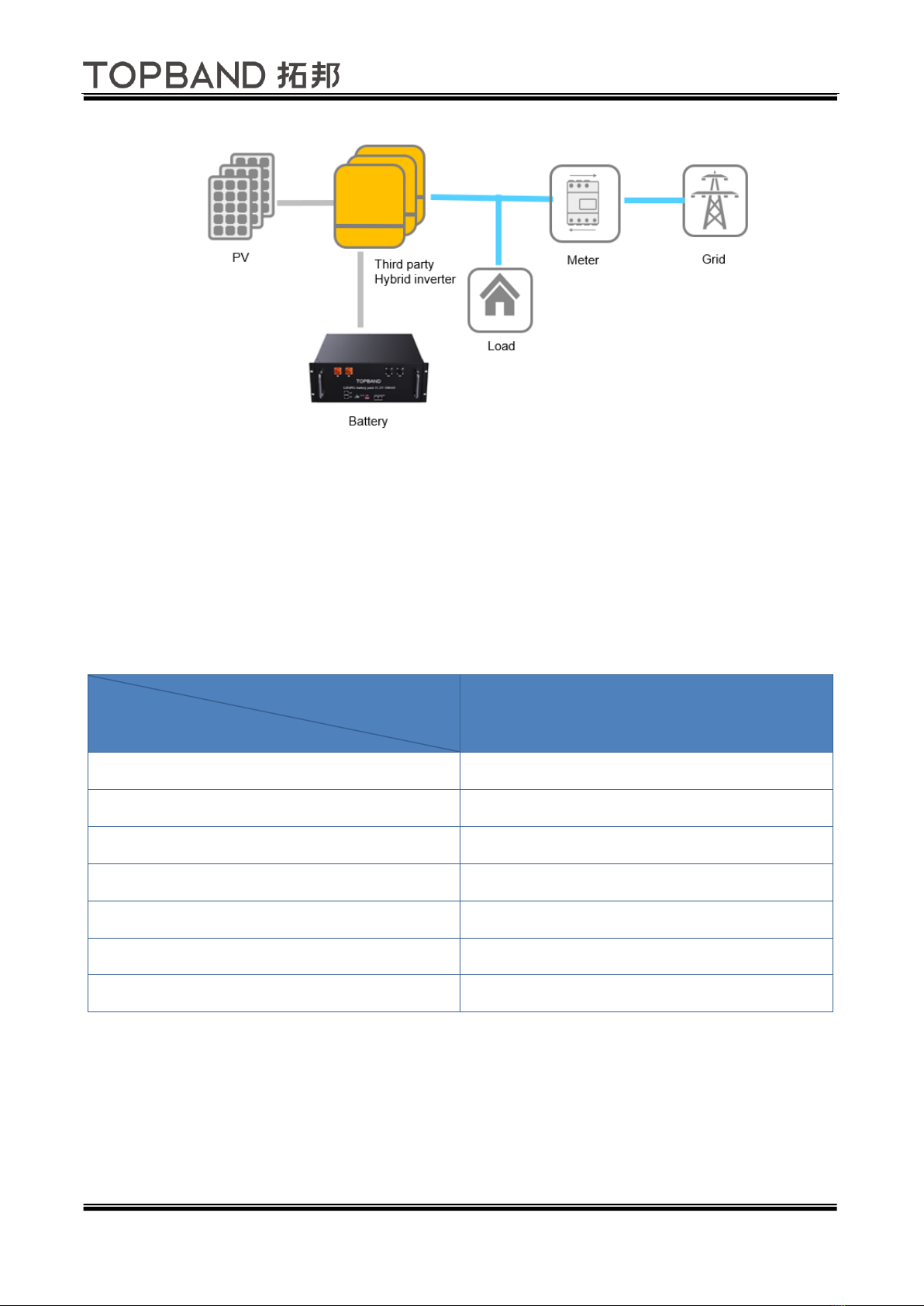
2.3 Principle
After starting the system, when the inverter works at on-grid mode, the photovoltaic solar energy will give priority
to supply the load if the photovoltaic is sufficient; if there is any surplus, it can be used to charge the battery first;
and for more surplus, it will be fed back to the grid. If the photovoltaic solar energy is insufficient or at night, it
will automatically switch to the battery to deliver electric power to the load and when it run out of energy also,
the excess power will be supplied by the grid.
When the inverter works at off-grid mode, both the load and battery are charged by photovoltaic solar energy
during the day, and the load will be supplied by the battery at night. Below is the overall framework of the system:
Version: V02 Page 8 of 21
3. Product description
3.1 Basic parameters
See the basic parameter of TB51100F-T110E lithium battery as table 3-1:
Table 3-1 Specification
Model
Parameter
Nominal Voltage (V)
51.2
Nominal Capacity (Ah)
100.0
Energy (KWh)
5.12
Width (mm)
442.0±2
Height (mm)
177.5±2
Depth (mm)
450±2
Weight (kg)
~47kg
3.2 Interface definition
See the interface description of TB51100F-T110E series lithium battery as table 3-2, please note the position of
the corresponding interface varies from model to model but with same definition is same.

Version: V02 Page 9 of 21
Table 3-2 interface description
No.
Items
Usage description
Remark
A
Mounting ear
Used to fix with the rack or cabinet
B
GND
Grounding point
C
Handles
For the handling, installation and
disasembly of battery
D
Positive terminal
Used to connect the charger or the
positive of the load device
2Pin
E
CAN communication
For the connection of internal CAN
communication
See Table3-3
F
LED indicator *4
Used to indicate the remaining
capacity of the battery
See Table 3-6
G
ALM
Used to indicate the battery
abnormality
See Table 3-6
H
RUN
Used to indicate the operating status
of the battery
See Table 3-6
I
Dial switch address
Used to set the address bit of battery
module when multiple batteries are
connected in parallel.
See Table 3-5
J
RS 485 communication
Used to connect with inverter or
upper computer
See Table 3-3
K
Reset
For manual switch, reset or other
operations in the system
See Table3-4
L
Negative terminal
Used to connect the charger or the
negative of the load device
2Pin

Version: V02 Page 10 of 21
Table 3-3 Communication PIN description
PIN No.
RS485
CAN
1
RS485_A
CAN_L
2
RS485_B
CAN_H
3
NC
SGND
4
NC
NC
5
NC
NC
6
NC
SGND
7
RS485_B
CAN_H
8
RS485_A
CAN_L
Table 3-4 Button description
Activate
When the BMS is in dormancy mode, press and hold the button for 2s and release it. It will
back to normal situation after the LED indicators light up in turn.
Dormancy
When the BMS is in active state, press and hold the button for 3s and release it. It will back
to normal situation after the LED indicators light up in turn.
Reset
When the BMS is in standby or working mode, press and hold the button for 6s and release
it, and the BMS will be reset, the system restart.
Table 3-5 Dial switch address
No.
Dial switch address
RS485
CAN
#1
#2
#3
#4
#5
#6
0
OFF
OFF
OFF
OFF
See table 3-5-2
Pack 0
Invalid
1
ON
OFF
OFF
OFF
Pack 1
Master
2
OFF
ON
OFF
OFF
Pack 2
Slave
3
ON
ON
OFF
OFF
Pack 3
Slave
4
OFF
OFF
ON
OFF
Pack 4
Slave
5
ON
OFF
ON
OFF
Pack 5
Slave
6
OFF
ON
ON
OFF
Pack 6
Slave
7
ON
ON
ON
OFF
Pack 7
Slave
8
OFF
OFF
OFF
ON
Pack 8
Slave
9
ON
OFF
OFF
ON
Pack 9
Slave
Note: The BMS of master pack does not support to connect the inverter and the host computer at the same time,
otherwise it will occur the communication errors.
Table 3-5-2 CAN /RS485 Communication
Baud rate/ Compatible inverter
#5
#6
250Kbps/ Victron
0
0

Version: V02 Page 11 of 21
500Kbps/ Victron
1
0
500Kbps/
Goodwe/Sungrow/Solis/Deye
0
1
500Kbps/ SMA/STUDER/Sofar
1
1
Table 3-6 LED indicator description
Mode
Normal/Alar
m/Protection
RUN
ALM
LED indicator
description
●
●
●
●
●
●
Shutdown
Dormancy
OFF
OFF
OFF
OFF
OFF
OFF
ALL OFF
Standby
Normal
FLASH1
OFF
According to battery state of charge
Standby
Warning
FLASH1
FLASH3
Low voltage
Charge
Normal
ON
OFF
According to battery state of
charge(highest SOC LED: FLASH2)
All alarm except
the over charge
Warning
ON
FLASH3
Over-current
OFF
ON
OFF
OFF
OFF
OFF
Stop charging
Discharge
Normal
FLASH3
OFF
According to battery state of charge
Warning
FLASH3
FLASH3
Under voltage
OFF
FLASH3
OFF
OFF
OFF
OFF
Stop charging
Over current,
short circuit
OFF
ON
OFF
OFF
OFF
OFF
Stop charging
Temperatu
re
Protection
OFF
ON
OFF
OFF
OFF
OFF
Stop
charging/dischar
ging
Failure
Cell failure
NTC failure
Sensor failure
MOS failure
Charger HV
failure
OFF
ON
OFF
OFF
OFF
OFF
Stop
charging/dischar
ging
Status
Charge
Discharge
Capacity indicator
L4●
L3●
L2●
L1●
L4●
L3●
L2●
L1●
SOC (%)
0~25%
OFF
OFF
OFF
FLAS
H2
OFF
OFF
OFF
ON
25~50%
OFF
OFF
FLASH2
ON
OFF
OFF
ON
ON
50~75%
OFF
FLAS
H2
ON
ON
OFF
ON
ON
ON
75~100%
FLASH2
ON
ON
ON
ON
ON
ON
ON
Running indicator●
ON
FLASH (FLASH3)

Version: V02 Page 12 of 21
3.3 Performance Specification
Items
TB51100F-T110E
Rated voltage
51.2V
Voltage range
40.0~57.6V, Shipping voltage>51.2V
Charge voltage
56.0V
Float charge voltage
54.6V
Inverter/Load Cut-off
49.0V
Low Voltage Disconnect
48.0V
Nominal energy
5.12KWh
Nominal capacity
100Ah
Standard charge current
≤50A
Max. charge current
50A
Standard discharge
current
≤50A
Max. discharge current
Auto adjust when communicating
100A( No communication, ≤35℃)
Peak discharge current
<120A@15s
Communication
RS485 /CAN
Operation temperature 1
Charge: 0~45℃Discharge:-10~55℃
Storage temperature
0℃<T<30℃
<6 months
-10℃<T<45℃
<3 months
Recommended environment
15~35℃, 5~75%RH
注意
当环境温度超出操作范围,电池组停止操作来保护自己。电池的最佳操作温度范围15°C到35°C。频繁暴露在严酷的
气温会恶化电池组的性能和循环寿命。
!
The battery pack will stop working when the ambient temperature exceeds the operating range, so the recommended working
temperature range is 15℃to 35℃. Frequently used in the severe environment will deteriorate its performance and cycle life.
Attention

Version: V02 Page 13 of 21
3.4 Protection
Items
Description
Remark
Cell/PACK high-voltage
When charging, the system will stop charging if any cell or
PACK voltage reach the protection value and it will be
released only when both Pack and cell voltage back to the
release voltage range.
Automatic recovery
Cell/PACK low-voltage
When discharging, it will reach over-discharged
protection of battery to stop discharging if any cell or
PACK voltage is under the protection value and it will be
released only when all the cell voltage back to the release
voltage range.
Can Automatic
recovery. Please
charge timely,
otherwise it may
be in Low-power
mode to be
over-discharged.
High temperature
When the battery cell, MOS, and ambient temperature
are higher than the set value, the system will stop
charging or discharging according to the category, or
disconnect at the same time.
Automatic recovery
Low temperature
When the battery cell, MOS, and ambient temperature
are higher than the set value, the system will stop
charging or discharging according to the category, or
disconnect at the same time.
Automatic recovery
Charge overcurrent
When the charging current is higher than the protection
value, the system will stop charging. And it will release
from the protection when the system delays after rated
time. Please note the maximum charging current
provided by power supply should not exceed the
protection value when using the battery.
Automatic
recovery. If locked
after three
consecutive times,
manual
intervention is
required.
Overload
When the discharging current is higher than the
protection value, the system will stop discharging. And it
will release from the protection when the system delays
after rated time. Please note the maximum discharging
current requested by the load should not exceed the
protection value when using the battery.
Automatic
recovery. If locked
after three
consecutive times,
manual
intervention is
required.
Short-circuit/Reversed
Polarity
Do not short-circuit
Release from
protection when

Version: V02 Page 14 of 21
removing the load
or charging the
battery
Temperature, Voltage,
Current Abnormal
Enter the failure mode, switch off the circuit breaker, no
charging and discharging.
Manual
intervention
dormancy mode
After reaching a certain condition, it will be in the
dormancy mode
Recoverable
4 Installation and Usage
4.1 Installation preparation
4.1.1 Safety regulations
Only qualified professionals are allowed to carry out the installation, operation and maintenance of
TB51100F-T110E series lithium batteries. Please read this manual and specs carefully before the installation, be
familiar with this equipment. During the installation process, please strictly follow the local safety regulations and
related operating procedures, and pay attention to the following points:
1. Confirm the inverter is produced by formal manufacturer and compatible with the lithium battery, and
check whether the parameters meet the requirements of section 3.3.
2. Please ensure all devices are shut-down before installation, and follow the manufacturer's specifications
and warnings.
3. Confirm the cable specs meet the requirements with neat wiring layout to avoid being exposed of these
cables when operating the power equipment.
4. Ensure the battery and the power system are reliably grounded during installation.
4.1.2 Environment requirement
The operating environment shall meet the following requirements:
Category
Description
Working temperature
-10℃-55℃
15℃-35℃(optimal temperature)
Relative humidity
5%~90%, No condensation
Altitude
<3000m
On-site requirement
Keep away from heat, direct sunlight;
No corrosive, explosive, or flammable gas;
No conductive dust that will damage the insulation;
Completely isolated from water, and no flammable or explosive
materials nearby.

Version: V02 Page 15 of 21
4.1.3 Installation Tools
Installation Tools & details
Screwdriver (slot, cross)
Multi-meter
Wrench
Clamp meters
Diagonal pliers
Insulating tape
Needle nose pliers
Thermometer (observe the installation
environment)
Clamping pliers
Anti-static bracelet
Wire stripper
cable ties
4.1.4 Safety Tips
Please equip with a self-contained breathing apparatus and carbon dioxide fire extinguisher that meets
regional/international standards in the vicinity of where the lithium battery placed to make sure the safety.
4.2 Unpack
4.2.1 Unpack precautions
-Please load and unload it in accordance with the specified requirements to prevent sun and rain when you
receive the equipment.
-Please check and confirm the goods (such as quantity, package appearance, etc.) according to the "delivery list"
before unpacking.
-Do light take and put during unpacking process to protect the surface coating of the object;
-Please record and feedback to the manufacturer if the inner packing is damaged after unpacking.
4.2.2 Packing list
One carton contains the items listed below, please check carefully after unpacking.
Battery Communication (Optional) Paper/E-User Guide Factory report & List

Version: V02 Page 16 of 21
4.3 Installation
4.3.1 Installation check
Please check again by on-site personnel on the following conditions or equipment whether meet the
requirements before installation:
• Check if there’s enough space for installation, and if the load-bearing capacity of the bracket or cabinet meets
the weight requirements
• Check whether the power cable used meets the maximum current requirement for operation;
•Check whether the overall layout of power supply equipment and batteries at the construction site is
reasonable;
• Check whether the installer is wearing anti-static wristband
• Check whether there’re two people on the construction site for installation work
• Check if there’s potential risks at location of installation site, e.g. flooding, sun exposure, corrosion, and salt
spray
4.3.2 Installation procedures
4.3.2.1 Get the battery ready
1.Get the battery ready, ensure all the battery indicator is in OFF, and confirm whether the appearance of the
battery is normal;
2.Confirm both the battery breaker and the system breaker that connected the battery with inverter are
disconnected.
3. Turn on the signal switch of the battery, observe whether there is alarms on the panel, measure it with
multi-meter and record battery voltage, then check if it meets the parallel standard: open circuit voltage
difference < 0.5V;
4. After confirming that everything is OK, turn off the battery and put it at the installation preparation area for
ready-to-install:
Placement description:

Version: V02 Page 17 of 21
4.3.2.2 Structure and electrical installation
1. Get the cabinet ready and assemble it as integrator requested to ensure the cabinet is installed horizontally and
reasonable location layout;
2. Prepare all the battery packs, place the batteries on the cabinet tray via manual-lifter, and push the batteries
into the cabinet, then fix the battery mounting ears to the cabinet through the crown-nuts;
3. Please double check the battery is in shut down and disconnect the circuit breaker, unscrew the
positive/negative terminal bolts of the battery pack, then connect the batteries to the positive/negative bus bar
through cables;
4. Unscrew the grounding screw, connect the battery and the grounding bus bar of cabinet through the
yellow-green flexible wire to ensure that all connections are reliable
5. Connect the CAN communication interface between the batteries, set the dial switch address as Table 3-5, and
insert the matching resistance terminal into the CAN port at the end of battery, as Figure 4-4

Version: V02 Page 18 of 21
6. Connect the RS485 port of the master battery module to the battery communication interface of the inverter,
meanwhile, connect the bus bar of the battery cabinet and the battery input of the inverter through the system
breaker;
7. Starting from the master, turn on all battery modules by pressing the reset button, close the battery breakers
one by one, and observe whether the breakers can’t be closed and any overcurrent occurs during the process. If
all works normally, go to the next step; If there’s battery breaker can’t be closed or overcurrent occurs, please
measure the battery voltage separately to evaluate whether it’s caused by a large voltage difference.
4.3.2.3 Enabling system
After completing above all steps, turn on the system breaker between the battery cabinet and the inverter, run
the inverter and open the setting menu, then select 'Lib’ in the battery type, and press the battery on switch to
measure the battery voltage , If normal output then turn on the battery to access breaker. At the same time, check
whether the communication is normal, if all is ready then enable the system.
Table 4-1 Inverter setting parameters
No.
Items
Description

Version: V02 Page 19 of 21
1
Average charge voltage
56.0V
2
Float charge voltage
54.6V
3
Low SOC limit
10%
4
Inverter/Load Cut-off
49.0V
5
Charging current limited value
50A*N (N is the Quantity of the battery pack)
4.3.2.4 Working at High/Low temperature
Do not charge the battery when it is used below 0℃, while if you want to make it, you need to add internal
heating device to heat the battery temperature to ≥0℃and then charge the battery. The charge factor of
batteries in high and low temperature environments should follow the below recommendations:
Operations
Temperature range
Recommend current
Charge
0~10℃
<0.1C(force)
10~20℃
<0.3C
20~35℃
<0.5C
35~45℃
<0.2C
Discharge
-10~55℃
<0.5C

Version: V02 Page 20 of 21
5. Maintenance and Abnormality handling
5.1 Activation and dormancy
5.1.1 System activation
If it meets any of the following conditions when the system is in low-power mode, the system will exit from it and
enter the normal running mode:
When the charger is connected, the output voltage of the charger need to higher than 48V.
1) Turn on the power button.
2) In the case of battery in sleep mode(except battery over-discharge, battery damage, etc.), the monitoring
software can wake up the battery.
Remark: The battery will be in low-power mode after cell or PACK reach over-discharged protection, wake up
every 4 hours to turn on the charge and discharge MOS. If it can be charged, it will exit from dormancy mode for
charging normally; if it can’t be charged after 10 consecutive automatic wakeups, it will no longer wake up
automatically
When the system is defined as charging ends, the recovery voltage still not reach after 2 days of standby (stand-by
time set value), then it will be forced to re-charging till the end of charging again.
5.1.2 System Dormancy
When any following conditions occurs, the system will be in Low Power mode:
1) The over-discharge protection of the cell or PACK is not released within 60 seconds
2) The lowest cell voltage is lower than the dormancy voltage, and the duration up to the dormancy delay time
(meanwhile, it meets the requirements of no communication, no protection, no balance, and no current).
3) Shut down through the upper computer.
4) Make sure that the input terminal disconnect to external voltage before entering dormancy mode, otherwise it
will fail to access to Low Power mode.
5.2 Regular maintenance
1) Regularly check whether the usage environment meets the requirements, and ensure the installation location is
far away from heat sources.
2) Check whether the charging and discharging of the battery pack are normal. You need to recharge in time for
Table of contents


