manuals.online logo
Brands
  1. Home
  2. •
  3. Brands
  4. •
  5. Topgreener
  6. •
  7. Wireless Router
  8. •
  9. Topgreener WFSM Wiring diagram

Topgreener WFSM Wiring diagram


WFSM
WIFI Single Relay Smart Switch Module


SPECIFICATIONS
Voltage.......................................................................120-277VAC, 50/60Hz
Maximum Load requirement....................................................................10A

FEATURES 
z
z
z
z


DESCRIPTION 
INSTALLATION
Simple Wiring Diagram: Fig1
3-way Circuits
Wiring Diagram: Fig2
IMPORTANT NOTE ABOUT 3-WAY CIRCUITS
The term “3-way circuit” refers to a circuit with two switches and one load (light)
like you find at the top and bottom of a stairway. There are many ways
to physically wire a 3-way circuit and it is important to understand how the
circuit you wish to upgrade to WIFI device is wired. One of the ways, the of
WFSM to wire a 3-way switch 2(Fig2), then wire to 3-way switch, and then
wire to the Neutral. Although very common and by no means a standard, it is
the easiest to convert to WIFI device. with this type of circuit, WFSM is seting
behind the switch 2. Do not change the wiring of switch1. Please note that
both switch 1 and switch 2 must be 3-way switch.
Please consult an electrician if you have trouble indentifying the type of wiring
circuit you wish to convert or if you do not feel confident in your ability to convert
the circuit to WIFI device.
1. WARNING : To avoid fire, shock, or death. Turn off power at circuit breaker or
fuse and test that power is off before wiring.
2. Remove wall plate and switch mounting screws.
3. Carefully remove the switch from the switch box.
4. Disconnect the wiring from the existing switch.
5. Connect the WFSM module as shown in the wiring diagram
6. Check connections to be sure they are tight and no bare conductors are exposed.
7. Insert the WFSM module into the box first, then wire the existing switch.
8. Attach the wall plate.
9. Restore power at the circuit breaker and test the system.


INSTALLATION INSTRUCTIONS
Protocol.....................................................................................IEEE 802.11b/g/n
System Requirements...............................Android 4.1 or higher, iOS 8 or higher
Indoor Use Operating Temperature................................32°F~104°F(0°C~40°C)
Type 1.B action, operating control
Wireless Type......................................................................................... 2.4GHz
You can control lights, fans, humidifiers, Air conditioner, and any small appliances
in accordance with the Smart Switch Module’s specifications.
You can Turns your devices on or off at any time or any where have Internet
using the free Tuya Smart App on your smartphone.
Compatible with the Amazon Echo, the free Tuya app compatible with any
Android (4.1 and higher) or iOS (iOS 8 and higher) smartphone.
You can efficiently conserve energy and save money while using this Smart
Switch Module.
controlled by manual or you can through App to remote control turn on/off light,
The WFSM Plug is our industry's first WIFI Single Relay Smart Switch Module,
which can make our life more convenient. This Smart Switch Module can be
countdown and make weekly plan after connect 2.4GHz WIFI .
-01- -02- -03-
Load
OPERATIONS
Power/ Program Button
Manual Control
The Power/ Program Button or connected switch on the WFSM smart switch
1. Manually turn ON the Module: press and release the program button or toggle
the connected switch. The Blue LED indicator will turn ON, and the appliance
2. Manually turn OFF the Module: press and release the program button toggle
the connected switch. The Blue LED indicator will turn ON, and the appliance
Tuya Smart App Control
1. Download Tuya Smart app from the App Store or Google Play.
2. Connect mobile device to your 2.4GHz WIFI network. Please note this
Smart outlet can only be connected to 2.4GHz network.
3. Launch Tuya and follow the in-app instructions to connect the WIFI outlet
to your network.
a. Login the Tuya b. Click the d. Select the
"Electrical outlet"
" Add Device" c. Click the
" All device"
Hot
Neutral
Aux
Neutral
(White)
Hot
(Black)
Neutral
(White)
Neutral
(White)
~100-240V, 50/60Hz
Switch 1 Switch 2
Load
Hot
Neutral
Aux
Neutral
(White)
Hot
(Black)
Neutral
(White)
Neutral
(White)
~100-240V, 50/60Hz
Switch Connected Switch Control
Toggle the connected switch to turn on and off three times and repeat the operation
two times after waiting above 10 seconds. When the load lamp turn on and off
module allows the user to:
will turn ON.
will turn OFF.
twice and then turn off that means you can connect the WIFI .
Oct, 2019
INSTALLATION INSTRUCTIONS
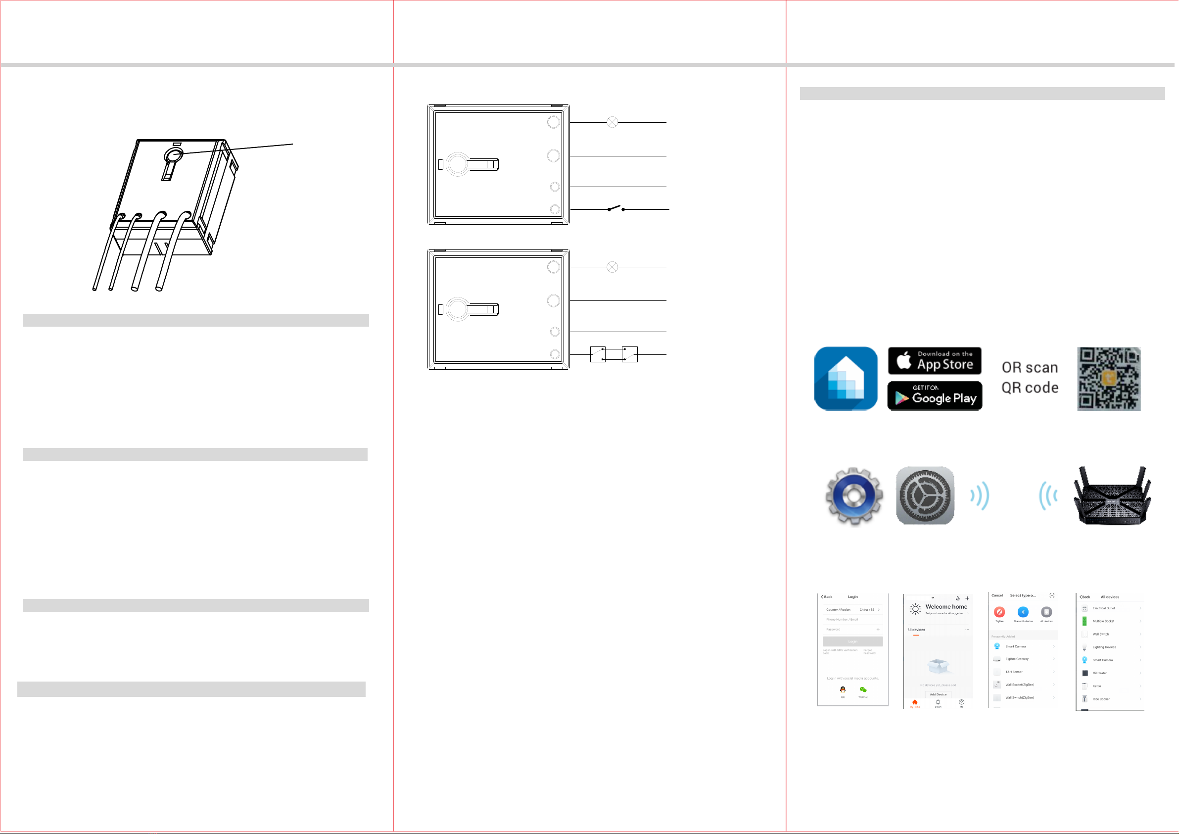
4. When the device is finished add, this WIFI Outlet can be opened, closed,
countdown ,making weekly plan and can check the electric quantity.
-04- -05- -06-
1. In the process of adding device, you must correctly select the router's WIFI
Please Note:
device name and fill in the correct WIFI password, otherwise the device will
not be able to add successfully.
2. This WIFI Outlet can only be paired with one phone device. If you want
multiple phones to control the WIFI Outlet, click the "profile" then chose
the " Device Sharing".
3. When the device fail to add in the App, please try to enter the AP mode. When
power is reconnected after the interruption, press and hold the program button
5 seconds until the LED indicator in quick blinks. Or connect the toggle switch, turn
When power is reconnected after the interruption, press and hold the program button
on/off 3 times in 3 seconds then after 10 seconds turn on/off twice, the LED indicator
OPERATION AND LED INDICATION
Connecting to the network.
Quick Blinking Green:
Green bright after 2 seconds off: Connected to the network.
Solid Blue:
Off Blue: The WIFI Smart Switch is switched on.
The WIFI Smart Switch is switched off.
Soild Green: Network normaly or in standby mode.
AP mode.
Slow Blinking Green:
d. Click the
bottom button e. Enter your f. Finished
wifi password
on/off 3 times in 3 seconds then after 10 seconds turn on/off twice, the LED indicator
in quick blinks after that repeat the above operation again then the LED indicator
in slowly blinks that means successfully enter in AP mode.
5 seconds until the LED indicator in quick blinks. Or connect the toggle switch, turn
in quick blinks.
please note that: turn off-on-off-on-off that is connecting to the network .
Turn off-on-off-on that is entering AP mode.
Restoring Factory Defaults
Press and hold the program button 5 seconds until the LED indicator in quick blinks.
Or connect the toggle switch, turn on/off 3 times in 3 seconds then after 10 seconds
turn on/off twice, the LED indicator in quick blinks.
FCC COMPLIANCE STATEMENT
Federal Communication Commission Interference Statement
The equipment has been tested and found to comply with the limits for a class B
Digital Device, pursuant to part 15 of the FCC Rules. These limits are designed to
provide reasonable protection against harmful interference in a residential installation.
This equipment uses, generates and can radiate radio frequency energy and, if not
installed and used in accordance with the instruction, may cause harmful interference
occur in a particular installation. If this equipment does cause harmful interference
to radio or television reception, which can be determined by turning the equipment
to radio communication. However, there is no guarantee that interference will not
off and on, the user is encouraged to try to correct the interference by one or more
- Reorient or relocate the receiving antenna.
- Increase the separation between the equipment and receiver.
- Connect the equipment into an outlet on a circuit different from that to which the
receiver is connected.
- Consult the dealer or an experienced radio/TV technician for help.
of the following measures:
This device complies with Part 15 of the FCC Rules. Operation is subject to the
following two conditions: 1. This device may not cause interference, and 2. This
cause undesired operation.
device must accept any interference received, including interference that may
FCC Radiation Exposure Statement:
This equipment complies with FCC radiation exposure limits set forth for an uncontrolled
RF Exposure: A distance of 20 cm shall be maintained between the antenna and users,
environment. This equipment should be installed and operated with minimum distance
20cm between the radiator & your body.
and the transmitter module may not be co-located with any other transmitter or antenna.
FCC Caution:
Non-modification Statement:
Any changes or modifications not expressly approved by the party responsible for
compliance could void the user's authority to operate this equipment.
ISED Statement
WARRANTY INFORMATION
Our company warranties its products to be free of defects in materials and workman
-ship for a period of two (2) years. There are no obligations or liabilities on the part
of our company for consequential damages arising out of or in connection with the
use or performance of this product or other indirect damages with respect to loss
of property, revenue, or profit, or cost of removal, installation or reinstallation.
This device contains licence-exempt transmitter(s)/receiver(s) that comply with
Innovation, Science and Economic Development Canada’s licenceexempt RSS(s) .
Operation is subject to the following two conditions:
(1) This device may not cause interference, and
(2) This device must accept any interference, including interference that may cause
Radiation Exposure Statement
This equipment complies with Canada radiation exposure limits set forth for an
uncontrolled environment. This equipment should be installed and operated with
minimum distance 20cm between the radiator & your body.
undesired operation of the device.
Le présent
contient des émetteurs / récepteurs exemptés de licence conformes aux
RSS (RSS)d'Innovation, Sciences et Développement économique Canada.
L'exploitation est autorisée aux deux conditions suivantes:
(1) l'appareil ne doit pas produire de brouillage, et
(2) l'utilisateur de l'appareil doit accepter tout brouillage radioélectrique subi, même
si le brouillage est susceptible d'en compromettre le fonctionnement.
Déclaration d'exposition aux radiations
Cetéquipementestconforme Canada limitesd'exposition aux radiations dans un
environnement non controlé. Cetéquipementdoitêtreinstallé et utilisé à distance
minimum de 20cm entre le radiateur et votre corps.

Popular Wireless Router manuals by other brands

TRENDnet TEW-813DRU Quick installation guide

TRENDnet

TRENDnet TEW-813DRU Quick installation guide

Fortinet AP433 installation guide

Fortinet

Fortinet AP433 installation guide

Cisco Valet Plus user guide

Cisco

Cisco Valet Plus user guide

NETGEAR C300 user manual

NETGEAR

NETGEAR C300 user manual

Asus 90IG05Z0-MO3A20 quick start guide

Asus

Asus 90IG05Z0-MO3A20 quick start guide

NEC Aterm MR03LN instruction manual

NEC

NEC Aterm MR03LN instruction manual

BellSouth E911 owner's guide

BellSouth

BellSouth E911 owner's guide

PROLiNK PRN3001 Quick installation guide

PROLiNK

PROLiNK PRN3001 Quick installation guide

TRENDnet TEW-611BRP user guide

TRENDnet

TRENDnet TEW-611BRP user guide

Browan BW1257 user guide

Browan

Browan BW1257 user guide

Siemens RUGGEDCOM ROS v4.3 user guide

Siemens

Siemens RUGGEDCOM ROS v4.3 user guide

TRENDnet TEW-659BRV Troubleshooting

TRENDnet

TRENDnet TEW-659BRV Troubleshooting

Asus ZenWiFi XD6 quick start guide

Asus

Asus ZenWiFi XD6 quick start guide

TRENDnet TW100-S4W1CA user guide

TRENDnet

TRENDnet TW100-S4W1CA user guide

TECOM GR2512 Quick user guide

TECOM

TECOM GR2512 Quick user guide

Verizon Airspeed user guide

Verizon

Verizon Airspeed user guide

Huawei B525 manual

Huawei

Huawei B525 manual

NETGEAR DGND3700v1 Guía de instalación

NETGEAR

NETGEAR DGND3700v1 Guía de instalación

manuals.online logo
manuals.online logoBrands
  • About & Mission
  • Contact us
  • Privacy Policy
  • Terms and Conditions

Copyright 2025 Manuals.Online. All Rights Reserved.