Toposens TS3 User manual

Toposens TS3 Datasheet
Operation Manual and Technical Specifications
Regulations
This device requires no regular maintenance. In the event that the
device becomes damaged or is inoperable, repair or service must be
handled by authorized, factory-trained technicians only. This device
should not be modified or operated without its housing.
Document Version
Rev
ision
Date
Changes
V 1.0
0
7/2020
Initial release
V 1.1
07/2020
Minor
corrections
PRELIMINARY PROTOTYPE
The Sensor is delivered as a development snapshot and is thus
considered a prototype. Future iterations of Toposens products are not
to be compared to this device!
1
No responsibility is assumed by Toposens for its use, nor for any
infringements of patents or other rights of third parties that may result
from its use.We reserve the right to alter our products without notice.
This also applies to products already on order provided that such
changes do not change the functionary of the product. Damage caused
by the prototype and/or software provided by Toposens GmbH are not
covered by Toposens GmbH. Handle and use at your own risk!
TS-3 Operation Manual and Technical Specifications 1
Regulations 1
Document Version 1
Disclaimer 1
Table of Contents 1
Specifications 2
Physical 2
Electrical 2
Acoustic Properties 2
Performance 2
Interface 2
Wiring Serial Connection 2
Operational Information 3
Technology 3
Theory of Operation 3
Interface 3
Data Frame 3
Commands and Acknowledgment Messages 3
Available “set”-Commands 3/4
Acknowledgement Messages 4
Special Case: Mode Command 4
Available “get”-Commands 4
Performance Characteristics Horizontal FOV 5
Performance Characteristics Vertical FOV 6
Known Issues 7
Primary Reflections 7
False Positives 7
Blind Spot Areas 7
Accuracy Issues 7
Refresh Rate Drops 7
Target Angle 7
Application Note 8
Arduino Connection 8
Arduino Library 8
EMC-Analysis 8
Contact 8
Disclaimer
Table of Contents
Preliminary Prototype | All right reserved | All Information without warranty

Physical
Specifications
Specification
Measurement
Size (LxWxH)
72 x 28 x 12 mm (2.8
×1.1 ×0.5 in.)
Weight
2
0g (0.70 oz.)
Operating temperature
0 to 60
°C (32 to 140°F)
Relative
humidity
5%
- 95% (not condensing)
Electrical
Parameter
Specification
Supply
Voltage (Vin)
Molex
-Microlock-Serial 3.3 VDC / USB 5.0 VDC
Power
Consumption
250 mA (
typical)
Performance
Parameter
Specification
Acoustic
Transmission Frequency
40 kHz
Operating Range
20 cm
- 500 cm*
Opening Angle
120
°
Distance
Resolution
±
30 mm
Distance
Accuracy
±
10% of distance measurement
Angular Resolution
3
°( = 40 angular steps over 120°)
Refresh Rate
20 Hz
typical
Latency
Approx
. 50 ms
* False positives present below 20 cm
Interface
Parameter
Specification
User Interface
USB
Serial Connection (UART)
USB
Mini
-USB-B-Port
Virtual COM
-Port UART-Bridge
[Silicon Labs CP210x OnBoard]
Serial Connection (UART)
Molex
Microlock Connector
576000 Baud
No Parity
8 Data / 1 Stop
-Bit
Logic
Level (@3.3Vdc)
Low: ~1.2 V | High: ~1.9 V
Wiring Serial Connection
Pin/Connector
Number
Function
Contact No. 1 Not Connected
Contact No. 2 TX Sensor Side
Contact No. 3 RX Sensor Side
Contact No. 4 Ground
Contact No. 5 Supply Voltage 3.3 VDC
Acoustic Properties
Parameter
Specification
Frequency 40 kHz ± 1kHz
Sound Pressure Level 120 dB SPL @ 30 cm
Mode of Operation Pulsed (20 pulses max, cyclic)
Ultrasonic transmission by industry standard.
2
Preliminary Prototype | All right reserved | All Information without warranty
Molex Part-No: 505567-0571

Technology
Operational Information
Toposens’3D Echolocation Sensor work by combining the time-of-flight
principle of conventional ultrasonic sensors with triangulation and
advanced signal processing algorithms.
At the beginning of each measurement cycle, the transducer on the
sensor sends out an ultrasonic pulse. This pulse is reflected by
surrounding objects and received by an array of microphones on the
sensor. Based on the time of flight of echoes arriving at the individual
microphones, the origins of the echoes are calculated as 3D
coordinates. These 3D coordinates are put out at the end of each
measurement cycle.
Theory of Operation
[1] the transducer (red) sends out an ultrasonic pulse, [2] the wave is
carried forward by the air molecules, [3] the wave is reflected by an
object, [4] a portion of the echo is directed back to the sensor, [5] the
echo is sequentially captured by the microphone array, arriving first at
(a) the left microphone, and then at (b) the right microphone, [6] a 3D
location of the echo’s origin (light red) is determined from the signal’s
time-of-flight and the delay between microphones receiving the echo.
Interface
The USB- and Serial Connection must not be used simulatiously –
This can damage the Sensor and connected Devices
The data stream for both output connections is identical. Both
connection modes support all configurations and modes.
Data Frame
The sensor outputs the measurements as a list of points in a human
readable ASCII format.
S000000P0000X00285Y-0184Z-0374V00050….E
Frame
Delimiter
Point
Delimiter
X [mm]
Y [mm]
Z [mm]
V [no Unit]
Frame
Terminator
S000000
P0000
X00285
Y-0184
Z-
0374
V00050
E
Each measurement data frame starts with S000000 and ends with E,
while individual points in a frame are separated by P0000. If noise is
detected during the measurement, the affected frames are flagged
with the frame delimiter S100000.
Data contained in each point: coordinates x, y & z in millimetres;
relative signal strength v in range 0 to 255.
Commands and Acknowledgment Messages
There are two types of commands, that can be sent to TS3: “Set"-and
“Get"-commands. “Set”-Commands change the sensor's settings and
trigger an acknowledgment message, which is returned by the sensor.
“Get”-Commands issue a request, which retrieves current settings and
information from the sensor.
•TS3 only receives a single command at a time
•Default values for parameters are applied at start up.
In case multiple commands are to be sent to TS3at once, it is necessary
to wait for the acknowledgment message for each respective command
before issuing the next command.
Available "set"-Commands
“Set”-commands change the sensor’s settings. When executed the
sensor answers with an acknowledgement.
Structure for each command: C <command> <value> \r
Length of string: C**********\r = 13 characters
Echo Rejection Threshold
Command
sReje
Effect
Sets
the minimum amplitude for echoes above
which
they
are considered valid detections. A low value
will
result
in a higher number of detections but also
a
higher
probability of false detections
Parameter
5
-digit unsigned integer representing the threshold
Applicable
Values
Default
= 1, min. = 0, max. = 20
Example
CsReje
00001\r for a threshold offset of 1
Noise Indicator Threshold
Command
sNois
Effect
Sets
a threshold which is applied to the
normalized
noise
level readings from the raw ADC
signals.
Detections
above this threshold are flagged as
"noisy"
Parameter
1
.4-digit unsigned float representing the threshold
Applicable
Values
Default
= 0.5, min. = 0.0000; max. = 0.9999.
Please
note
: only values between 0 and 0.9999
are
recommended
Example
CsNois
05000\r for a mark threshold of 0.5
Number of Pulses
Command
sPuls
Effect
Sets
number of ultrasonic pulses emitted by the
piezo
transducer
in every transmission cycle. Increasing
the
value
will allow the detection of objects that
are
further
away, decreasing it will increase the quality
of
detections
in close range
Parameter
5
-digit unsigned integer representing the number
of
pulses
to be sent out
Applicable
Values
Default
= 8, min. = 0, max. = 20
Example
CsPuls
00010\r for 10 pulses
Peak Detection Window
Command
sPeak
Effect
Sets
the kernel size (window width) that is applied
on
raw
ADC signals to detect valid echoes (peaks in
the
raw
ADC signal). A low value will allow for
better
separation
of multiple objects that are close to
each
other
. A high value will result in "smoother" and
more
stable
detections
Parameter
5
-digit unsigned integer representing the size of
the
the
object filter
Applicable
Values
Default
= 3, min. = 1, max. = 5
Example
CsPeak
00003\r for size of 3
3
Preliminary Prototype | All right reserved | All Information without warranty

Temperature
Command
sTemp
Effect
Sets
the temperature value used to calibrate
the
speed
-of-sound measurement.
Parameter
5
-digit signed integer representing temperature
value
as
a two-digit number with one decimal place.
Applicable
Values
Default
= value from internal temperature sensor,
to
use
internal value send command: CsTemp-1000\r,
for
external
values: min. = -40°, max. = 85°C.
Example
CsTemp
00220\r for temperature of 22°C
Acknowledgement Messages
Acknowledgment messages are sent once the associated command has
been processed. Structure for each acknowledgment message:
S <command number> C <repetition of command value> E
Length of string: S00000*C*****E = 14 characters.
Echo Rejection Threshold Acknowledgement
Message
S000001
C*****E
Associated Command
sReje
Example
Message
S000001C00001E acknowledges
that
echo
rejection threshold parameter has been
set
to
1by command CsReje00001\r
Noise Indicator Threshold Acknowledgement
Message
S000002
C*****E
Associated Command
sNois
Example
Message
S000002C05000E acknowledges
that
noise
indicator threshold parameter has been
set
to
0.5by command CsNois05000\r
Number of Pulses Acknowledgement
Message
S000003
C*****E
Associated Command
sPuls
Example
Message
S000003C00010E acknowledges
that
number
of pulses parameter has been set to 10
by
command
CsPuls00010\r
Peak Detection Window Acknowledgement
Message
S000004
C*****E
Associated Command
sPeak
Example
Message
S000004C00003E acknowledges
that
peak
detection window parameter has been set
to
3
by command CsPeak00003\r
Temperature Acknowledgement
Message
S000005
C*****E
Associated Command
sTemp
Example
Message
S000005C00220E acknowledges
that
temperature
parameter has been set to 22.0°C
by
commandCsTemp
00220\r
Special Case: Mode Command
This "set"-command allows to put the sensor into a specific scan mode.
There are two currently available:
•Mode 0: continuous scanning, the sensor scans its environment and
returns scan messages continuously. (No Ack)
•Mode 1: single scan, the command triggers the sensor to scan only
once and return the corresponding scan message. (No Ack)
Scan Mode
Command
sMode
Effect
Puts
the sensor into a specific scan mode.
Parameter
5
-digit unsigned integer representing the mode.
Applicable
Values
Default
=00000, optional = 00001.
Continuous
scan mode is default.
Example
CsMode
00001\r for 'single scan’ (=polling) mode.
Available "get"-Commands
Structure for each command: C <command> \r
Length of string: C*****\r = 8 characters
Firmware Version
Command
gVers
Effect
Returns
the firmware version uploaded on the TS3
Parameter
String
containing 5-digit value for Version.
Answer
CgVers
\r returns for example Version:00008
Parameter Configuration
Command
gConf
Effect
Returns
the current parameter configuration set in
the
sensors
firmware.
Parameter
String
containing 5-character values for Reje, Nois,
Puls,
Peak,
Temp.
Answer
CgConf
\r returns for example:
Reje:00001;Nois:05000;Puls:00010;Peak:00003;Temp:00220
4
Preliminary Prototype | All right reserved | All Information without warranty

Typical Performance Characteristics
Horizontal Field of View (FOV)
Horizontal Field of View Diagram
The pole is positioned in the field of view of the sensor. The
sensor data stream is analysed for reliable detections of the
pole ( pole visible in every output frame). Two different sensor
configurations* are documented.
Setup for Horizontal FOV-Measurement
Sensor Position
Height
70
cm (27.5 in.)
Orientation
Sensor
XY-plane parallel to ground
Target Pole
Height
100
cm (39.4 in.)
Diameter
Ø
75 mm ( 2.9 in.)
Sensor
Configuration* Area Color Number of Pulses Peak Window Echo Rejection
Configuration
2Dark gray 51 3
Configuration
3Light gray 71 2
* Both configurations can be found as “Suggested Configurations” in the Toposens-Visualizer
Blind Zone: This area is prone to false positives. Sensor outputs all detected points from 0 –500 cm (0-197 in.)
Configuration: Opening angle and max. detection distance dependent on configuration, target size and angle of reflection.
5
Preliminary Prototype | All right reserved | All Information without warranty
Max. Detection Distance: Echoes from large orthogonal surfaces (e.g. walls) can be detected at 500 cm ( 197 in.)

Typical Performance Characteristics
Vertical Field of View (FOV)
Vertical Field of View Diagram
The pole is positioned in the field of view of the sensor. The
sensor data stream is analysed for reliable detections of the
pole ( pole visible in every output frame). Two different sensor
configurations* are documented.
Setup for Vertical FOV-Measurement
Sensor Position
Height
70
cm (27.5 in.)
Orientation
Sensor
XZ-plane parallel to ground
Target Pole
Height
100
cm (39.4 in.)
Diameter
Ø
75 mm ( 2.9 in.)
Sensor
Configuration* Area Color Number of Pulses Peak Window Echo Rejection
Configuration
2Dark gray 51 3
Configuration
3Light gray 71 2
* Both configurations can be found as “Suggested Configurations” in the Toposens-Visualizer
Blind Zone: This area is prone to false positives. Sensor outputs all detected points from 0 –500 cm (0-197 in.)
Configuration: Opening angle and max. detection distance dependent on configuration, target size and angle of reflection.
5
Preliminary Prototype | All right reserved | All Information without warranty
Max. Detection Distance: Echoes from large orthogonal surfaces (e.g. walls) can be detected at 500 cm ( 197 in.)
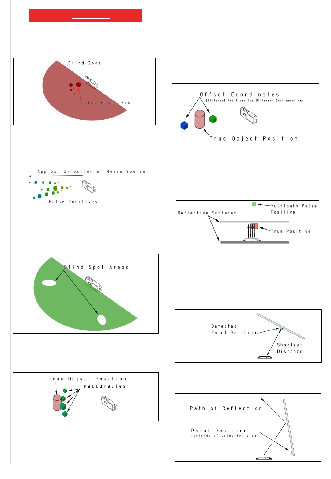
Destructive interference can occur under certain circumstances. This
results in areas, not covered by the sensor. Those areas are of limited
spacial expansion of 10 –20 cm (3.9 –7.9 in.). Those blind spots occur in
a symmetrical pattern.
Known Issues
Primary Reflections
The sensor perceives the transmission pulse as reflections in close
proximity (0-20 cm / 0-7.8 in.). This effect can be mitigated by adjusting
the of the number of pulses and peak window size.
False Positives
Interfering echoes, environmental noise and other ultrasonic sources
are visible as false positives. Depending on the duration and amplitude,
noise points can occur at random positions.
Blind Spot Areas
The calculated position of an echo is dependent on the reflected signal
strength received by the sensor. Less energetic signals result in higher
positional variance up until the point of imperceptibility.
Accuracy Issues
These errors can be mitigated by adjusting the echo rejection threshold
to a higher value, with the disadvantage of a diminished detection
range and a smaller opening angle.
In the presence of continuous environmental noise, the system will
wait until noise contamination falls below an acceptable threshold
and trigger the next measurement. This will lead to missing frames
which in turn reduces the output refresh rate. Configurations with a
low echo rejection threshold are more prone to this behaviour.
Refresh Rate Drops
The reflective properties of the target object can influence the detected
echo position.
•Big planar objects (e.g. Walls) will reflect a single echo on the
surface of the object with the closest proximity to the sensor.
Target Angle
•Big planar objects (e.g. Walls) at certain angles will reflect most of
the acoustic energy away from the sensor. Possible detectable
positions can be located outside of the field of view of the sensor.
7
Preliminary Prototype | All right reserved | All Information without warranty
Calibration Issues
The calculated position of an echo is depending on the sensor
configuration. The pulse length as well as the selected peak detection
window size will add an offset to the actual coordinates.
Multipath Reflections
An echo, which is reflected multiple times between two surfaces e.g. in
close proximity with the sensor placed in between, will produce false
positives .

Arduino to Sensor Pin Connection
Sensor Connector Pin Arduino Pin
Contact No. 1: Not Used (GND) -
Contact No. 2: TX Sensor Side Pin 7: RX Arduino Side
Contact No. 3: RX Sensor Side Pin 8 : TX Arduino Side
Contact No. 4: Ground GND: Arduino Ground Connection
Contact No. 5: Voltage 3.3 V Vcc: Arduino 3.3V Connection
The Arduino library uses Serial1 to connect to the PC and Serial2 to
connect to the sensor. If two sensors are used, Serial3 of the Teensy 3.2
can be connected (Pin 9 for Arduino RX and Pin 10 for TX).
It should be noted that this setup requires polling mode for both
connected sensors to avoid interference.
Arduino Connection
The sensor can be connected to an embedded system via serial
connection. This example shows the connection to a Teensy 3.2 board.
This board was chosen due to the high baud rate necessary. The TS3
Sensor is not compatible with low speed MCUs like the Arduino UNO.
Application Note
Arduino Library
The sensor prototype is not certified under FCC/CE regulations. An EMC
measurement was conducted in a certified test institute to ensure
electromagnetic compliance.
Compliance is heavily dependent on the cable and MCU/PC used with
the TS3-Sensor.
For the following measurements, the USB-Connection was used in
combination with an USB-Power-Bank.
8
Preliminary Prototype | All right reserved
EMC-Analysis
The serial connection is not 5 V tolerant
Contact
Table of contents
Other Toposens Accessories manuals


Popular Accessories manuals by other brands

Sports Attack
Sports Attack JUNIOR HACK ATTACK instruction manual

Vernier
Vernier Go Direct Acceleration manual

Moog Videolarm
Moog Videolarm IPRS01 Installation and operation instructions

CARLO GAVAZZI
CARLO GAVAZZI PVS1V manual

Ghibli & Wirbel
Ghibli & Wirbel SANIPRO 20.12 AP Use and maintenance

Honeywell
Honeywell TC840MFE Installation and maintenance instructions


