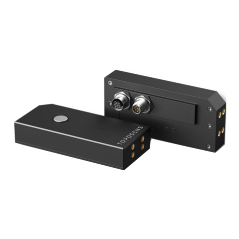
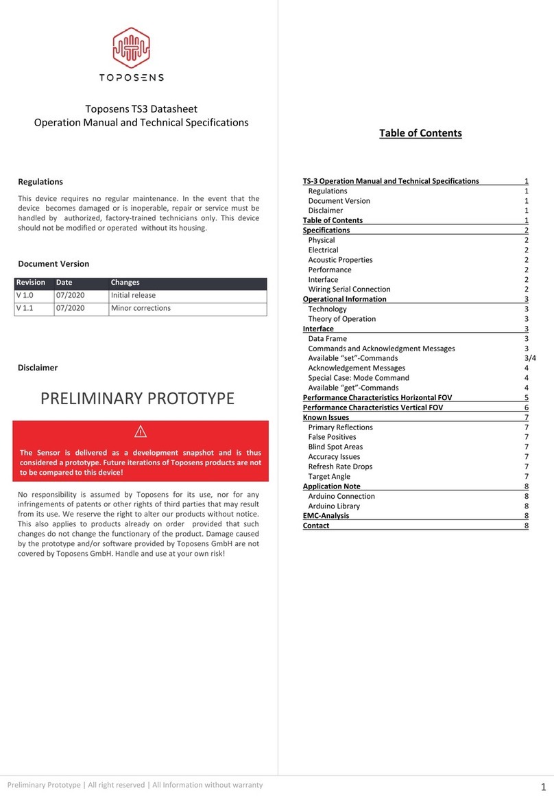
Toposens TS3 User manual

Toposens TS3-Sensor Configuration
Guide
Disclaimer of Liability
This document could include technical or other mistakes, inaccuracies
or typographical errors.We may make changes to the software or
documentation at any time without prior notice.
This document may be out of date, and we do make no commitment in
updating the materials.
Document Version
Rev
ision
Date
Changes
V 1.0
0
8/2020
Initial release
PRELIMINARY PROTOTYPE
The Sensor configuration changes the behavior and the data quality.
The Sensor can not be damaged by configuration.
1
Toposens TS3-Visualizer Operation Manual and Documentation 1
Disclaimer of Liability 1
Document Version 1
Table of Contents 1
Configuration 2
Explanation of Sensor Functionality 2
Graphic Explanation 3
Number of Pulses 3
Echo Rejection Threshold 4
Peak Detection Window 5
Configuration Parameter Interaction 6
Table of Contents
Preliminary Prototype | All right reserved | All Information without warranty

Configuration
The flexible sensor configuration enables the adaption of the systems detection properties to a wide variety of possible use case
applications and environmental situations. Those parameters can be comfortably adjusted in the TS3-Visualizer and via serial
commands.
2
Preliminary Prototype | All right reserved | All Information without warranty
Echo
Rejection Threshold
Command
sReje
Effect
Sets
the minimum amplitude for echoes above which they are considered valid detections. A low value
will
result
in a higher number of detections but also a higher probability of false detections
Parameter
5
-digit unsigned integer representing the threshold
Applicable
Values
Default
= 1, min. = 0, max. = 20
Example
CsReje
00001\r for a threshold offset of 1
Number
of Pulses
Command
sPuls
Effect
Sets
number of ultrasonic pulses emitted by the piezo transducer in each transmission cycle. Increasing
the
value
will allow the detection of objects that are further away, decreasing it will increase the quality
of
detections
in close range
Parameter
5
-digit unsigned integer representing the number of pulses to be sent out
Applicable
Values
Default
= 8, min. = 0, max. = 20
Example
CsPuls
00010\r for 10 pulses
Peak
Detection Window
Command
sPeak
Effect
Sets
the kernel size (window width) that is applied on raw ADC signals to detect valid echoes (peaks in the
raw
ADC
signal). A low value will allow for better separation of multiple objects that are close to each other. A
high
value
will result in "smoother" and more stable detections
Parameter
5
-digit unsigned integer representing the size of the the object filter
Applicable
Values
Default
= 3, min. = 1, max. = 5
Example
CsPeak
00003\r for size of 3
Sensor Functionality Explanation
[1] the transducer (red) sends out an ultrasonic pulse,
[2] the wave is carried forward by the air molecules,
[3] the wave is reflected by an object, [4] a portion of
the echo is directed back to the sensor, [5] the echo is
sequentially captured by the microphone array,
arriving first at (a) the left microphone, and then at (b)
the right microphone, [6] a 3D location of the echo’s
origin (light red) is determined from the signal’s time-
of-flight and the delay between microphones
receiving the echo.
The algorithmic parameters exposed for user manipulation change the sensitivity, selectivity and stability of the point cloud. While
it is possible to set all parameters to high values or use the trial and error method the following explanations seek to help the user
to understand the influences.

Graphic Explanation
Number of Pulses
The most comprehensible modifiable value is the length of the transmitted acoustic signal. Due to the resonance of the
transducer, longer signals equal a higher power for the transmission signal. This directly impacts the maximum detection distance
of the system. Longer pulses with higher amplitude can result in lower accuracy.
3
Preliminary Prototype | All right reserved | All Information without warranty
Number
of Pulses
Command
sPuls
Effect
Sets
number of ultrasonic pulses emitted by the piezo transducer in every transmission cycle. Increasing
the
value
will allow the detection of objects that are further away, decreasing it will increase the quality
of
detections
in close range
Parameter
5
-digit unsigned integer representing the number of pulses to be sent out
Applicable
Values
Default
= 8, min. = 0, max. = 20
Example
CsPuls
00010\r for 10 pulses
The transmission signal length influences the maximum detection distance, the returned signal strength and the selectivity. Longer
signals carry more power but also fuse smaller object in close proximity to the sensor.
To visually demonstrate the influence of the parameters, the following substitute graphic is used. The red arrow indicates the
sensor position and heading, while the red dots show the actual object positions (e.g. pole or sphere in this case). The size of the
red circles indicate the size of the real objects while the grey circles indicate the sensors perception of the acoustic reflection. Less
visible, brighter colored circles indicate less “loud” echoes. In the following explanations, a single parameter is changed at a time.
Short (1-3) = Low Amplitude/Length Signal
Medium (4-7) = Medium Amplitude/Length Signal
Large (8-20) = Large Amplitude/Length Signal
Short signals result in better discrimination
properties regarding close ranged
detection of objects. Objects in a further
distance can’t be detected if the reflected
energy is lower than the configured
threshold.
Medium signals are the best all round fit
for most use cases. Objects at a further
distance have a chance of being detected,
while close objects can still be recognized
as separate ones.
Large signals enable the recognition of
objects farther away from the sensor.
Please note the “fusion” of close ranged
objects due to the loud and long
transmission pulse. This effect can’t be
compensated for by other parameters.
The size of the circles indicates the
detected position of the echo. Bigger
circles indicate less accuracy while
the brightness indicates echo signal
integrity.
If the circles are fusing, this indicated
possible echo interference which
results in inaccurate detection.

Echo Rejection Threshold
4
Preliminary Prototype | All right reserved | All Information without warranty
The Echo Rejection Threshold configuration parameter describes the lower cutoff, which tells the sensor the minimum amplitude
of received echoes to be processed. Due to the automatic noise reduction, this value is not equal to the points volume value.
Echo
Rejection Threshold
Command
sReje
Effect
Sets
the minimum amplitude for echoes above which they are considered valid detections. A low value
will
result
in a higher number of detections but also a higher probability of false detections
Parameter
5
-digit unsigned integer representing the threshold
Applicable
Values
Default
= 1, min. = 0, max. = 20
Example
CsReje
00001\r for a threshold of 1
Low (0-1) = Low Amplitude Threshold
Medium (2-4) = Medium Amplitude Threshold
Medium (5-20) = High Amplitude Threshold
Low values for the echo rejection
threshold result in lots of instable
points. Those points are not
necessarily noise but small
reflections which can not be
located continuously.
Medium values allow for the
most versatile sensor
configuration. Noise is not as
prominent as with lower values,
but false positives can still occur.
High threshold values enable the
detection of larger objects at
medium distances with almost
no false positives. Please note
the rate for false negatives is
increased.
Due to the prototype characteristic of the sensor, the sensors threshold is of a linear nature and will not adjust to the
measured distance.
False Positives
False Negative
Threshold settings of 0 are not recommend due to noise issues. Settings between 2 and 5 have the biggest impact.

Peak Detection Window
5
Preliminary Prototype | All right reserved | All Information without warranty
The Peak Detection Value defines the length of echoes processed into a single object. This value enables the fusion of complex
surfaces into less points. Additionally noise can be filtered out even when using small echo detection thresholds. Additionally the
stability of the point detection is enhanced due to more echo location data being processed.
Peak
Detection Window
Command
sPeak
Effect
Sets
the kernel size (window width) that is applied on raw ADC signals to detect valid echoes (peaks in the
raw
ADC
signal). A low value will allow for better separation of multiple objects that are close to each other. A
high
value
will result in "smoother" and more stable detections
Parameter
5
-digit unsigned integer representing the window width size of the the object filter
Applicable
Values
Default
= 3, min. = 1, max. = 5
Example
CsPeak
00003\r for size of 3
Please note the tendency of smaller objects to fuse when higher values are configured. Smaller objects with similar relative
position to the sensor as bigger objects are fused with the bigger object. Note that each object fusion will change the resulting
coordinates of the bigger objects weighted by the amplitudes of both objects. Smaller objects in close proximity to bigger objects
tend to disappear if the window size is set to values above 2.
Small (1-2) = Small Window Size
Medium (3-4) = Medium Window Size
Large (5) = Large Window Size
The Small and Medium
configuration fits best for
most purposes. A value of
1is best for close range
applications.
On the Medium
configuration small
objects with proximity to
bigger objects can fuse.
The Large window setting
is fusing even bigger
objects. It can be used for
distance detection to
avoid noise.

Configuration Parameter Interaction
6
Preliminary Prototype | All right reserved | All Information without warranty
The parameter interaction can not be described in full detail. To give an overview reasonable high values are combined with
reasonable low values to show the influences of the parameter interaction to the resulting point cloud. In application cases a
combination of minimum and maximum values as showed below is not feasible. Medium values work best for most use cases.
No. Pulse Thre. Win. Example
1-
(1-3)
-
(0-1)
-
(1)
2+
(8-12)
-
(0-1)
-
(1)
3-
(1-3)
+
(5-10)
-
(1)
4+
(8-12)
+
(5-10)
-
(1)
5-
(1-3)
-
(0-1)
+
(5)
6+
(8-12)
-
(0-1)
+
(5)
7-
(1-3)
+
(5-10)
+
(5)
8+
(8-12)
+
(5-10)
+
(5)
In this configuration, noise will be visible while small
objects can be detected and differentiated. Use this or a
similar configuration if close range detection of small
objects is needed.
Noise will be clearly visible while objects at all distances
are detected. Useful for outdoor / clear space use cases
with all sizes of objects. Additional post processing likely
needed to filter noise.
This setting is enabling the lowest false positive rate
while increasing the false negative rate. Good for
medium distance obstacle avoidance. Small objects are
likely to be ignored if not close to the sensor.
Low noise level combined with a reasonable detection
area. Due to the high pulsed volume, accuracy issues
may occur.
Due to the high peak detection window, noise level are
low. Objects can be detected but in general this setting is
a valid option for close range detection.
The long signal in combination with the large peak
detection window causes a higher number of fusion
between objects in close proximity. Good for outdoor /
free space use cases with big objects and low noise
levels.
The small signal in combination with the restrictive filters
results in less points (more false negatives) while being
less accurate due to the low amplitude signal.
All max setting. Not recommended for most use cases
but sometimes useful for human interaction (Gesture
control, People Detection).
The following parameter combinations are exaggerated to show comprehensible configuration results.
Table of contents
Other Toposens Accessories manuals
Popular Accessories manuals by other brands

X-dream Fly
X-dream Fly X-TRIANGLE Operation manual
Transmitter Solutions
Transmitter Solutions IGAZE iGAZER45P installation manual
BRUEL & KJAER
BRUEL & KJAER ASA-069 Series manual
Dell
Dell PowerVault 114T 2U Read this first

anko
anko 43235681 user manual

Porter
Porter 1535 Assembly, Adjustment, Operation & Maintenance Manual
