Topp Music Gear VA Series User manual

VA42BM / VA42TP / VA-WP
VA12SA

2
Important Safety Instructions

3
Table of Contents
1. INTRODUCTION
2. FEATURES
3. USEFULL DATA
4. QUICK START
5. CONNECT MANNER
6. BACK PANEL DESCRIPTION
7. CONNECTION PLATE SYSTEM
8. FREQUENCY RESPONSE DIAGRAM
9. WIRE CONNECTIONS
10. TECHNICAL SPECIFICATIONS
11. GUARANTEE
12. NOTES
4
4
4
5
6
7
8
10
11
12
14
15

4
Introduction
1
2
3
Thank you for choosing TOPP PRO. The new TOPP PRO MUSIC GEAR cabinets have been
designed to provide a cost effective high grade solution while maintainig high quality cabinet
construction and optimum components.
Our Professional Audio Products are designed and tested by a highly qualified engineering team
with more than 20 years of experience. Great care is placed in delivering products with excellent
performance, specifications and dependable reliability. Also great emphasis is placed in creating
and bringing to market products that can fill multiple applications and also offer customers
exceptional value.
Every TOPP PRO audio product is strictly tested and complied to very strict standards.
Speakers should be placed in a position that allows for unobstructed sound projection. In many
instances it is beneficial for speakers to elevate on tripod stands to achieve maximum dispersion
and reach. Consider TOPP PRO speaker stand or equivalent to raise speakers.
Using quality cables ensure best possible sound. Consider using TOPP PRO 16 or 14 gauge
cables or equivalent.
For best results match the speakers to a good amplifier that matches the wattage and
impedance of your speakers. Proper amplification power results in good quality audio and
longer component life. Check out.
Avoid pointing microphone directly at an amplified speaker otherwise could cause feedback
possible damaging speaker components and your hearing.
Installation Tips

5
4
Quick Start
When mounting a speaker onto any stand, always ensure that the stand is on a flat, level
sur-face, with the legs fully extended. Be sure to check that the maximum load weight for the
stands is greater than the weight of the ARRAY SYSTEMS loudspeaker. Never use a stand with a
maximum load weight lower than the speaker. Do not attempt to mout more than one speaker
on a stand at one time.
The ARRAY SYSTEMS loudspeakers are heavy. It is recommended that a second person to help
place the cabinet on a stand.
When the speaker is placed on a stand, always check the integrity and center of gravity of the
system If the speaker can be tipped easily, or the pole is swaying, it is recommended that you
lower the height of the stand. Position the stand and route cables so that the performers and the
audience cannot tip over or trip on the system.
VA42TP
VA42BM
VA-WP
VA12SA

Connect Manner
5
6
Insert the 4 PCS of fixed legs of VA-WP into the fixed seat of SUB, It means the assembly and
connection of signal cable completed, details as below picture#1.
Snap the slot-terminal holder of VA42BM into the upper protruding holder of VA-WP, and
then push VA42BM into slots along the opposite direction of grill. It means the assembly and
connection of signal cable completed. details as below picture #2.
Snap the slot-terminal holder of VA42TP into the upper protruding holder of VA42BM, and
then push VA42BM into slots along the opposite direction of grill. It means the assembly and
connection of signal cable completed . details as below picture #3.
Once assembly completed, no extra signal cable needed, based on the needs, user can rotate
VA42BM / VA42TP towards left or right within 90 degree limit.
1
2
3
4
#1
#2
#3

6
7
BACK PANEL DESCRIPTION
1) AC POWER SOCKET WITH MAIN FUSE.
2) ON-OFF MAIN POWER SWITCH.
3) MP3 PLAY
4) CONVECTION FAN
5) IP CONTROL
6) THRU OUTPUT ON XLR CONNECTOR
This is a male XLR-type connector that produces exactly the same signal that is connected to the main
input jack or a mix of input1 and input2.
7) CENTER/OPEN/USER
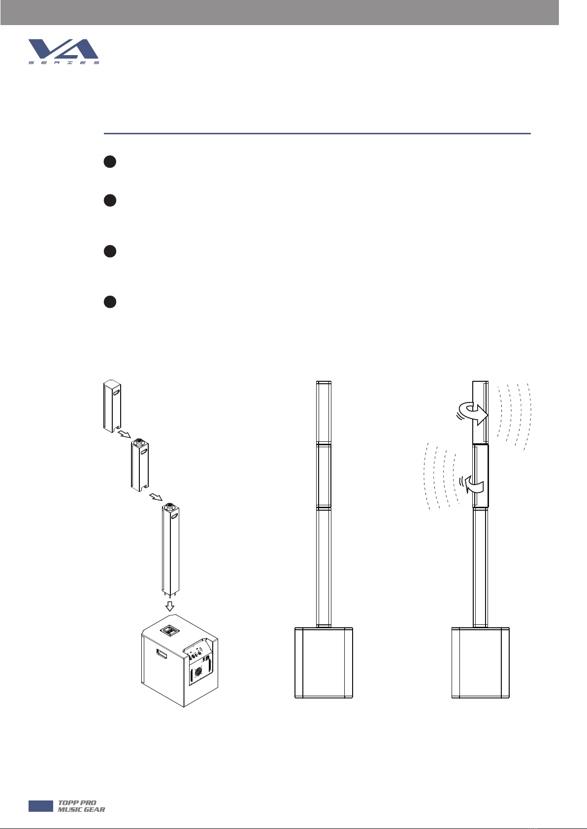
CENTER:Allow use this subwoofer with the 2 satellite(VA42TP and VA42BM).Defaults factory
preset for Both satellites never rotate and keep grill towards front
OPEAN: Allow use this subwoofer with the 2 satellite(VA42TP and VA42BM). Defaults factory
preset for the VA42TP (or VA42BM)turn 45 degree towards left,another turn 45 degree towards
right.
8) SWITCH FOR FRONT LED ON OR OFF
9) POWER. GREEN LED, INDICATE ON STATUS.
10) SIGNAL / LIMIT, RED LED, INDICATE ON STATUS.
11) INPUT2 ON COMBO CONNECTOR.
12) LINE / MIC SWITCH(CHANNEL INPUT1 ONLY)
13) LINE / MIC INPUT1 ON COMBO CONNECTOR.
14) XLR AND 1/4” COMBO INPUT2
INPUT2 may accept Hi-Z sources (such as guitars) via the TRS 1/4” input, or line-level signal via XLR.
NEVER connect the output of an amplifier directly to the input of the loudspeaker. This could damage
the input circuitry of the active loudspeaker.
15) XLR AND 1/4” COMBO INPUT1
INPUT1 may accept a MIC or line-level signal via XLR or line-level signal via TRS 1/4” cable.
Be aware of the position of the MIC / line switch (12).
16) RCA INPUTS (INPUT2 ONLY).
17) INPUT1 / MIX SWITCH (THRU OUTPUT)
This switch allows you to choose whether only the input1 signal is sent out to the next
loudspeaker(switch out-input1) or mix of the input1 and input2 signals are sent out to the next
loudspeaker(switch in-Mix).

CONNECTION PLATE SYSTEM
7
8
Make your initial connections with all the equipment powered off, and ensure that all the
main volume controls are turned completely down.
1) Connect one side of the signal cable at your audio mixer into output left / right (with
Stereo-Jack or XLR) and the other side of the cable into the line input (Stereo-Jack) of your active
speaker cabinet.
2) Connect the power cord to mains.
3) Turn on your mixer first, then the active speaker cabinets.
4) Turn up the volume control of the active speaker cabinets.
5) Use PFL function to get the proper input level for the mixer, and adjust the Main Mix Level
control to manipulate the output level.
6) After using, turn off your stereo power amplifier first, then the mixer.
Pole Pole
Signal Cable
Mixer
Signal Cable
Left
Main Mix
Output
Right
Main Mix
Output

9
CONNECTION PLATE SYSTEM
Make your initial connections with all the equipment powered off, and ensure that all the main
volume controls are turned completely down.
Two Active Subwoofers & Two Passive Satellite Speakers
1) Connect one side of the signal cable to the output of your mixer (left / right) with a TRS or
XLR connector and the other side of the cable to the line input (combo) in the active
subwoofer (with a TRS to XLR connector). Then connect the speakon cable from the output
of power in the Subwoofer to the satellites input.
2) Complete other connections as illustrated.
3) Turn on your mixer first, then the stereo power amplifier.
4) Turn up the volume controls of your amplifier to about70%.
5) Use PFL function to get the proper input level for the mixer, and adjust the Mian Mix Level
control to manipulate the output level.
6) After using, turn off your stereo power amplifier first, then the mixer.
Pole Pole
Signal Cable
Mixer
Signal Cable
Left
Main Mix
Output
Right
Main Mix
Output
7

10
8FREQUENCY RESPONSE DIAGRAM
VA SYSTEM

11
9
WIRE CONNECTIONS

12
TECHNICAL SPECIFICATIONS
10
VA42BM
3.5" Passive Speaker System
120W Continuous, 240W Program, 480W Peak
95dB
122dB Max.(calauated)
160Hz-20kHz
8 ohms
4 x 3.5'' Woofer , 1.0'' (25.4mm) Voice Coil
500Hz
100°Horizontal
Adjustable Rigging System, Horizontal Splay Rotation in
-90°-0°- 90° Increments from 180°
Parallel or Series φ6.3mm Socket / Selection Switch
Plywood Cabinet, Resistant Paint, Metal Grille with Foam
2 x Holder,1 x Input Connector for AX Pole, Another with
Input Connector for AX V42TP
448*106.6* 98mm(17.64'' x 4.20'' x 3.86'')
3.48Kg (7.67 Ibs)
Passive Speaker
System Type
Output Power
Sensitivity (1W/1M)
Maximum SPL @ 1m
Frequency Response(-6dB)
Impedance
Transducer Low
Crossover Frequency
Dispersion(-6dB)
Attachment Points
Connectors
Enclosure Construction
Mounting
Dimensions (HxWxD)
Net Weight
Passive Speaker
System Type
Output Power
Sensitivity (1W/1M)
Maximum SPL @ 1m
Frequency Response(-6dB)
Impedance
Transducer Low
Crossover Frequency
Dispersion(-6dB)
Attachment Points
Connectors
Enclosure Construction
Mounting
Dimensions (HxWxD)
Net Weight
VA42TP
3.5" Passive Speaker System
120W Continuous, 240W Program, 480W Peak
95dB
122dB Max.(calauated)
160Hz-20kHz
8 ohms
4 x 3.5'' Woofer , 1.0'' (25.4mm) Voice Coil
500Hz
100°Horizontal
Adjustable Rigging System, Horizontal Splay Rotation in
-90°-0°- 90° Increments from 180°
Parallel or Series φ6.3mm Socket / Selection Switch
Plywood Cabinet, Resistant Paint, Metal Grille with Foam
1 x Holder,1 x Input Connector for AX V42BM or AX Pole
422*106.6* 98mm(16.61'' x 4.20'' x 3.86'')
3.41Kg (7.52 Ibs)

13
10
TECHNICAL SPECIFICATIONS
Pole
Enclosure Construction
Mounting
Dimensions(WxHxD)
Net Weight
Plywood Cabinet, Resistant Paint, Metal Grille with Foam
2 x Holder,1 x Input Connector for Sub, Another with Input
Connector for Satellite
700*106.6* 98mm(27.56'' x 4.20'' x 3.86'')
2.70Kg (5.95 Ibs)
VA-WP
VA12SA
12" Active Subwoofer Speaker Cabinet
40 Hz – 500 Hz
1000 W Continuous/2000W Program/4000W Peak Class D @ 4 Ohms
500 W Continuous/1000W Program/2000W Peak Class D @ 4 Ohms
Center / Open / User
96dB
130dB Max(Calculated)
Over heat Protection / Short Circuit Protection / Digital Compressor
Temperature-controlled fan
Input: 2 Combo-XLR&1/4”, RCA In L&R, 1 XLR Thru&Mixout
Volume Control/Switch for Input sens/Swtich for mode selector/Power
ON with Green LED/Limiter with Red LED/Ground Lift/IP Control/MP3/
BT Player
110V/230V ~50/60Hz
Plywood Cabinet,Resistant Black Paint, Metal Grille with Foam,
Rubber Feet,Integrated side handles
Holder with Input Jacks for Pole
379*500* 473mm (14.92'' x 19.69'' x 18.62'')
21.5Kg (47.40 Ibs)
Active Subwoofer
System Type
Frequency Response(-6dB)
Total Amplifier Power
Amplifier, Subwoofer
Amplifier, Satellite
DSP Presets
Sensitivity (1W/1M)
Maximum SPL@1M
Electronic Protections
Cooling
Connections
External Controls
Power Supply
Enclosure Construction
Mounting
Dimensions(WxHxD)
Net Weight

14
11 GUARANTEE

NF05206-1.0
This manual suits for next models
3
Table of contents
Other Topp Music Gear Speakers manuals