Torit Donaldson WSO 20 User manual
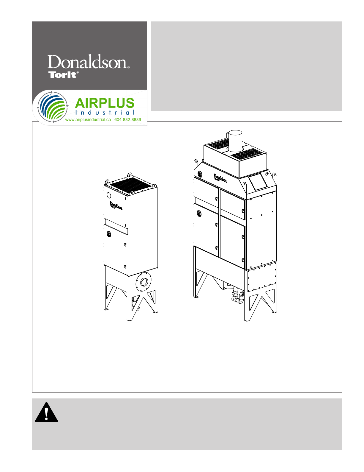
WSO 25-1 WSO 25-2
This is the safety alert symbol. It is used to alert you to potential personal injury hazards.
Obey all safety messages that follow this symbol to avoid possible injury or death.
This manual is property of the owner. Leave with the unit when set-up and start-up are complete. Donaldson Company reserves the right to
change design and specifications without prior notice.
Illustrations are for reference only as actual product may vary.
WSO Mist Collector
WSO 20, 25-1, 25-2 and 25-3
Installation and Operation Manual
Installation, Operation, and Service Information
IOM AD3616801 (ENG)
Revision 4
English
Master Language
i
Donaldson Company, Inc.
Model Number _____________________________ Serial Number ______________________________
Ship Date _________________________________ Installation Date _____________________________
Customer Name _______________________________________________________________________
Address _____________________________________________________________________________
____________________________________________________________________________________
Filter Type ____________________________________________________________________________
Accessories __________________________________________________________________________
Other________________________________________________________________________________
Data Sheet
This manual has been supplied to assist with the installation, operation and maintenance for the collector
purchased. Please read the manual before installing, operating, or performing maintenance on the collector
as it contains specific precautions for worker safety. It is the owner’s responsibility to ensure that this
manual is available for use by installers, operators and maintenance personnel that will be working with this
collector. This manual is the property of the owner and should be left with the collector when installation has
been completed. DO NOT operate this collector until you have read and understood the instruction warnings
located in this manual.
For additional copies of this manual, contact Donaldson Torit.
The Safety Alert Symbol indicates a hazardous situation which, if not avoided could result in death or
serious injury. Obey all safety messages following this symbol to avoid possible injury or death.The
possible hazards are explained in the associated text messages.
The Notice symbol indicates a potential situation or practice which is not expected to result in
personal injury, but which if not avoided may result in damage to equipment.
IMPORTANT NOTES

WSO Mist Collector, WSO 20, 25-1, 25-2, and 25-3
ii
Magnehelic®and Minihelic®are registered trademarks of Dwyer Instruments, Inc.
Contents
IMPORTANT NOTES .................................................................i
Safety Communication............................................................1
Description................................................................................3
Purpose and Intended Use ....................................................3
Rating and Specification Information...................................4
Operation...................................................................................5
Inspection on Arrival...............................................................6
Installation Codes and Procedures ......................................6
Installation.................................................................................6
Foundations or Support Framing .......................................7
Collector Location................................................................7
Site Selection .......................................................................7
Ceiling-Mounted Collectors (WSO 20 and 25-1)..............7
Rigging Instructions.................................................................8
Hoisting Information ............................................................8
Standard Equipment................................................................9
Provisional Anchor Bolt Recommendations....................9
Typical Floor Mount Installation ........................................9
Ceiling Mount (WSO 20 and 25-1)...................................11
P-Trap Installation..............................................................12
Inlet Collar Installation ......................................................12
Electrical Wiring.................................................................13
Preliminary Start-Up Check .................................................14
Motor Starter Control Box ................................................14
Maintenance Information.....................................................15
Operational Checklist ........................................................15
Filter Removal and Installation.........................................15
First Stage Filter Cleaning and Installation ................15
Primary Filter Installation ..............................................16
Final Filter Installation (WSO 20 and 25-1)..................17
Final Filter Installation (WSO 25-2 and 25-3) ..............17
P-Trap Service ....................................................................18
P-Trap with Y-Strainer, Screen Cleaning and Removal18
Drain Collection Container................................................19
Optional Equipment................................................................20
Fan Blower ..........................................................................20
Factory-Installed HEPA/95% DOP Filter..........................20
Field Installation Afterfilter (WSO 20 and 25-1).............20
Magnehelic®or Minihelic® Installation.........................21
Remote-Mount Magnehelic Installation ........................21
Damper and Silencer, TBI.................................................23
Sprinkler...............................................................................24
Troubleshooting......................................................................25
Service Notes.........................................................................27

1
Donaldson Company, Inc.
Improper operation of dust collectors and/or dust control systems may contribute to conditions in a work
area or facility which could result in severe personal injury, and product or property damage. All dust
collection equipment should be used only for its intended purpose and should be properly selected and sized
for its intended use.
Process owners have important responsibilities relating to identifying and addressing potential hazards
in their processes. When the potential for handling combustible dust exists within a process the process
owner should include combustion hazards in their risk management activities and should comply with
applicable codes and standards related to combustible dust.
Electrical installation must be performed by a qualified electrician.
This equipment is not designed to support site ducts, piping, or electrical services. All ducts, piping, or
electrical services must be adequately supported to prevent injury and/or property damage.
Site selection must account for wind, seismic zone, and other load conditions.
Equipment may reach peak sound pressure levels above 80 dB (A). Noise levels should be considered when
selecting collector location.
Combustible Dust Hazards
Among other considerations, the current NFPA standards require owners whose processes involve
potentially combustible materials to have a current Dust Hazard Analysis, which can serve as the foundation
for their process hazard mitigation strategy. Mitigation may include but is not limited to:
Prevention of all ignition sources from entering any dust collection equipment.
Selection and implementation of fire and explosion mitigation, suppression, and isolation strategies
appropriate for the risks in their process.
Development and use of work practices to maintain safe operating conditions, and to ensure combustible
dust does not accumulate within their plant.
Donaldson recommends process owners consult experts in combustion risks to ensure these responsibilities
are met. Some processes may involve materials or processes which have inherent fire and explosion
hazards. The process owner retains responsibility to comply with applicable codes and standards and
to manage the risks associated with the process or materials. Donaldson is neither an expert nor a
certified consultant in fire, spark, or explosion detection, suppression, or control. Donaldson does not
provide engineering consulting services related to process or dust hazard analyses, or code and standard
compliance.
Donaldson may provide referrals to consultants and/or suppliers of equipment or services related to the
detection and/or mitigation of sparks, fires and/or explosions, but Donaldson does not assume responsibility
for any such referrals, nor does Donaldson assume any liability for the fitness of a mitigation strategy or
product for a particular installation or application. The process owner’s final selection of dust collection
and risk mitigation strategies should be based on the outcome of a Dust Hazard / Process Hazard Analysis
performed by the process owner. Although early engagement of a dust collector supplier can provide helpful
insights on the availability and features of various products, process owners should consult with combustible
dust experts and/or process safety experts before making actual product and mitigation strategy selections.
Safety Communication

WSO Mist Collector, WSO 20, 25-1, 25-2, and 25-3
2
Donaldson recommends all industrial air filtration system designs be reviewed and approved by an expert
consultant responsible for the integrity of the system design and compliance with applicable codes and
standards. It is the process owner’s responsibility to understand risks in their process and mitigate those
risks in accordance with all applicable laws, regulations and standards, including those published by the
NFPA. Donaldson also recommends proper maintenance and housekeeping procedures and work practices
be evaluated, developed, and followed to maintain any industrial air filtration products in safe operating
condition.
Many factors beyond the control of Donaldson can affect the use and performance of Donaldson products
in a particular application, including the conditions under which the product is used. Since these factors are
uniquely within the user’s knowledge and control, it is essential the user evaluate the Donaldson products to
determine whether the product is fit for the particular purpose and suitable for the user’s application.

3
Donaldson Company, Inc.
Designed for versatility, the WSO (Water, Smoke, and Oil)
mist collector is specifically engineered for water-based,
smoke, and oil-based mist applications. WSO mist
collector, Models WSO 20, 25-1, 25-2, and 25-3 collect
airborne mist such as oil, water-soluble, semi-synthetic
and synthetic coolant from machining operations. Two
stages of filtration, plus an optional HEPA or 95% DOP
filter, provide a cleaner, healthier work environment as
well as a more cost effective means of mist collection.
With maximum airflow capacities up to 2,000 cfm for
WSO 20 and 25-1 and 5,500 cfm for WSO 25-2 and 25-3,
the WSO is a strategic component to meeting industrial
and government air-quality standards. The high
efficiency filter cartridges allow air and coolants to be
recycled.
Designed to increase the versatility of the collector,
a variety of filter media specifically designed for mist
collection is a standard offering on the product line. The
WSO 20 contains a 20 inch tall primary filter and the
WSO 25-1, 25-2, and 25-3 contain a 25 inch tall primary
filter uniquely designed for either water-based coolants,
straight oils, or thermally-generated smoky applications.
Standard options include drain collection containers,
P-Traps, and afterfilters.
WSO models 20 and 25-1 include the blower and motor.
WSO models 25-2 and 25-3 are available with or without
a blower and motor.
Airborne mist is small droplets of metalworking fluids
suspended in the air. Metalworking fluids include
straight oils, water-soluble coolants, semi-synthetic and
synthetic coolants. These fluids perform a variety of
functions such as lubricating or cooling the part or the
tool, flushing chips away from the part, and suppressing
dust and smoke.
Mist is created two ways: mechanical action or thermal
effects. Mechanical action involves coolant used for
light lubrication and generally creates mist greater than
one micron in size. Thermal effects occur when heat
vaporizes the coolant, the vapor cools and recondenses
into a mist. Thermal effects create mist from 0.01 to 1
micron in size. Other contaminants, such as dust from
the part or the tool or smoke from the vaporization
of the oil or coolant are also generated when using
metalworking fluids.
The WSO mist collector is not designed to handle water
mist alone. There should be some type of oil content
to allow coalescing or water vapor will simply pass
through the filters. The extremes of very heavy oil and
light, thin oil should be avoided. Very heavy oil, similar
to tar consistency, will not drain while very light, thin oil,
similar to paint thinner consistency, may evaporate.
Description Purpose and Intended Use
Misuse or modification may result in severe
personal injury and/or property damage.
Do not misuse or modify.
WSO Mist Collector, WSO 20, 25-1, 25-2, and 25-3
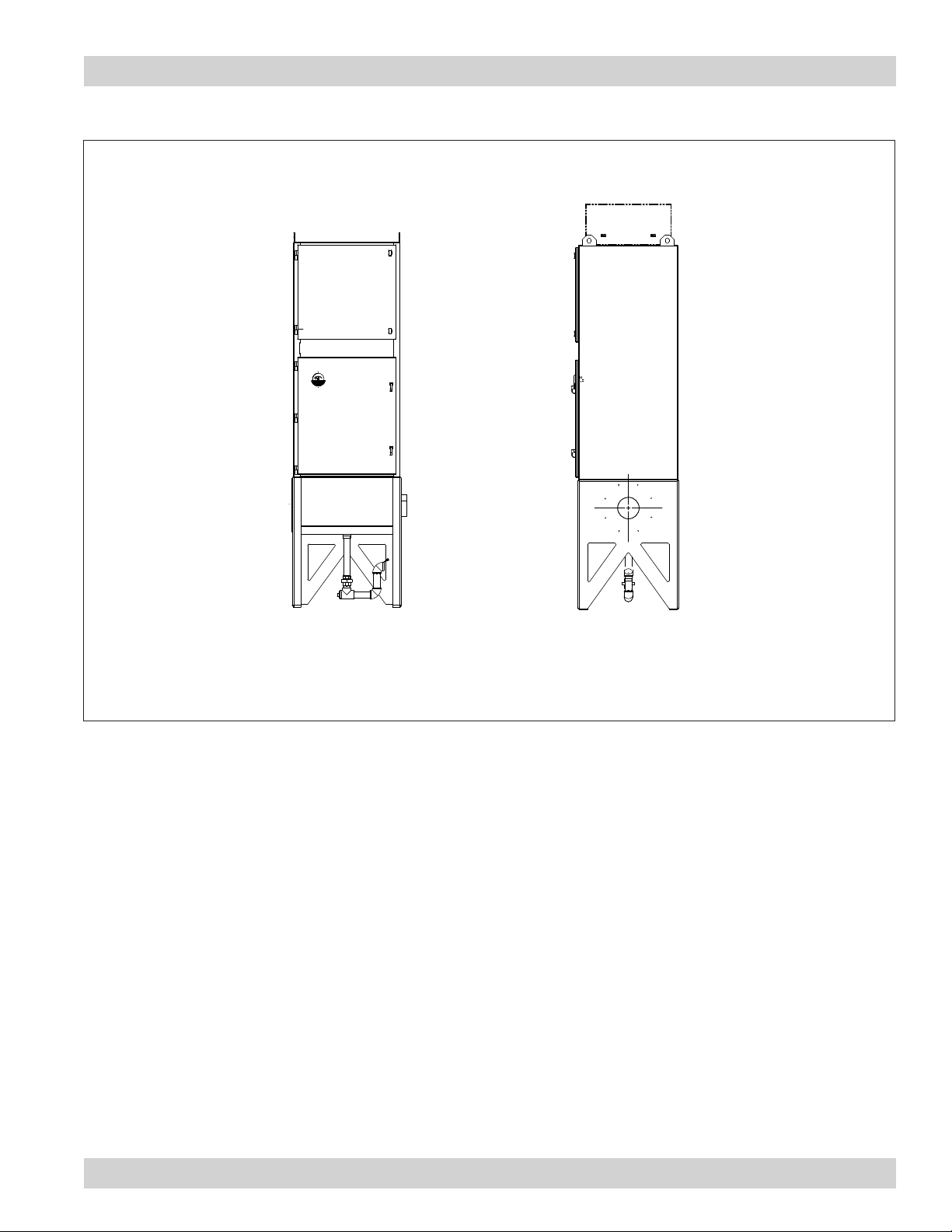
4
Front
WSO 25-1
Typical Side View
WSO 25-1
Rating and Specification Information
Collectors are rated for the following loads as calculated per relevant sections of the IBC 2006 code*:
Seismic Spectral Acceleration, Ss.......................................................1.5 g
Seismic Spectral Acceleration, S1.......................................................0.6 g
Installed Unit Base Elevation..............................................................Grade
Occupancy Category..................................................................................1.0
Housing rating, inches water gauge ..................................................... - 20
Power and controls ............. 208-Volt, 230/460-Volt, 575-Volt, 3 Ph, 60 Hz
*If collector was supplied with a Record Drawing, the specifications on the drawing will supersede the standard
specifications above.

5
Donaldson Company, Inc.
primary filter cartridge
clean-air outlet
coalesced
large droplets
first-stage filter
dirty-air inlet
clean-air plenum
blower and motor
p-trap (drain)
optional afterfilter
Collector Operation, WSO 25-1 shown
During normal operation, contaminated air enters the
collector through one or both dirty-air inlets located
on each side, toward the bottom of the collector. The
incoming air slows and turns upward, causing large
mist droplets and particles to fall out of the air stream
and into the hopper. The air passes through a reusable
first-stage filter designed to collect and coalesce large
droplets and particles.
The primary stage of filtration is the pleated filter
cartridge specifically designed to collect, coalesce, and
drain fine mist. As the mist coalesce, the droplets are big
enough to run down the cartridge and drain back into
the collector. The droplets will drain on both the inside
and outside of the cartridge. Liquid that collects on the
inside of the cartridge drains through the bottom portion
of the porous media and into the hopper. Clean, mist-free
air exits the cartridge and discharges through the top of
the collector.
Operation

WSO Mist Collector, WSO 20, 25-1, 25-2, and 25-3
6
Inspection on Arrival
1. Inspect collector upon delivery.
2. Report any damage to the delivery carrier.
3. Request a written inspection report from the Claims
Inspector to substantiate any damage claim.
4. File claims with the delivery carrier.
5. Compare collector received with description of
product ordered.
6. Report incomplete shipments to the delivery carrier
and your Donaldson Torit representative.
7. Remove crates and shipping straps. Remove loose
components and accessory packages before lifting
collector from truck.
8. Check for hardware that may have loosened during
shipping.
9. Use caution removing temporary covers.
Installation Codes and Procedures
Codes may regulate recirculating filtered air
in your facility. Consult with the appropriate
authorities having jurisdiction to ensure
compliance with all national and local codes
regarding recirculating filtered air.
Safe and efficient operation of the collector depends on
proper installation.
Authorities with jurisdiction should be consulted
before installing to verify local codes and installation
procedures. In the absence of such codes, install
collector according to the National Electric Code,
NFPA No. 70-latest edition and NFPA 91 (NFPA 654 if
combustible dust is present).
A qualified installation and service agent must complete
installation and service of this equipment.
All shipping materials, including shipping covers, must
be removed from the collector prior to or during collector
installation.
Failure to remove shipping
materials from the collector
will compromise collector
performance.
Inspect collector to ensure all hardware is properly
installed and tight prior to operating collector.
Installation
Use proper equipment and adopt all safety
precautions needed for servicing equipment.
Electrical service or maintenance work must
be performed by a qualified electrician and
comply with all applicable national and local
codes.
Turn power off and lock out electrical
power sources before performing service or
maintenance work.
Do not install in classified hazardous
atmospheres without an enclosure rated for
the application.
Site selection must account for wind, seismic
zone, and other load conditions when
selecting the location for collectors.
Codes may regulate acceptable locations for
installing dust collectors. Consult with the
appropriate authorities having jurisdiction to
ensure compliance with all national and local
codes regarding mist collector installation.
Collectors must be anchored in a manner
consistent with local code requirements.
Anchors must be sufficient to support dead,
live, seismic, and other anticipated loads.
Consult a qualified engineer for final selection
of anchorage.
7
Donaldson Company, Inc.
Ceiling-Mounted Collectors (WSO 20 and
25-1)
Lifting lugs on the unpowered collector (25-2 or
25-3) are not intended for ceiling suspension.
Collector is floor-mount only. Failure to comply
may result in personal injury and/or property
damage.
Ensure weight of oil-laden collector plus
weight of required materials and equipment
will be adequately supported. Failure to comply
may result in personal injury and/or property
damage.
WSO 20 and 25-1 can be suspended or hung from
overhead supports. The supports must be adequate
to carry the live load of the collector and installation
performed to reduce sway or vibration to the collector.
The dry collector weight is shown on the specification
control drawing shipped with the collector.
The live load will include the weight of all ancillary
hardware attached to the mist collector, as well as the
weight of the mist-laden, wet filters. Consult the coolant
MSDS for the specific gravity of the coolant to estimate
the weight of the mist-laden, wet filters.
Provide clearance from heat sources and interference
with utilities when selecting the location for suspended
collectors.
Collector Location
Donaldson Torit equipment is not designed to
support site installed ducts, interconnecting
piping, or electrical services. All ducts, piping,
or electrical services must be adequately
supported to prevent severe personal injury
and/or property damage.
When hazardous conditions or materials are
present, consult with local authorities for the
proper location of the collector.
Mist collection equipment may reach peak
sound pressure levels above 80 dB (A). Noise
levels should be considered when selecting
collector location.
Locate the collector to ensure easy access to electrical
connections, to simplify mist collection container
handling and routine maintenance, and to ensure the
straightest inlet and outlet ducts.
Site Selection
This collector can be located on a foundation or
structural framing.
Provide clearance from heat sources and avoid any
interference with utilities when selecting the location.
Foundations or Support Framing
Prepare the foundation or support framing in the
selected location. Foundation or support framing must
comply with local code requirements and may require
engineering.
Foundation and support framing must be capable of
supporting dead, live, wind, seismic and other applicable
loads. Consult a qualified engineer for final selection of
foundation or support framing.

WSO Mist Collector, WSO 20, 25-1, 25-2, and 25-3
8
Rigging Instructions
Suggested Tools & Equipment
Clevis Pins and Clamps Lifting Slings
Crane or Forklift Pipe Sealant
Drift Pins Pipe Wrenches
Drill and Drill Bits Screwdrivers
End Wrenches Socket Wrenches
Adjustable Wrench Spreader Bars
Torque Wrench (inch/lbs, 9/16-in Socket)
Hoisting Information
Failure to lift the collector correctly can result
in severe personal injury and/or property
damage.
Use appropriate lifting equipment and adopt
all safety precautions needed for moving and
handling the equipment.
A crane or forklift is recommended for
unloading, assembly, and installation of the
collector.
Location must be clear of all obstructions, such
as utility lines or roof overhang.
Use all lifting points provided.
Use clevis connectors, not hooks, on lifting slings.
Use spreader bars to prevent damage to collector’s
casing.
Check the Specification Control drawing for weight and
dimensions of the collector and components to ensure
adequate crane capacity.
Allow only qualified crane or forklift operators to lift the
equipment.
Refer to applicable OSHA regulations and local codes
when using cranes, forklifts, and other lifting equipment.
Lift collector and accessories separately and assemble
after collector is in place.
Use drift pins to align holes in section flanges during
assembly.
9
Donaldson Company, Inc.
Standard Equipment
The collector has a high center-of-gravity and
may overturn if not secured properly.
Secure the collector to the lifting device.
Use care when moving the collector.
The WSO mist collector is shipped in two sections, an
inlet plenum with legs and a filter cabinet section with
a blower and motor (for powered WSO 20 and 25-1
models) or without a blower and motor (for unpowered
WSO 25-2 and 25-3 models).
2. Using a crane or forklift, raise the inlet plenum to the
required height.
Note: When using a crane, use clevis pins and a
sling attached to four lifting lugs.
3. For the WSO 20, attach legs to the outside of the
collector’s stub legs with supplied fasteners. Do not
tighten hardware at this time.
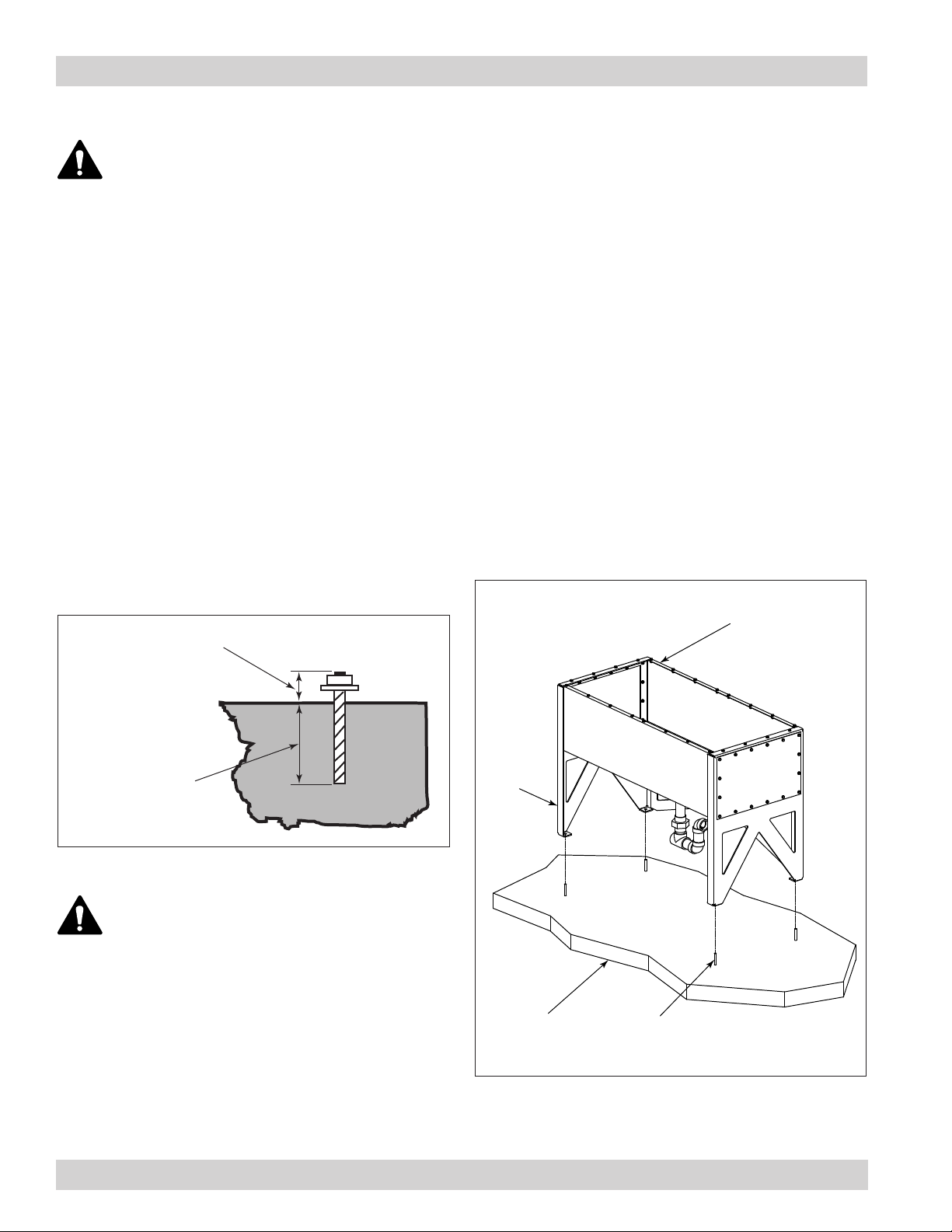
4. Lower the inlet plenum with legs to the anchor bolts.
5. Level inlet plenum and secure all hardware.
6. Apply supplied sealant to the top flange of the inlet
plenum.
inlet plenum
foundation anchor bolt
leg
Inlet Plenum Installation, WSO 25-2 shown
Anchor should project
a minimum of 1 3/4-in
and account for nut,
washer, base plate
and shims/grout.
Embedment depth
Provisional Anchor Bolt Recommendations
1. Consider Hilti HIT-HY 200 Anchor System or
equivalent. Quantity of anchor bolts should match the
number of holes provided in the base plates.
2. Anchor diameter is typically 1/8-in less than
baseplate hole diameter.
3. Corrosive environment or outdoor installation may
require stainless steel anchors.
Anchors must comply with local code
requirements and must be capable of
supporting dead, live, wind, seismic, and other
applicable loads.
Anchor sizes shown are provisional, as final
anchor sizing will depend on jobsite load
conditions, collector location, foundation/
framing design variables and local codes.
Consult a qualified engineer for final selection
of suitable anchors.
Typical Floor Mount Installation
Leg sets for standard collector sizes are shown in the
Rating and Specification Information. Reference Typical
Foundation Anchor and leg assembly drawing shipped
with the collector prior to starting assembly.
1. Prepare the foundation or support framing in the
selected location. Locate and install anchors.
WSO Mist Collector, WSO 20, 25-1, 25-2, and 25-3
10
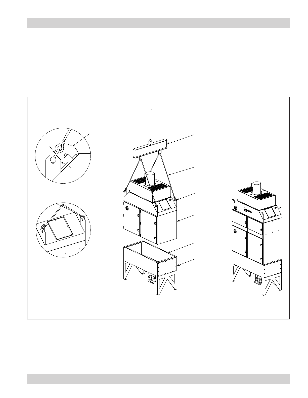
Completed Installation
Filter Cabinet Installation
Lifting Lug Angle
Incorrect Lifting Orientation
(correct lifting orientation
shown to the right)
filter
cabinet
sealant
inlet
plenum
lifting lug
Correct Lifting
Orientation
angle not to exceed
30° from vertical
(minimum 60°
from horizontal)
clevis
pin
lifting
lug
spreader bar
Completed Installation, Powered WSO 25-2 shown
7. Remove the first stage and primary filters from the
filter cabinet and set aside.
8. Using a crane or forklift, raise the filter cabinet
section to the required height. See below illustration
for correct lifting orientation.
9. Set cabinet on top of the inlet plenum flange and
attach with the supplied fasteners.
10. Remove crane or forklift.
11. Re-install the first stage and primary filters.

11
Donaldson Company, Inc.
Ceiling Mount (WSO 20 and 25-1)
Failure to lift the collector correctly can result
in severe personal injury or property damage.
Use appropriate lifting equipment and adopt
all safety precautions needed for moving and
handling the equipment.
A crane or forklift is recommended for
unloading, assembly, and installation of the
collector.
Location must be clear of all obstructions,
such as utility lines or roof overhang.
Ensure weight of oil-laden collector plus
weight of required materials and equipment
will be adequately supported. Failure to comply
may result in personal injury and/or property
damage.
Top View
45°
Front View
60°
Isometric View
customer-supplied
chain or cable
eye bolt
Ceiling Mount Installation, WSO 20 shown
1. Verify that the ceiling attachment points can bear the
live load.
2. Use properly sized cable or chain to attach to each
of the four WSO attachment lugs (WSO 25-1) or
eyebolts (WSO 20) to suspend the collector from the
ceiling.
3. To prevent sway, position the chain or cable to form
a 60 degree angle to the top of the collector and a 45
degree angle along the sides.
WSO Mist Collector, WSO 20, 25-1, 25-2, and 25-3
12
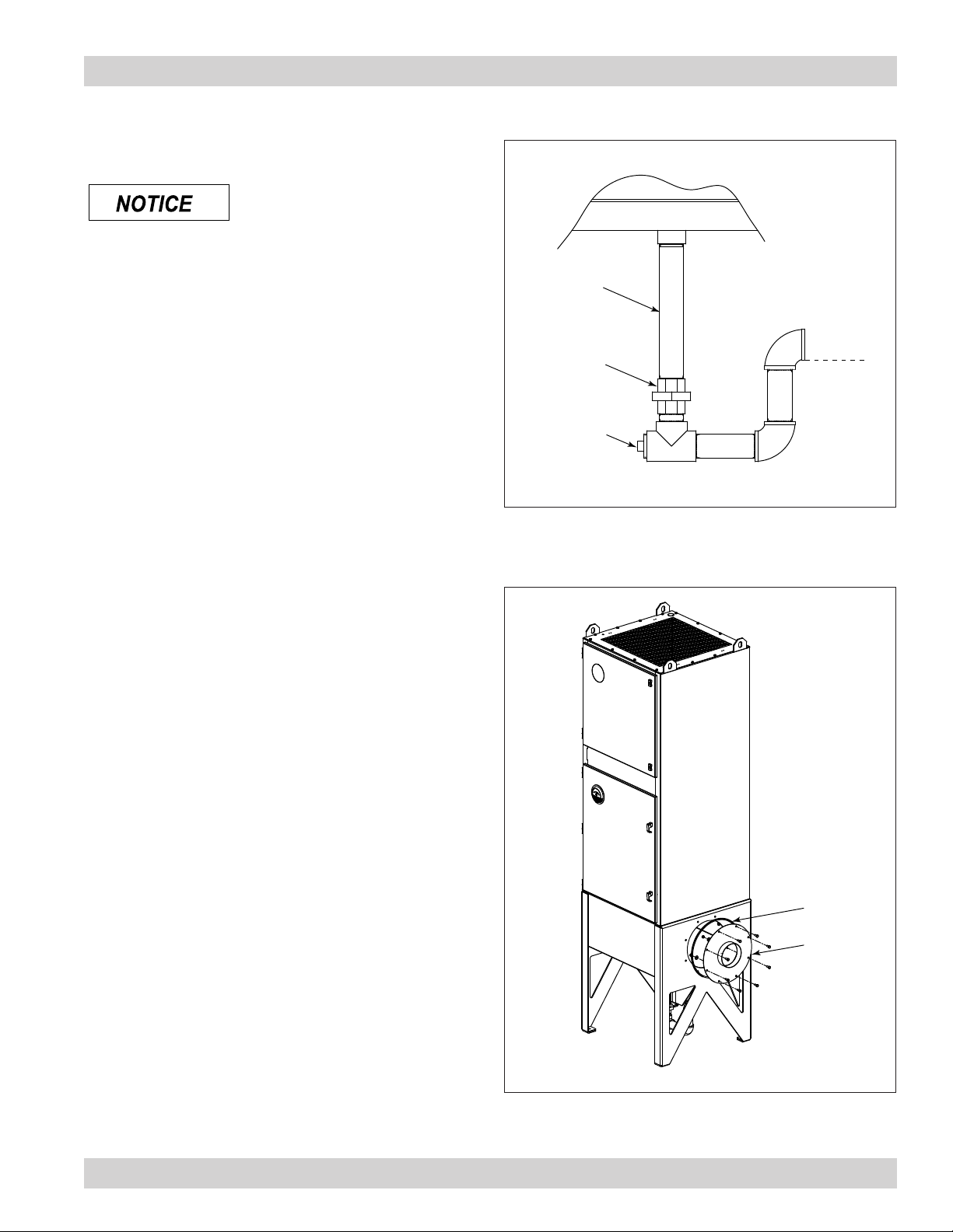
P-Trap Installation
Ensure collected material
properly flows through the
P-Trap. The P-Trap dimensions
should accommodate a column of coolant
greater than the static capacity of the fan
to avoid coolant pooling in the collector and
potentially causing property damage.
1. Install the P-Trap as shown in P-Trap Installation.
2. Position the P-Trap outlet to the proper location and
tighten the union.
3. Plumb the P-Trap to a receptacle or install a return
line back to the machine center.
4. Fill P-Trap before starting collector.
Note: The characteristics of some machining
fluids change with time, use, and exposure
to air. Check the condition of the collected
fluid before re-using.
Inlet Collar Installation
(WSO 20 and 25-1)
1. Install the inlet collar to the desired inlet location
using the supplied sealant and hardware.
2. For single-inlet configurations, install the inlet
blank to the inlet opposite the inlet collar using the
supplied sealant and hardware.
(WSO 25-2 and 25-3)
1. Refer to the Specification Control Drawing to get the
dimensions and bolt pattern of the inlet. Typically,
a rectangle-to-round transition, custom to your
particular installation, is obtained from the ducting
supplier. Install the rectangle-to-round transition to
the desired inlet location using the supplied sealant
and hardware.
2. For single-inlet configurations, install the inlet
blank to the inlet opposite the inlet collar using the
supplied sealant and hardware.
hopper
maximum
fill level
union
pipe plug
NPT pipe
P-Trap Installation
sealant
inlet collar
Inlet Collar Installation, WSO 25-1 shown

13
Donaldson Company, Inc.
Electrical Wiring
Electrical installation, service, or maintenance
work must be performed by a qualified
electrician and comply with all applicable
national and local codes.
This collector may start or stop unexpectedly
from a remote location. Turn power off and lock
out electrical power sources before performing
service or maintenance work.
Do not install in classified hazardous
atmospheres without an enclosure rated for
the application.
All electrical wiring and connections, including electrical
grounding, should be made in accordance with the
National Electric Code (NFPA No. 70-latest edition).
Check local ordinances for additional requirements that
apply.
The appropriate wiring schematic and electrical rating
must be used. See collector’s rating plate for required
voltage.
An electric disconnect switch having adequate amp
capacity shall be installed in accordance with Part IX,
Article 430 of the National Electrical Code (NFPA No.
70-latest edition). Check collector’s rating plate for
voltage and amperage ratings.
Refer to the wiring diagram for the number of wires
required for main power wiring and remote wiring.

WSO Mist Collector, WSO 20, 25-1, 25-2, and 25-3
14
Motor Starter Control Box
Mount the motor starter control box in a convenient
location. For the WSO 20 and 25-1, an electrical
knockout, sized for 1/2-in fittings, is provided on the left-
hand side of the blower cabinet. Increase knockout size
using a drill as required.
1. Using the wiring diagram supplied inside the control
box and the instructions on the motor decal, make
the connections to the blower motor.
Note: If the collector is supplied with an optional
junction box, wire the motor starter to the
terminal strip located inside the junction box
according to the wiring diagram supplied
with the junction box.
Instruct all personnel on safe use and maintenance
procedures.
Electrical work during installation, service or
maintenance must be performed by a qualified
electrician and comply with all applicable
national and local codes.
Turn power off and lock out electrical
power sources before performing service or
maintenance work.
Check that the collector is clear and free of all
debris before starting.
Do not install in classified hazardous
atmospheres without an enclosure rated for
the application.
Optional fans over 600 lbs must be
independently supported.
Preliminary Start-Up Check
2. Check all electrical connections for tightness and
contact.
3. Check for proper rotation as noted on the fan and/
or hopper discharge device housing. Clockwise for
WSO 25-1, powered WSO 25-2 and 25-3 and see
rotation arrow on the motor’s mounting plate for
WSO 20.
To reverse rotation, single-phase power supply:
Follow manufacturer’s instructions on the motor’s
nameplate.
To reverse rotation, three-phase power supply:
Switch any two leads on the motor junction box.
Do not look into fan outlet to determine
rotation. View the fan rotation through the
back of the motor.
Check that the exhaust plenum is free of tools
or debris before checking blower/fan rotation.
Stand clear of exhaust to avoid personal injury.
Do not interchange a power lead with the
ground wire. Severe personal injury and/or
property damage may result.
4. Check that all filters are properly installed.
5. All access panels should be sealed and secure.
6. Check and remove all loose items in or near the inlet
and outlet of the collector.
7. Check that all remote controls are properly wired
and all service switches are in the OFF position.
8. Check that all optional accessories are installed
properly and secured.
9. Fill P-Trap if equipped, or close faucet valve on drain
collection container if used.
10. Turn blower fan motor ON.

15
Donaldson Company, Inc.
6. If equipped with a HEPA or 95% DOP, monitor
pressure drop across after filter. Initial final filter
pressure drop is approximately 1-2”wg. Replace the
final filter when the gauge reads 3.5 to 4.0”wg. Do
not attempt to clean or wash the final filter. Replace
only.
Do not operate the collector
without the first- or primary-
stage filter in place. Significant reduction in
final filter life can result.
Instruct all personnel on safe use and maintenance
procedures.
Use proper equipment and adopt all safety
precautions needed for servicing equipment.
Use appropriate access equipment and
procedures. Note the standard collector is not
equipped with access platforms unless noted
on the specification drawings.
Electrical service or maintenance work must
be performed by a qualified electrician and
comply with all applicable national and local
codes.
Turn power off and lock out electrical
power sources before performing service or
maintenance work.
Do not install in classified hazardous
atmospheres without an enclosure rated for
the application.
Maintenance Information
Operational Checklist
1. Monitor the physical condition of the collector and
repair or replace any damaged components.
Routine inspections will minimize downtime and
maintain optimum system performance. This
is particularly important on continuous-duty
applications.
2. Monitor pressure drop across filters.
Abnormal changes in pressure drop may indicate a
change in operating conditions and possibly a fault
to be corrected.
3. Monitor exhaust.
4. Monitor hopper drainage. If slow or stopped, check
hopper for obstructions and clean as necessary.
5. Check that the P-Trap is full. Refill if low or dry.
First Stage Filter Cleaning and Installation
Remove the first stage filter through the lower access
door. Clean the first-stage screen by tapping it gently
over an appropriate waste container. If further cleaning
is required, wash in an appropriate wash tank. To clean
the first-stage filter, soak in an appropriate wash tank,
rinse, dry, and re-install.
High temperature, steam-
cleaning methods should not be
used with the polypropylene filters due to the
temperature limitations.
Do not operate the WSO mist collector without
the first-stage filter in place. Significant
reduction in primary filter life can result.
Use proper safety and protective equipment
when removing contaminants and filters.
Dirty filters may be heavier than they appear.
Use care when removing filters to avoid
personal injury and/or property damage.
Turn power off and lock out electrical
power sources before performing service or
maintenance work.
Do not operate with missing or damaged filters.
Filter Removal and Installation

WSO Mist Collector, WSO 20, 25-1, 25-2, and 25-3
16
Primary Filter Installation
Note: With the collector’s airflow off, allow mist-
laden, wet filter to drain into the inlet plenum
for at least 15 minutes prior to removal.
1. Remove the filter cartridge by pulling the filter
retention lever down to a horizontal position. Remove
cartridge from collector and dispose of properly for
the materials collected.
Note: A large plastic garbage bag placed over the
top of the used filter allows cleaner filter
change out. The filter can be tipped forward
and out of the collector while the bag is
pulled up over the bottom of the cartridge.
2. Place new filter on the filter retention platform,
gasket side up. Slide filter back as far as it will go.
Note: The primary filter must be replaced. Do not
wash.
3. Lift the filter retention lever up and close access
door.
primary
filter cartridge
filter retention lever
pull down
Primary Filter Replacement, WSO 25-1 shown

17
Donaldson Company, Inc.
Final Filter Installation (WSO 20 and 25-1)
Note: The final filter must be replaced. Do not
wash.
1. Unlatch the final filter on top of the collector.
2. Remove the filter and dispose of properly for the
materials collected.
Dirty filters may be heavier than
they appear. Provide a support
platform or have two people, one on each side
of the filter and pull the filter out.
3. Install the replacement filter gasket-side down.
4. Latch the new filter in place.
Final Filter Installation (WSO 25-2 and 25-3)
Note: The final filter must be replaced. Do not
wash.
1. Open the final filter access door and lower the
retention handles to release the filter.
2. Remove the filter and dispose of properly for the
materials collected.
Dirty filters may be heavier than
they appear. Provide a support
platform or have two people, one on each side
of the filter and pull the filter out.
3. Install the replacement filter gasket-side up.
4. Seal the filter in place by lifting the retention handles
to the upright position.
final filter
(gasket-side
down)
latch
Final Filter Installation, WSO 25-1 shown
final filter
(gasket-side up)
retention
handle
Final Filter Installation, Powered WSO 25-2 shown
This manual suits for next models
3
Table of contents
Popular Fan manuals by other brands


Craftmade
Craftmade PU52OB5 installation guide

Monte Carlo Fan Company
Monte Carlo Fan Company 5HLR54 Series Owner's guide and installation manual

NScessity
NScessity NSMTF-18 instruction manual

Vents
Vents CF user manual

minkaAire
minkaAire aluma wet instruction manual

Vent-Axia
Vent-Axia Centrif Duo Installation and wiring instructions


