Tormach PATHPILOT OPERATOR CONSOLE User manual

TECHNICAL DOCUMENT Version 0420A
INSTALLATION GUIDE
PATHPILOT OPERATOR CONSOLE ASSEMBLY
FOR 770M/770M+/770MX
Page 1

1.1 PURPOSE
This document gives instructions on installing the PathPilot Operator
Console Assembly for 770M/770M+/770MX.
1.2 PRODUCT INFORMATION
Product: PathPilotOperator Console Assembly for
770M/770M+/770MX (PN50441)
Quantity Description
1 Controller Enclosure Mount (PN 39308)
1 Controller Wire Kit (PN50367)
1 Jog Pendant (PN50363)
1 Machine Controller
Note: If any items are missing, we can help. Email
support@tormach.com to contact Tormach Technical
Support for guidance on how to proceed.
1.3 REQUIRED TOOLS
This procedure requires the following tools. Collect them before you
begin.
l15/64 in. drill bit
lElectric drill
lHole punch
lLevel
lMetric hex wrench set
lPhillips screwdriver
lPhillips screwdriver, small
lScissors
lTape
1.4 BEFORE YOU BEGIN
lMachine Arm Not Compatible If you already have a
machine arm installed on your machine, you must first
disassemble it. Refer to the product's documentation, and
follow the steps in reverse order.
lMachine Enclosure Required If you haven't yet done so,
you must first install the machine's enclosure. See the
product's documentation for more information.
Page 2
©Tormach® 2020
Specifications subject to change without notice.
tormach.com
TD10715: Installation Guide: PathPilot Operator Console for 770 (0420A)
TECHNICAL DOCUMENT

2.1 PREPARE THE MACHINE
1. Power off the machine and the PathPilot controller.
a. Push in the Emergency Stop button on the operator box,
which removes power to motion control.
b. From the PathPilot interface, select Exit.
c. Turn the Main Disconnect switch to OFF on the side of the
electrical cabinet.
2. Close the enclosure doors.
NOTICE! This procedure requires you to drill four holes
into the enclosure. If the enclosure's right door is open,
there's a risk that you'll drill into it.
2.1.1 Remove the Right Side Window
To make it easier to install the mount arm, we recommend
removing the right side window from the enclosure. Loosen
the screws on the vertical window retainers, and slide the
window out of the right side panel. Set the window aside.
2.1.2 Remove the Operator Box
1. Remove the Emergency Stop cable from the operator box.
2. Remove the four screws that secure the operator box to the
machine stand using a 3 mm hex wrench.
Discard the operator box.
3. Put the four screws from the operator box back on to the
machine stand.
2.2 INSTALL THE MOUNT ARM
1. Find the drill template (provided), and cut it out along its
edges.
2. Find the operator console's mount arm.
3. Put the drill template on the mount arm's top bracket. Then,
verify that the holes on the bracket align with the holes on the
drill template. If they don't, trace the correct hole pattern on
to the drill template.
4. Align the drill template to the top of the enclosure and tape it
in place, as shown in the following image.
Figure 2-1: Drill template taped to the enclosure.
5. Put a mark in each hole on the drill template using a hole
punch.
6. Remove the drill template from the enclosure and discard it.
7. Drill into the marks on the enclosure that you made in Step 5
using an electric drill and a 15/64 in. drill bit.
Figure 2-2: Drilling holes into the top of the enclosure.
8. Secure the top of the mount arm to the enclosure with four
M6 screws, four washers, and four nuts using an M3 hex
wrench.
Figure 2-3: Securing the top of the mount arm to the
enclosure.
Page 3
©Tormach® 2020
Specifications subject to change without notice.
tormach.com
TD10715: Installation Guide: PathPilot Operator Console for 770 (0420A)
TECHNICAL DOCUMENT

9. Using a level, align the bottom of the mount arm with the
bottom of the enclosure.
Figure 2-4: Bottom of the mount arm level on the
enclosure.
10. Using the bottom of the mount arm as a template, drill one
hole using an electric drill and a 15/64 in. drill bit.
11. Put one M6 screw, one washer, and one nut into the hole that
you drilled in Step 10 using an M3 hex wrench.
The mount arm is now secure enough to reliably drill the
remaining three holes.
12. Drill the remaining three holes for the mount arm's bottom
bracket.
Figure 2-5: Drilling the remaining three holes into the
enclosure.
13. Put three M6 screws, three washers, and three nuts into the
remaining three holes using an M3 hex wrench.
14. Once the mount arm is secured to the enclosure, open the
enclosure door and verify that the mount arm's screws don't
interfere with the enclosure door jamb. If they do, loosen the
screws on the door jamb, and slide it toward the back of the
machine.
Figure 2-6: Door jamb moved to provide clearance for the
mount arm's screws.
2.3 MOUNT THE CONSOLE
Complete the following steps in the order listed:
2.3.1 Assemble the Controller and Keyboard Tray 4
2.3.2 Lift and Secure the Controller Assembly 5
2.3.1 Assemble the Controller and Keyboard Tray
1. Find the three provided split collars. If they're connected,
remove their bolts using a 6 mm hex wrench, and separate
them. The split collars are matched pairs, so you must keep
them together.
Figure 2-7: One split collar disassembled.
2. Find the four provided pieces of plastic with adhesive backing.
Cut each piece of plastic so that it's the length of the inside of
the split collar.
Page 4
©Tormach® 2020
Specifications subject to change without notice.
tormach.com
TD10715: Installation Guide: PathPilot Operator Console for 770 (0420A)
TECHNICAL DOCUMENT

3. Adhere one piece of plastic to the inside of each split collar.
Figure 2-8: Adhering tape on the inside of a split collar.
4. Find the three provided mount arm brackets.
Figure 2-9: Mount arm brackets.
5. Loosely attach two of the mount arm brackets to the left side
of the controller with four M4 screws using a 2.5 mm hex
wrench, as shown in the following image. Verify that the
curved edge is facing away from the controller.
Note: Don't completely tighten the brackets to the
controller. You'll adjust them when you're adjusting
the height of the entire console assembly.
Figure 2-10: Two mount brackets attached to the
controller.
6. Attach one side of two split collars to the mount arm brackets
with four M6 screws and four washers using a 3 mm hex
wrench.
Figure 2-11: Split collars attached to the mount arm
brackets on the controller.
7. Find the keyboard tray provided. Then, attach the remaining
mount arm bracket to the left side of the keyboard tray with
two M4 screws using a 2.5 mm hex wrench. Verify that the
curved edge is facing away from the keyboard tray.
8. Attach one side of one split collar to the mount arm bracket
with two M6 screws, two washers, and two nuts using a 3
mm hex wrench.
Figure 2-12: Split collar attached to the mount arm bracket
on the keyboard tray.
9. Find the provided jog pendant bracket. Then, attach it to the
left side of the controller (between the two mount arm
brackets) with two M4 screws using a 2.5 mm hex wrench.
10. Set the keyboard tray aside.
2.3.2 Lift and Secure the Controller Assembly
1. Attach the remaining split collar to the mount arm, and
completely tighten it using a 6 mm hex wrench. This split
collar determines the height for the overall console assembly,
Page 5
©Tormach® 2020
Specifications subject to change without notice.
tormach.com
TD10715: Installation Guide: PathPilot Operator Console for 770 (0420A)
TECHNICAL DOCUMENT

so we suggest attaching it 16 in. from the top of the
enclosure.
Figure 2-13: Split collar attached to the mount arm.
CAUTION! Team Lift Required:You must have the
aid of more than one person to lift and move the
object. The object is heavy, and lifting it by yourself
can cause serious injury.
2. Lift the console and hold it on the right side of the mount arm.
3. Align the bottom split collar on the controller with the split
collar that you installed on the mount arm in Step 1.
4. With the aid of another person, loosely attach the opposite
side of both split collars to the mount arm using a 6 mm hex
wrench.
Figure 2-14: Loosely attaching the split collars to the mount
arm.
5. Find the keyboard tray that you set aside earlier. Then, attach
it to the bottom of the controller, as shown in the following
image.
Figure 2-15: Attaching the keyboard tray to the bottom of
the controller.
6. Loosely attach the opposite side of the split collar to the
mounting arm using a 6 mm hex wrench.
7. Adjust the height and the angle of the console assembly as
required.
8. Securely tighten all four split collars using a 6 mm hex
wrench. Securely tighten all mount arm brackets using a 2.5
mm hex wrench.
2.4 MAKE ELECTRICAL CONNECTIONS
1. Find the provided Jog Pendant (PN50363).
2. Hang the jog pendant on its bracket (on the front of the
controller) as shown in the following image.
Figure 2-16: Jog pendant on the front of the console
assembly.
3. Route the loose end of the jog pendant to the back of the
controller.
4. Find the provided power supply bracket. Then, attach it to the
back of the controller with two M3 screws using a 2.5 mm hex
wrench.
Page 6
©Tormach® 2020
Specifications subject to change without notice.
tormach.com
TD10715: Installation Guide: PathPilot Operator Console for 770 (0420A)
TECHNICAL DOCUMENT

5. Find the provided power, Ethernet, emergency stop extension,
and ATCUSB cables, and the WiFi dongle. Then, connect them
– and the jog pendant cable – to the controller as shown in
the following image.
Figure 2-17: Controller connections.
6. Put the power supply into the power supply bracket.
7. Find the provided corrugated tubing and piece of rubber.
8. Attach the piece of rubber to the bracket on the rear of the
keyboard tray as shown in the following image.
Figure 2-18: Rubber attached to the bracket on the
keyboard tray.
9. Put the loose ends of all cables from the controller into the
corrugated tubing.
10. Push the corrugated tubing into the bracket on the rear of the
keyboard tray.
Figure 2-19: Cords put into corrugated tubing, which is
attached to the rear of the keyboard tray.
11. Find the access panel on the machine stand as shown in the
following image.
Figure 2-20: Access panel on the machine stand.
12. Remove the access panel using a 2 mm hex wrench, and
discard the panel. Set the screws aside for later in this
procedure.
13. Find the provided access panel. Then, put the loose end of the
corrugated tubing and all cords through it as shown in the
following image.
Figure 2-21: Loose end of corrugated tubing and all cords
put through the access panel.
Page 7
©Tormach® 2020
Specifications subject to change without notice.
tormach.com
TD10715: Installation Guide: PathPilot Operator Console for 770 (0420A)
TECHNICAL DOCUMENT

14. Attach the access panel – with the corrugated tubing and all
cords – to the machine stand with the screws that you set
aside in Step 12 using a 2 mm hex wrench.
Figure 2-22: Access panel attached to the machine stand.
15. Route the loose end of all cords through the machine stand
and out toward the rear of the machine.
16. Connect the operator box extension cable to the existing
operator box cable (preinstalled on the machine).
17. Connect the Ethernet cable to the Controller Communications
port on the side of the electrical cabinet.
18. From the ATC, remove and discard the existing USB cable.
Then, route the loose end of the ATCUSB cable from the
controller to the ATC, and connect it in place of the original
USB cable.
19. If you have an EU model of the PathPilot Operator Console
Assembly for 770M/770M+/770MX, find the provided set of
keys, and put it into the top of the controller.
Figure 2-23: Key put into the controller.
For more information on operation modes, refer to the EU
machine operator's manual.
2.5 REASSEMBLE THE MACHINE
1. Put the right side window (that you set aside in "Prepare the
Machine" (page3)) back into the right side panel on the
enclosure. Then, tighten the screws on the vertical window
retainers
2. Power on the machine and the PathPilot controller.
a. Turn the Main Disconnect switch to ONon the side of the
electrical cabinet.
b. Twist out the Emergency Stop button on the operator box,
which enables movement to the machine axes and the
spindle.
c. Press the Reset button on the operator box.
d. Bring the machine out of reset and reference it.
Page 8
©Tormach® 2020
Specifications subject to change without notice.
tormach.com
TD10715: Installation Guide: PathPilot Operator Console for 770 (0420A)
TECHNICAL DOCUMENT

TECHNICAL DOCUMENT
2.6 TROUBLESHOOTING
Problem
The touch screen does not respond to touch inputs on all or part of the screen's surface.
Cause
The sensitivity setting for the touch controller is too low.
Solutions
You Might
Need To... Probability How-To Steps Need More?
Adjust
touchscreen
sensitivity.
High 1. Verify that you have PathPilot v2.4.4 or higher
installed on your console.
2. From the PathPilot interface, in the MDI Line
DRO field, type
ADMINTOUCHSCREENSENSITIVITY 1000
and press Enter. You can use a value between 1
and 2047, but 1000 is generally sufficient for
most shop spaces.
The touchscreen used in the operator console is a resistive
type, to prevent accidental triggering from drops of coolant
on the screen. The resistive touchscreen may need its
sensitivity adjusted when used in a shop space with very high
or low humidity.
Page 9
©Tormach® 2020
Specifications subject to change without notice.
tormach.com
TD10715: Installation Guide: PathPilot Operator Console for 770 (0420A)

TECHNICAL DOCUMENT
Problem
The console screen doesn't display an image or respond to the power button.
Cause
The console isn't receiving power.
Solutions
You Might
Need To... Probability How-To Steps Need More?
Examine power
input to the
console.
High Examine the green LED on the power brick
for the console. If it's not lit, examine the
power cords to the power brick.
If your console receives power from the Accessory Input ports
on the machine, look for tripped breakers inside your
machine's electrical cabinet.
Test the power
button
functionality.
Low Examine the green ring around the power
button. It should light up when you press
the power button.
Page 10
©Tormach® 2020
Specifications subject to change without notice.
tormach.com
TD10715: Installation Guide: PathPilot Operator Console for 770 (0420A)

TECHNICAL DOCUMENT
Problem
The console screen turns on, but is scrambled or illegible.
Cause
The BIOS isn't configured for the correct screen output.
Solutions
You Might Need To... Probability How-To Steps Need More?
Configure the display
output settings in BIOS.
High 1. Connect a VGA monitor to the
console
2. Power the console on and select
the Delete key to enter the BIOS.
3. From the Advanced tab, select
Display Configuration.
4. Configure the display as follows:
lPrimary IGFX Boot
Display:Auto
lLCD Panel Type: 1280x1024
LVDS
lPanel Channel:Dual Channel
lPanel Color Depth: 24 Bit
5. Select the Esc key, go to Save and
Exit, and select Save Changes and
Reset.
This configuration problem can occur if your console has a
CMOS battery failure. Replace the battery if it reoccurs.
Page 11
©Tormach® 2020
Specifications subject to change without notice.
tormach.com
TD10715: Installation Guide: PathPilot Operator Console for 770 (0420A)

TECHNICAL DOCUMENT
Problem
The RPM, Feed Override, or Max Velocity knobs don't respond or aren't smooth.
Cause
The ribbon cable connecting the knobs is disconnected or the circuit board is damaged.
Solutions
You Might Need
To... Probability How-To Steps Need More?
Examine the
connectors on
the ribbon cable.
High 1. Remove the rear panel of the
console.
2. Examine the connectors on both
ends of the cable going from J4
on the control board to the
potentiometer board.
Shipping can sometime cause connectors to become loose. Re-seating
the connectors will usually fix non-responsive override knobs.
Examine the USB
connection to the
control board.
High 1. Remove the rear panel of the
console.
2. Examine the USB cable going
from the header on the computer
motherboard to connector J12 on
the control board.
Verify that the power LED on the console control board lights up when
the console is turned on. If it doesn't light up, and you have confirmed
the USB connection, replace the control board (PN 39146).
Page 12
©Tormach® 2020
Specifications subject to change without notice.
tormach.com
TD10715: Installation Guide: PathPilot Operator Console for 770 (0420A)
TECHNICAL DOCUMENT
Problem
The Cycle Start or Feed Hold buttons don't respond.
Cause
The control board is disconnected or the wires to the buttons are loose.
Solutions
You Might
Need To... Probability How-To Steps Need More?
Examine the
wiring to the
buttons.
High 1. Remove the rear panel of the console.
2. Examine the wire inputs to connector J13 on the
control board. If any wires are loose, tighten the
screw terminals.
3. Using a continuity tester, measure the resistance
between terminals 1 and 2 when Feed Hold is
pressed and 3 and 4 when Cycle Start is pressed.
lIf there's continuity at the terminals on the
control board and the buttons still don't
work, examine the USB cable to the
control board.
lIf there's not continuity at the terminals
when the buttons are pressed, remove the
lower rear panel of the console and
examine the screw terminals on the rear
of the buttons themselves.
Shipping can sometime cause wire terminals to become
loose. Re-seating the wires will usually fix non-responsive
buttons.
If you have tested all terminals and the buttons still don't
have continuity when pressed, replace the buttons:
lFeed Hold Button (PN 37363)
lCycle Start Button (PN37362)
Examine the
USB
connection to
the control
board.
High 1. Remove the rear panel of the console.
2. Examine the USB cable going from the header
on the computer motherboard to connector J12
on the control board.
Verify that the power LED on the console control board
lights up when the console is turned on. If it doesn't light
up and you have confirmed the USB connection, replace
the control board (PN 39146).
Page 13
©Tormach® 2020
Specifications subject to change without notice.
tormach.com
TD10715: Installation Guide: PathPilot Operator Console for 770 (0420A)
REVISION
LOCATION:
Document realized with version :
CONTRACT:
SC EME
C ANGESNAMEREV. DATE
1 2 3 4 5 6 7 8 9 10
02
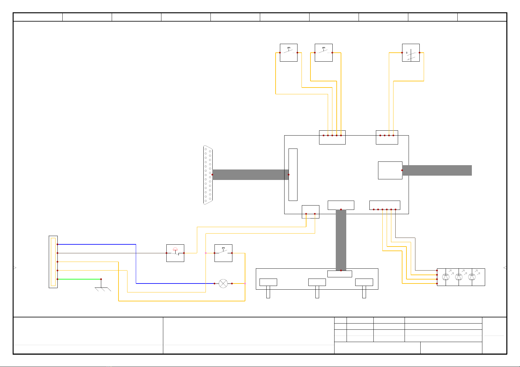
+L1 Electrical Panel
Machine Schematic
0
2018.0.2.14
Tormach, Inc
1071 Uniek Dr.
Waunakee, WI 53597
User data 1 User data 2
0 2/20/2019 pdenhartog
SOLIDWORKS Electrical
-S2
5
6
3
4
-S2
Reset
37342
-S1
1
2
Emergency Stop
30462
-X1
1
2
3
4
5
402
404
GND1
401
403
-X2
39379
3
4
-S3
Cycle Start
37362
3
4
-S4
Feedhold
37363
PN 39376
Override Knobs
-LED1
5v
G
R
B
J13 J14
J11 J2
J3 J12
E-Stop Passthrough
RGB LED
2R KeySwFront Panel Buttonas
Jog Pendant
USB
J4
Override Knobs
39146
Control Board
5v
G
R
B
F
GND
CS
GND
KEY
GND
2R
GND
-S5
Key Switch

Drill Four
6 mm Holes Keep edge flush
with top of
enclosure
770M/M+/MX PathPilot Operator Console Drill Template
To download/print this template, go to tormach.com/docs
Keep edge flush
with right side
of enclosure
1” Scale Block
This manual suits for next models
1
Table of contents
Other Tormach Music Mixer manuals


