Tormach pathpilot User manual

Page 1
Specifications subject to change without notice.
©Tormach® 2022
TECHNICAL DOCUMENT Version 0822A
INSTALLATION GUIDE
PATHPILOT OPERATOR CONSOLE ASSEMBLY
FOR 770M/770M+/770MX

PURPOSE
LOOKING FOR A VIDEO?
Before you begin, select the image below to watch a walk-through video of this entire installation
procedure.
PURPOSE
This document gives instructions on installing the PathPilot Operator Console Assembly for 770M/770M+/770MX.
PRODUCT INFORMATION
Product: PathPilotOperator Console Assembly for 770M/770M+/770MX (PN50441)
Quantity Description
1 Access Panel
1 Controller Wire Kit (PN50367)
1 Jog Pendant (PN50363)
1 Keyboard Tray
1 Machine Controller
1 Mount Arm
4 Mount Arm Brackets
5 Plastic with Adhesive Backing
18 Screw with Washer, M5 × 0.8 - 10
10 Screw with Washer, M4 × 0.7 - 10
4 Split Collar
Note: If any items are missing, we can help. Create a support ticket with Tormach Technical Support at
tormach.atlassian.net/servicedesk for guidance on how to proceed.
REQUIRED TOOLS
This procedure requires the following tools. Collect them before you begin.
l15/64 in. drill bit
lElectric drill
Page 2
©Tormach® 2022
Specifications subject to change without notice.
tormach.com
TD10715: Installation Guide: PathPilot Operator Console for 770 (0822A)

BEFORE YOU BEGIN
lHole punch
lLevel
lMetric hex wrench set
lPhillips screwdriver
lPhillips screwdriver, small
lScissors
lRuler
lTape
BEFORE YOU BEGIN
lMachine Arm Not Compatible If you already have a machine arm installed on your machine, you must
first disassemble it. Refer to the product's documentation, and follow the steps in reverse order.
lMachine Enclosure Required If you haven't yet done so, you must first install the machine's enclosure.
See the product's documentation for more information.
Page 3
©Tormach® 2022
Specifications subject to change without notice.
tormach.com
TD10715: Installation Guide: PathPilot Operator Console for 770 (0822A)

PREPARE THE MACHINE
PREPARE THE MACHINE
1. Power off the machine and the PathPilot controller.
a. Push in the machine's red Emergency Stop button, which removes power to motion control.
b. From the PathPilot interface, select Exit.
c. Turn the Main Disconnect switch to OFF on the side of the electrical cabinet.
2. Close the enclosure doors.
NOTICE! This procedure requires you to drill four holes into the enclosure. If the enclosure's right door is
open, there's a risk that you'll drill into it.
Remove the Right Side Window
To make it easier to install the mount arm, we recommend removing the right side window from the
enclosure. Loosen the screws on the vertical window retainers, and slide the window out of the right side
panel. Set the window aside.
Remove the Operator Box
1. Remove the Emergency Stop cable from the operator box.
2. Remove the four screws that secure the operator box to the machine stand using a 3 mm hex wrench.
Discard the operator box.
3. Put the four screws from the operator box back on to the machine stand.
INSTALL THE MOUNT ARM
1. Print the drill template provided in this document. To verify that the template printed at the correct size, use
a ruler to measure the 1 in. scale on the template. If the template is incorrectly sized, adjust your printer
settings and try again.
2. Cut out the drill template along its edges.
3. Find the operator console's mount arm.
4. Put the drill template on the mount arm's top bracket. Then, verify that the holes on the bracket align with
the holes on the drill template. If they don't, trace the correct hole pattern on to the drill template.
Page 4
©Tormach® 2022
Specifications subject to change without notice.
tormach.com
TD10715: Installation Guide: PathPilot Operator Console for 770 (0822A)
INSTALL THE MOUNT ARM
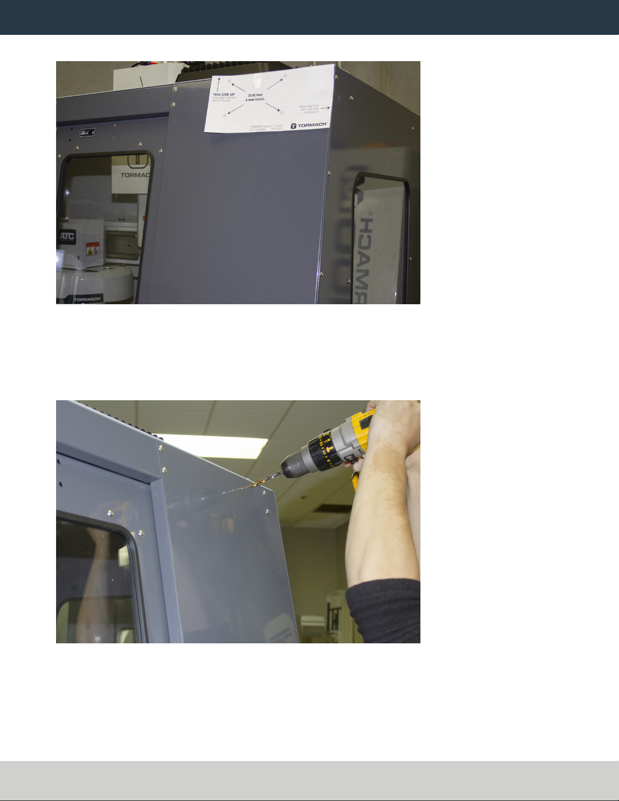
5. Align the drill template to the top of the enclosure and tape it in place, as shown in the following image.
Figure 1: Drill template taped to the enclosure.
6. Put a mark in each hole on the drill template using a hole punch.
7. Remove the drill template from the enclosure and discard it.
8. Drill into the marks on the enclosure that you made in Step 6 using an electric drill and a 15/64 in. (6 mm)
drill bit.
Figure 2: Drilling holes into the top of the enclosure.
Page 5
©Tormach® 2022
Specifications subject to change without notice.
tormach.com
TD10715: Installation Guide: PathPilot Operator Console for 770 (0822A)

INSTALL THE MOUNT ARM
9. Loosely secure the top of the mount arm to the enclosure with four M5 × 0.8 - 10 screws and washers.
Figure 3: Securing the top of the mount arm to the enclosure.
10. Using a level, align the bottom of the mount arm with the bottom of the enclosure.
Figure 4: Bottom of the mount arm level on the enclosure.
11. Using the bottom of the mount arm as a template, drill one hole using an electric drill and a 15/64 in. drill
bit.
12. Put one M5 × 0.8 - 10 screw and washer into the hole that you drilled in Step 11.
The mount arm is now secure enough to reliably drill the remaining three holes.
Page 6
©Tormach® 2022
Specifications subject to change without notice.
tormach.com
TD10715: Installation Guide: PathPilot Operator Console for 770 (0822A)

MOUNT THE CONSOLE
13. Drill the remaining three holes for the mount arm's bottom bracket.
Figure 5: Drilling the remaining three holes into the enclosure.
14. Put three M5 × 0.8 - 10 screws and washers into the remaining three holes.
15. Once the mount arm is secured to the enclosure, open the enclosure door and verify that the mount arm's
screws don't interfere with the enclosure door jamb. If they do, loosen the screws on the door jamb, and
slide it toward the back of the machine.
Figure 6: Door jamb moved to provide clearance for the mount arm's screws.
MOUNT THE CONSOLE
Complete the following steps in the order listed:
Assemble the Controller and Keyboard Tray 8
Lift and Secure the Controller Assembly 11
Page 7
©Tormach® 2022
Specifications subject to change without notice.
tormach.com
TD10715: Installation Guide: PathPilot Operator Console for 770 (0822A)
MOUNT THE CONSOLE
Assemble the Controller and Keyboard Tray
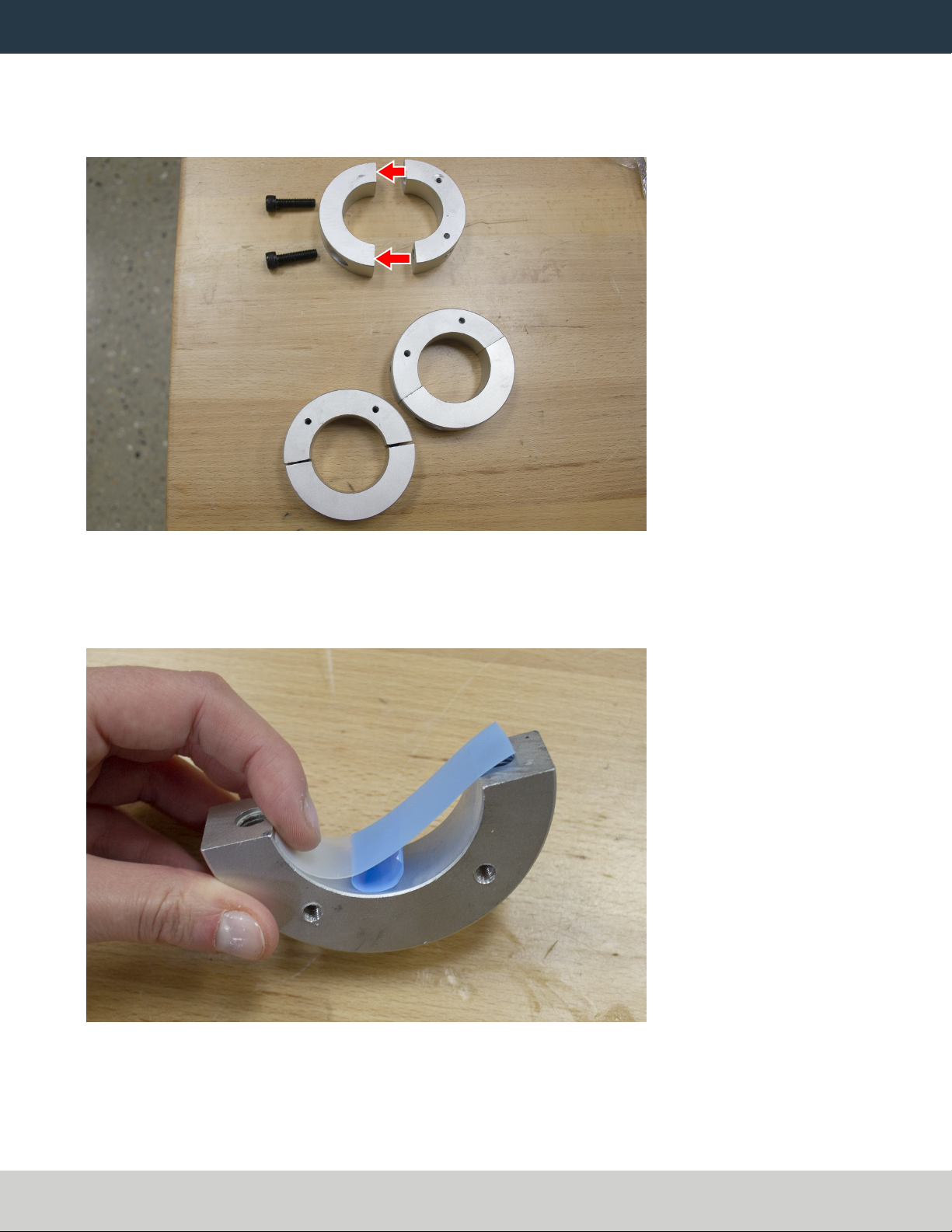
1. Find the three provided split collars. If they're connected, remove their bolts using a 8 mm hex wrench, and
separate them. The split collars are matched pairs, so you must keep them together.
Figure 7: One split collar disassembled.
2. Find the four provided pieces of plastic with adhesive backing. Cut each piece of plastic so that it's the length
of the inside of the split collar.
3. Adhere one piece of plastic to the inside of each split collar.
Figure 8: Adhering tape on the inside of a split collar.
4. Remove the operator console out of its packaging.
Page 8
©Tormach® 2022
Specifications subject to change without notice.
tormach.com
TD10715: Installation Guide: PathPilot Operator Console for 770 (0822A)

MOUNT THE CONSOLE
5. Find the three provided mount arm brackets.
Figure 9: Mount arm brackets.
6. Loosely attach two of the mount arm brackets to the left side of the controller with four M4 × 0.7 - 10
screws using a 2.5 mm hex wrench, as shown in the following image. Verify that the curved edge is facing
away from the controller.
Note: Don't completely tighten the brackets to the controller. You'll adjust them when you're
adjusting the height of the entire console assembly.
Figure 10: Two mount brackets attached to the controller.
Page 9
©Tormach® 2022
Specifications subject to change without notice.
tormach.com
TD10715: Installation Guide: PathPilot Operator Console for 770 (0822A)

MOUNT THE CONSOLE
7. Attach the threaded side of two split collars to the mount arm brackets with four M5 × 0.8 - 10 screws and
washers.
Figure 11: Split collars attached to the mount arm brackets on the controller.
8. Find the keyboard tray provided. Then, attach the remaining mount arm bracket to the left side of the
keyboard tray with two M4 × 0.7 - 10 screws using a 2.5 mm hex wrench. Verify that the curved edge is
facing away from the keyboard tray.
9. Attach one side of one split collar to the mount arm bracket with two M5 × 0.8 - 10 screws and washers.
Figure 12: Split collar attached to the mount arm bracket on the keyboard tray.
10. Find the provided jog pendant bracket. Then, attach it to the left side of the controller (between the two
mount arm brackets) with two M4 × 0.7 - 10 screws using a 2.5 mm hex wrench.
Page 10
©Tormach® 2022
Specifications subject to change without notice.
tormach.com
TD10715: Installation Guide: PathPilot Operator Console for 770 (0822A)
MOUNT THE CONSOLE
11. Set the keyboard tray aside.
Lift and Secure the Controller Assembly
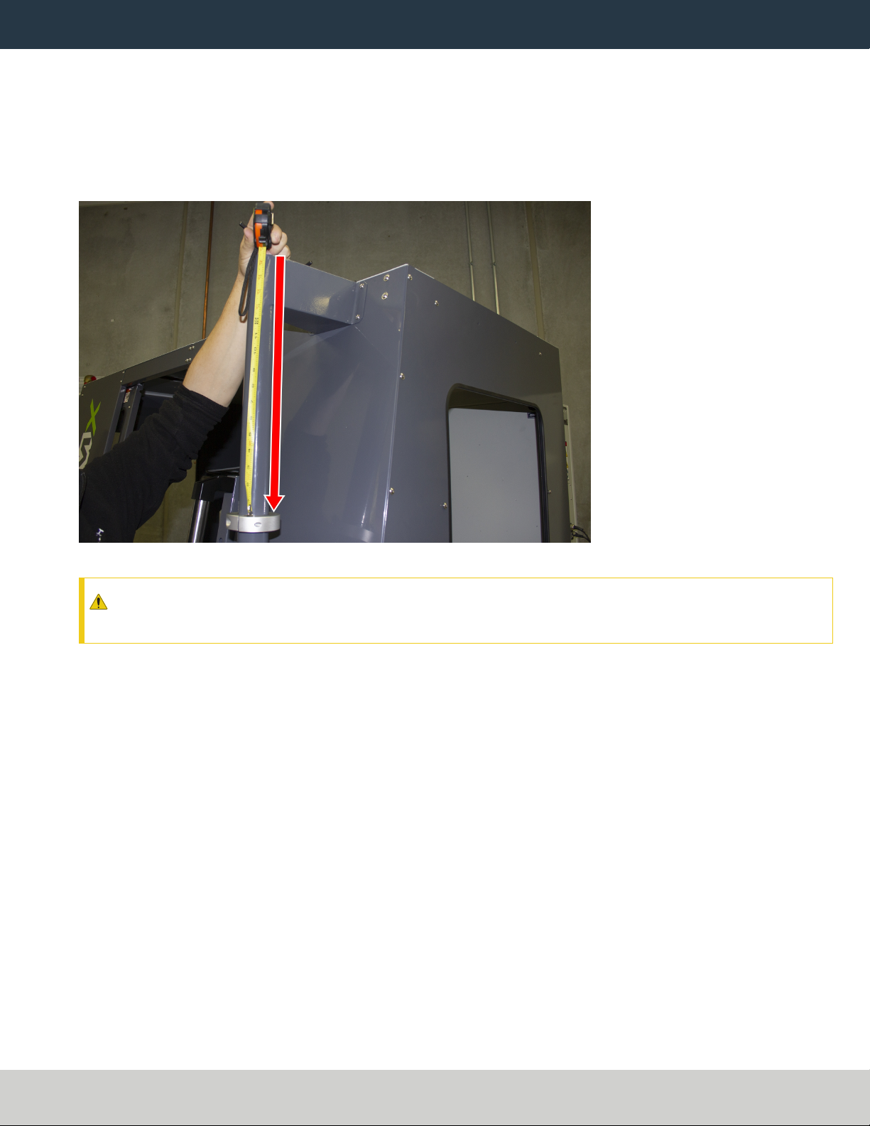
1. Attach the remaining split collar to the mount arm, and completely tighten it using a 8 mm hex wrench. This
split collar determines the height for the overall console assembly, so we suggest attaching it 16 in. (41 cm)
from the top of the enclosure.
Figure 13: Split collar attached to the mount arm.
CAUTION! Team Lift Required:You must have the aid of more than one person to lift and move the
object. The object is heavy, and lifting it by yourself can cause serious injury.
2. Lift the console and hold it on the right side of the mount arm.
3. Align the bottom split collar on the controller with the split collar that you installed on the mount arm in
Step 1.
Page 11
©Tormach® 2022
Specifications subject to change without notice.
tormach.com
TD10715: Installation Guide: PathPilot Operator Console for 770 (0822A)
MOUNT THE CONSOLE
4. With the aid of another person, loosely attach the opposite side of both split collars to the mount arm using
a 8 mm hex wrench.
Figure 14: Loosely attaching the split collars to the mount arm.
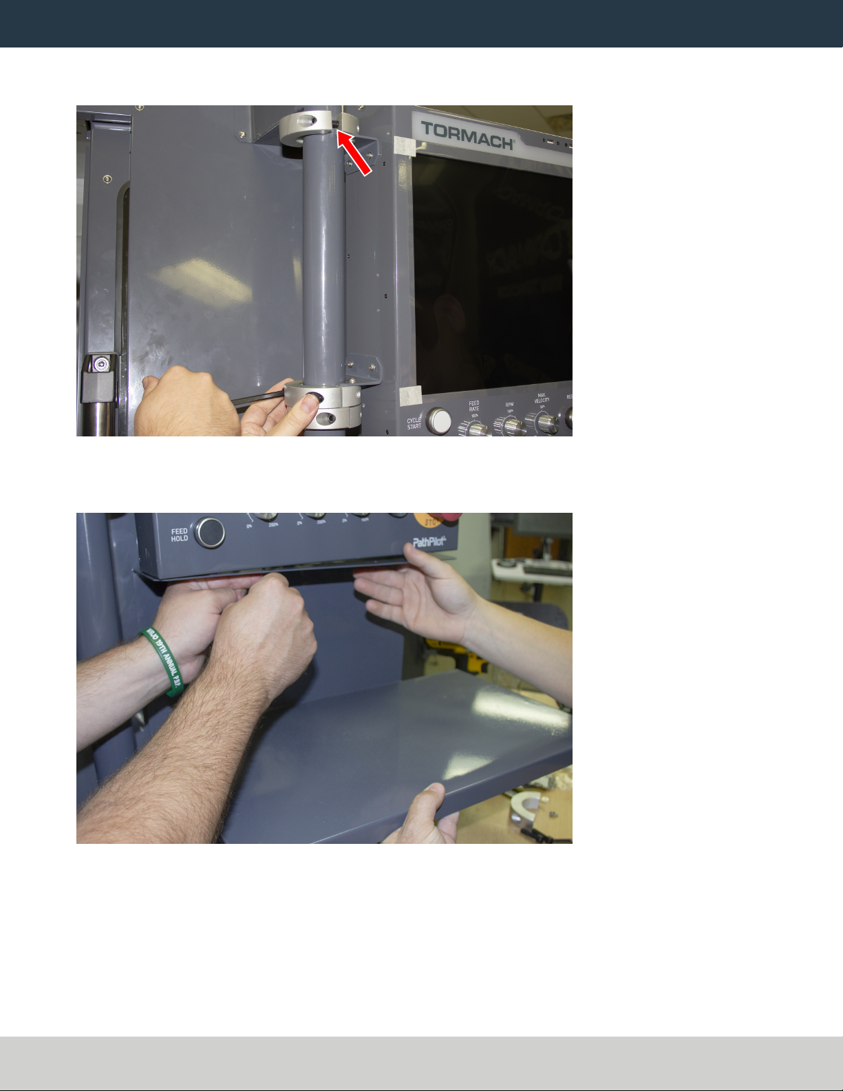
5. Find the keyboard tray that you set aside earlier. Then, attach it to the bottom of the controller, as shown in
the following image.
Figure 15: Attaching the keyboard tray to the bottom of the controller.
6. Loosely attach the opposite side of the split collar to the mounting arm using a 8 mm hex wrench.
7. Adjust the height and the angle of the console assembly as required.
8. Securely tighten all four split collars using a 8 mm hex wrench. Securely tighten all mount arm brackets
using a 2.5 mm hex wrench.
Page 12
©Tormach® 2022
Specifications subject to change without notice.
tormach.com
TD10715: Installation Guide: PathPilot Operator Console for 770 (0822A)

MAKE ELECTRICAL CONNECTIONS
MAKE ELECTRICAL CONNECTIONS
1. Find the provided Jog Pendant (PN50363).
2. Hang the jog pendant on its bracket (on the front of the controller) as shown in the following image.
Figure 16: Jog pendant on the front of the console assembly.
3. Route the loose end of the jog pendant to the back of the controller.
4. Find the provided power supply bracket. Then, attach it to the back of the controller with two M3 screws
using a Phillips screwdriver.
5. Find the provided power, Ethernet, emergency stop extension, and ATCUSB extension cables, and the WiFi
dongle. Then, connect them – and the jog pendant cable – to the controller as shown in the following image.
Figure 17: Controller connections.
Page 13
©Tormach® 2022
Specifications subject to change without notice.
tormach.com
TD10715: Installation Guide: PathPilot Operator Console for 770 (0822A)

MAKE ELECTRICAL CONNECTIONS
6. Put the power supply into the power supply bracket.
7. Find the provided corrugated tubing and piece of rubber.
8. Attach the piece of rubber to the bracket on the rear of the keyboard tray as shown in the following image.
Figure 18: Rubber attached to the bracket on the keyboard tray.
9. Put the loose ends of all cables from the controller into the corrugated tubing.
10. Push the corrugated tubing into the bracket on the rear of the keyboard tray.
Figure 19: Cords put into corrugated tubing, which is attached to the rear of the keyboard tray.
Page 14
©Tormach® 2022
Specifications subject to change without notice.
tormach.com
TD10715: Installation Guide: PathPilot Operator Console for 770 (0822A)

MAKE ELECTRICAL CONNECTIONS
11. Find the access panel on the machine stand as shown in the following image.
Figure 20: Access panel on the machine stand.
12. Remove the access panel using a 2 mm hex wrench, and discard the panel. Set the screws aside for later in
this procedure.
13. Find the provided access panel. Then, put the loose end of the corrugated tubing and all cords through it as
shown in the following image.
Figure 21: Loose end of corrugated tubing and all cords put through the access panel.
Page 15
©Tormach® 2022
Specifications subject to change without notice.
tormach.com
TD10715: Installation Guide: PathPilot Operator Console for 770 (0822A)
MAKE ELECTRICAL CONNECTIONS
14. Attach the access panel – with the corrugated tubing and all cords – to the machine stand with the screws
that you set aside in Step 12 using a 2 mm hex wrench.
Figure 22: Access panel attached to the machine stand.
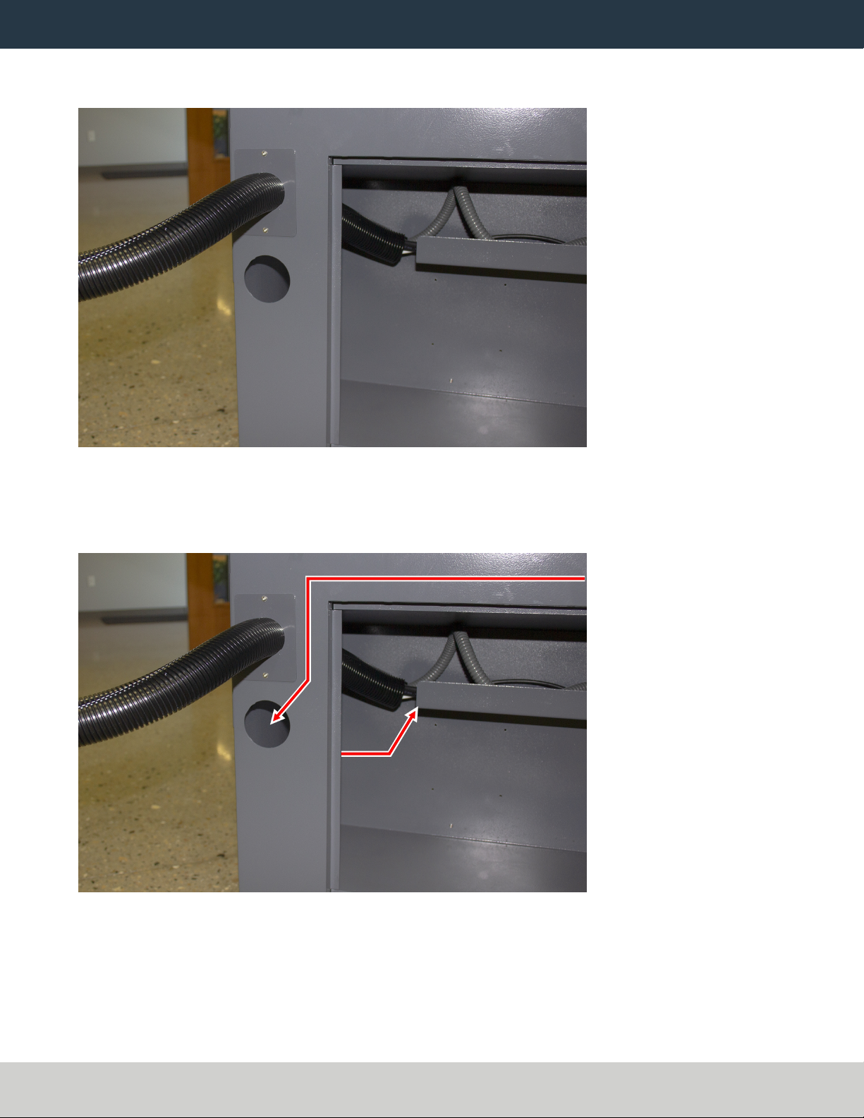
15. Route the loose end of all cords through the machine stand and out toward the rear of the machine.
16. Find the existing operator box cable that's preinstalled on the machine. Then, route it through the access
hole in the machine stand shown in the following image.
Figure 23: Preinstalled operator box cable routing.
17. Connect the operator box extension cable to the existing operator box cable (that you just routed into the
machine stand).
18. Connect the Ethernet cable to the Controller Communications port on the side of the electrical cabinet.
Page 16
©Tormach® 2022
Specifications subject to change without notice.
tormach.com
TD10715: Installation Guide: PathPilot Operator Console for 770 (0822A)
REASSEMBLE THE MACHINE
19. Connect the power cable to the Accessory Power port on the rear of the electrical cabinet.
20. From the ATC, remove and discard the existing USB cable. Then, route the loose end of the ATCUSB
extension cable from the controller to the ATC, and connect it in place of the original USB cable.
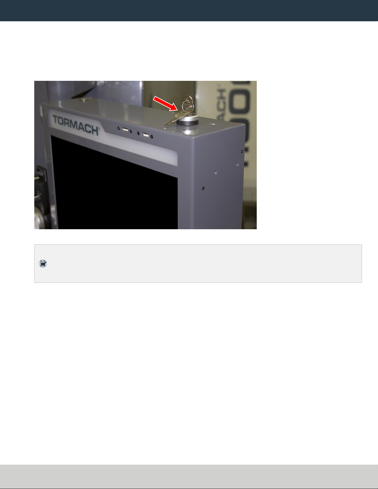
21. If you have an EU model of the operator console, find the provided set of keys, and put it into the top of the
operator console.
Figure 24: Key put into the controller.
Note: On EUmachines, the keys switch between run mode and setup mode. If you don't have an
EUmachine, you don't need the keys. For more information on operation modes, refer to the
Safety section of the EU machine operator's manual.
REASSEMBLE THE MACHINE
1. Put the right side window (that you set aside in "Prepare the Machine" (page4)) back into the right side
panel on the enclosure. Then, tighten the screws on the vertical window retainers
2. Power on the machine and the PathPilot controller.
a. Turn the Main Disconnect switch to ONon the side of the electrical cabinet.
b. Twist out the machine's red Emergency Stop button, which enables movement to the machine axes and
the spindle.
c. Press the Reset button.
d. Bring the machine out of reset and reference it.
Page 17
©Tormach® 2022
Specifications subject to change without notice.
tormach.com
TD10715: Installation Guide: PathPilot Operator Console for 770 (0822A)
TROUBLESHOOTING
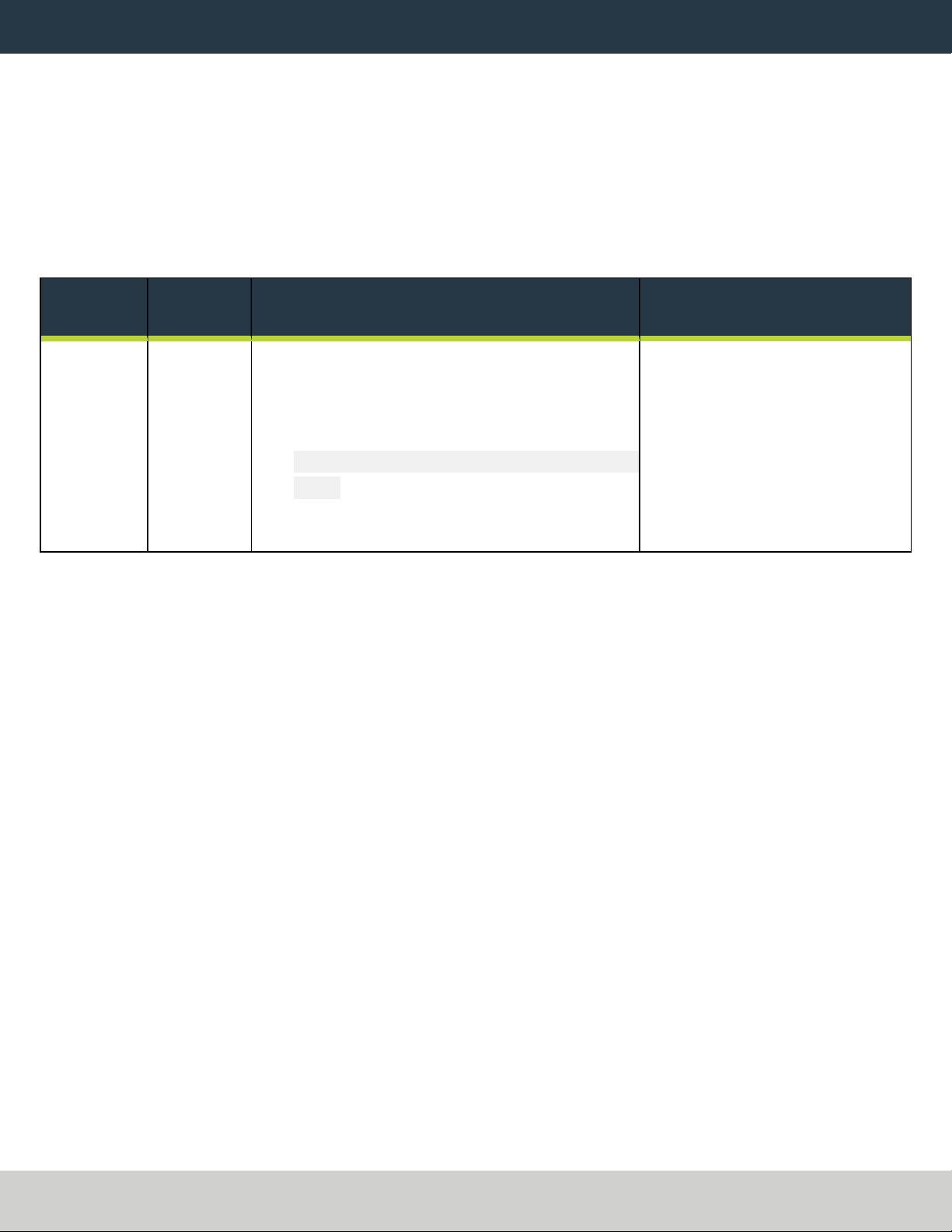
TROUBLESHOOTING
Problem
The touch screen does not respond to touch inputs on all or part of the screen's surface.
Cause
The sensitivity setting for the touch controller is too low.
Solutions
You Might
Need To... Probability How-To Steps Need More?
Adjust
touchscreen
sensitivity.
High 1. Verify that you have PathPilot v2.4.4 or
higher installed on your controller.
2. From the PathPilot interface, in the MDI
Line DRO field, type
ADMINTOUCHSCREENSENSITIVITY
1000 and press Enter. You can use a value
between 1 and 2047, but 1000 is generally
sufficient for most shop spaces.
The touchscreen is a resistive
type to prevent accidental
triggering from drops of coolant
on the screen. The resistive
touchscreen may need its
sensitivity adjusted when used in
a shop space with very high or
low humidity.
Page 18
©Tormach® 2022
Specifications subject to change without notice.
tormach.com
TD10715: Installation Guide: PathPilot Operator Console for 770 (0822A)

TROUBLESHOOTING
Problem
The console screen doesn't display an image or respond to the power button.
Cause
The console isn't receiving power.
Solutions
You Might
Need To... Probability How-To Steps Need More?
Examine
power input
to the
console.
High Examine the green LED on the
power brick for the console. If it's
not lit, examine the power cords
to the power brick.
If your console receives power from the
Accessory Input ports on the machine, look
for tripped breakers inside your machine's
electrical cabinet.
Test the
power
button
functionality.
Low Examine the green ring around
the power button. It should light
up when you press the power
button.
Page 19
©Tormach® 2022
Specifications subject to change without notice.
tormach.com
TD10715: Installation Guide: PathPilot Operator Console for 770 (0822A)

TROUBLESHOOTING
Problem
The console screen turns on, but is scrambled or illegible.
Cause
The BIOS isn't configured for the correct screen output.
Solutions
You Might Need
To... Probability How-To Steps Need More?
Configure the
display output
settings in BIOS.
High 1. Connect a VGA monitor
to the console.
2. Power the console on and
select the Delete key to
enter the BIOS.
3. From the Advanced tab,
select Display
Configuration.
4. Configure the display as
follows:
lPrimary IGFX Boot
Display:Auto
lLCD Panel Type:
1280x1024 LVDS
lPanel Channel:Dual
Channel
lPanel Color Depth: 24
Bit
5. Select the Esc key, go to
Save and Exit, and select
Save Changes and Reset.
This configuration problem can occur if your
console has a CMOS battery failure. Replace
the battery if it reoccurs.
Page 20
©Tormach® 2022
Specifications subject to change without notice.
tormach.com
TD10715: Installation Guide: PathPilot Operator Console for 770 (0822A)
Other manuals for pathpilot
2
This manual suits for next models
2
Table of contents
Other Tormach Music Mixer manuals


