Tormene Group LE+D SENSA T User manual

SENSA T Motion sensor. Turns on the light when the user opens the door and turns off it
automatically after a fixed time. The timer countdown is activated everytime a movement of the
door is detected. It can be installed in every tipe of swing door, folding door, drawer and light
sliding door.
SENSA M Motion and magnetic sensor. Turns on the light when the user opens the
door and turns off it automatically after a fixed time or recognizing a magnetic
contact. The timer countdown is activated everytime a movement of the door is detected.
It can be installed in every tipe of door and drawer. Suggested for heavy and damped
SENSA-T
SENSA-M
INDEX
1 - PRODUCT FEATURES
1.1 - TECHNICAL DATA
2 - PREPARATION ON DOOR
2.1 - SENSOR DIMENSIONS AND WORK ON DOOR
2.2 - POSITION OF REED CONTACT FOR MAGNET
2.3 - MAGNET INSTALLATION
3 - DESCRIPTION OF THE SENSOR
3.1 - DESCRIPTION
3.2 - USE OF THE SENSOR
4 - RADIO PROGRAMMING
5 - RADIO DELETION
6 - SETTING SENSOR SENSITIVITY
www .lightengineering.net
Tormene
group
LIGHT ENGINEERING + DESIGN SRL
Via Spagna, 6 - 35010 Vigonza (PD)
Ph. +39 049 0980809
Web: www.lightengineering.net
Tormene
group
07/2019_Rev 1.1
Battery
(insert rightway
round)
+
1.1 TECHNICAL DATA
Battery CR 2450
4,5 years with 30 activaction per day
Rolling code
433,92 MHz ISM
50m (20 m inside a building)
Motion recognition
SENSA MSENSA T
Motion recognition and magnetic contact
Power supply
Battery life
Code
Frequency
Range
Technology
1 - PRODUCT FEATURES
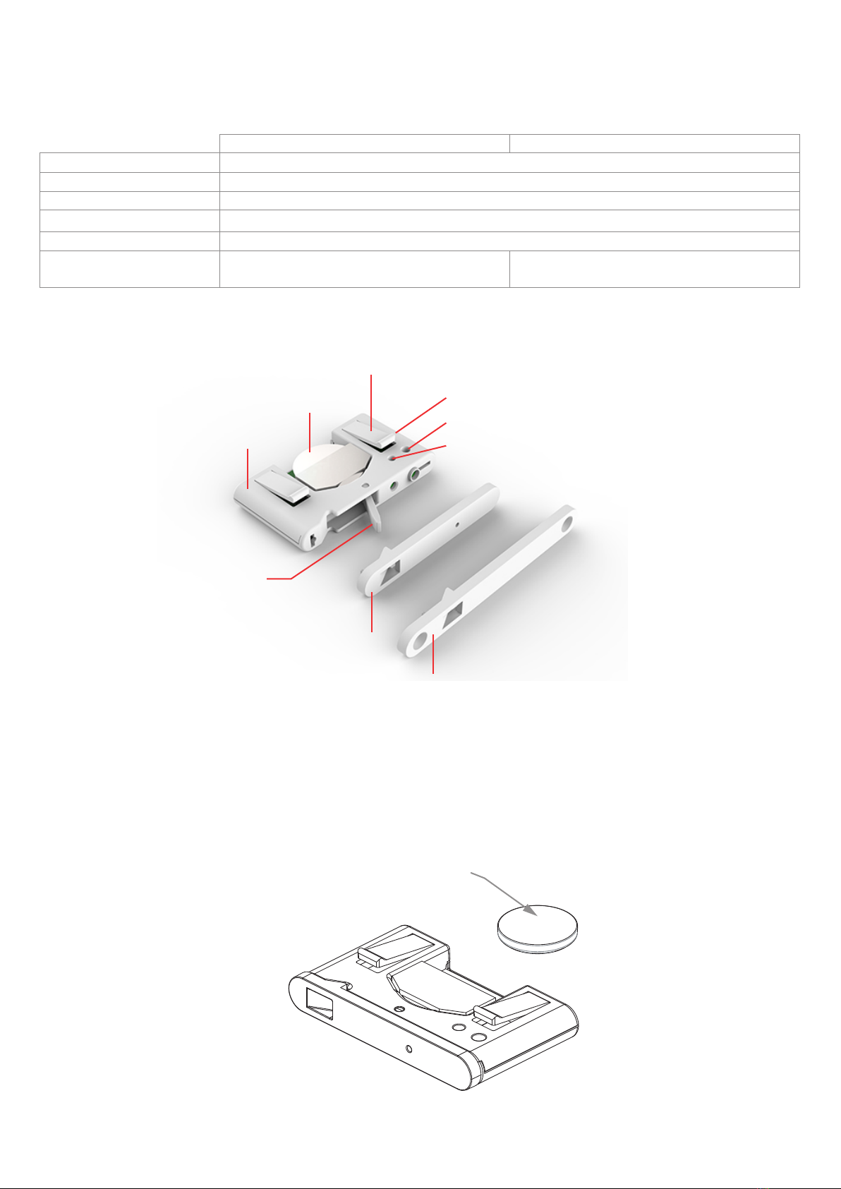
Top-screws
Top-joint
Extractoin
handle
Joint spring
Battery
Transmitter
433,92MHz
Magnetic sensor (SENSA M version)
Set-up button
Led
www.lightengineering.net
www.lightengineering.net

Battery
(insert rightway
round)
+
1.1 TECHNICAL DATA
Battery CR 2450
4,5 years with 30 activaction per day
Rolling code
433,92 MHz ISM
50m (20 m inside a building)
Motion recognition
SENSA MSENSA T
Motion recognition and magnetic contact
Power supply
Battery life
Code
Frequency
Range
Technology
1 - PRODUCT FEATURES
Top-screws
Top-joint
Extractoin
handle
Joint spring
Battery
Transmitter
433,92MHz
Magnetic sensor (SENSA M version)
Set-up button
Led
www.lightengineering.net
www.lightengineering.net

2.1 CUTTING ON THE DOOR
2.3 MAGNET INSTALLATION
(”SENSA M” VERSION)
2.2 POSITION OF REED CONTACT FOR MAGNET (”SENSA M” VERSION)
2 - PREPARATION ON DOOR
Reed sensor
for magnet
Preparation hole for
self-tapping screws
with countersunk head.
Max screw diameter 3,5mm
64,8mm
89,8mm
9,8mm
38,8mm
65mm 90mm
4mm
10mm
39mm
10mm
39mm
9,8mm
3,6mm
38,8mm
TOP-JOINT VERSION TOP-SCREWS VERSION
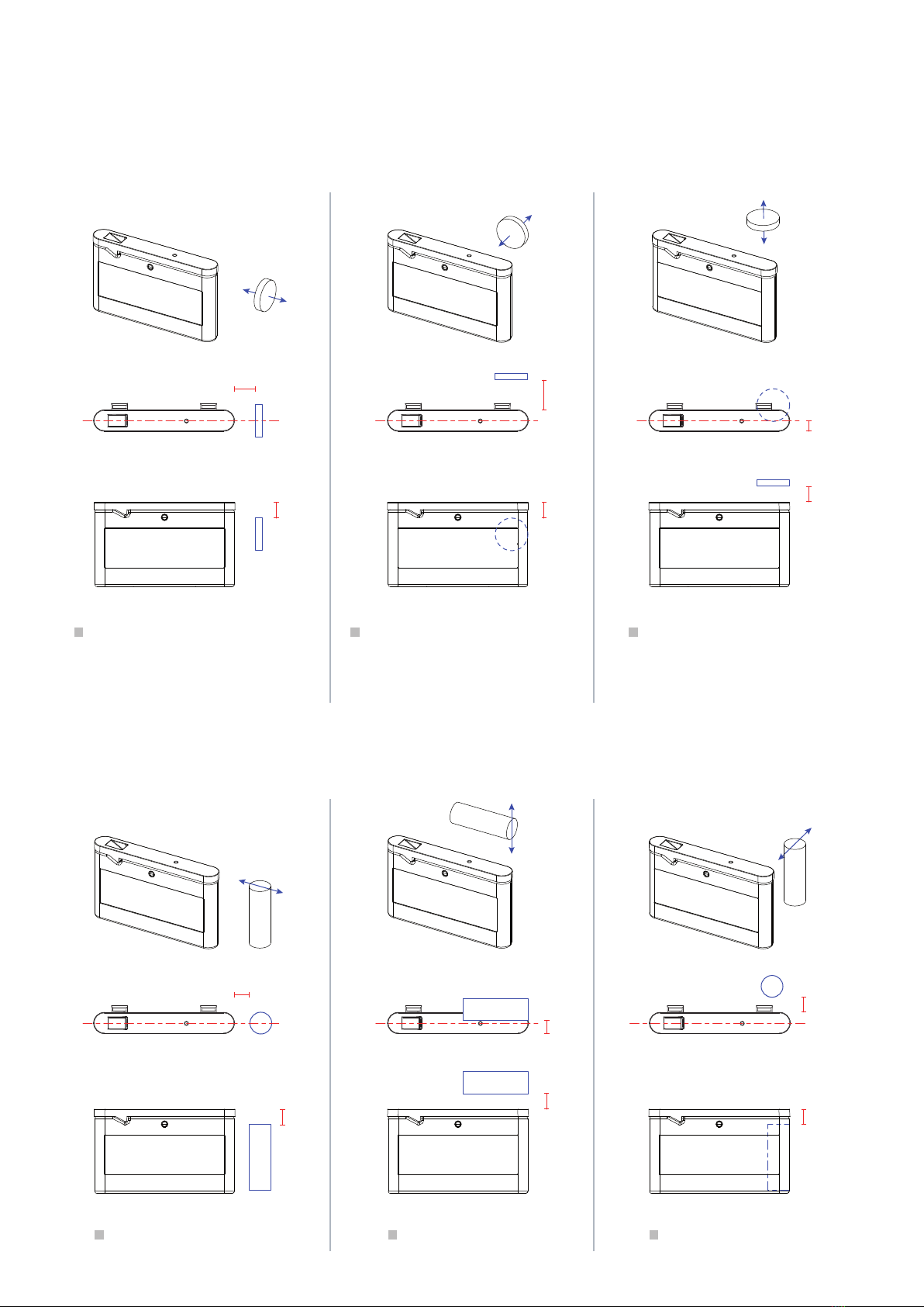
AXIAL MAGNET INSTALLATION (Sensa M + MAG153A or MAG225A)
DIAMETRICAL MAGNET INSTALLATION (Sensa M + MAG1030D)
POSITION A1 POSITION A2 POSITION A3
A1
B1
N
S
NN
S
S
N
S
N
S
N
S
D1
C1
C2
C3
D3
D2
B2
A2
A3
B3
POSITION D1 POSITION D2 POSITION D3
A1 (with MAG153A): max 15mm
A1 (con MAG225A): max 30mm
B1: 5mm
A2 (con MAG153A): max 15mm
A2 (con MAG225A): max 30mm
B2: 5mm
A3: 5mm
B3 (con MAG153A): max 15mm
B3 (con MAG225A): max 30mm
C1 : max 30mm
D1 : 0 mm
C2 : 0 mm
D2 : max 30mm
C3 : max 30mm
D3 : 0 mm
www.lightengineering.net
www.lightengineering.net
2.1 CUTTING ON THE DOOR
2.3 MAGNET INSTALLATION
(”SENSA M” VERSION)
2.2 POSITION OF REED CONTACT FOR MAGNET (”SENSA M” VERSION)
2 - PREPARATION ON DOOR
Reed sensor
for magnet
Preparation hole for
self-tapping screws
with countersunk head.
Max screw diameter 3,5mm
64,8mm
89,8mm
9,8mm
38,8mm
65mm 90mm
4mm
10mm
39mm
10mm
39mm
9,8mm
3,6mm
38,8mm
TOP-JOINT VERSION TOP-SCREWS VERSION
AXIAL MAGNET INSTALLATION (Sensa M + MAG153A or MAG225A)
DIAMETRICAL MAGNET INSTALLATION (Sensa M + MAG1030D)
POSITION A1 POSITION A2 POSITION A3
A1
B1
N
S
NN
S
S
N
S
N
S
N
S
D1
C1
C2
C3
D3
D2
B2
A2
A3
B3
POSITION D1 POSITION D2 POSITION D3
A1 (with MAG153A): max 15mm
A1 (con MAG225A): max 30mm
B1: 5mm
A2 (con MAG153A): max 15mm
A2 (con MAG225A): max 30mm
B2: 5mm
A3: 5mm
B3 (con MAG153A): max 15mm
B3 (con MAG225A): max 30mm
C1 : max 30mm
D1 : 0 mm
C2 : 0 mm
D2 : max 30mm
C3 : max 30mm
D3 : 0 mm
www.lightengineering.net
www.lightengineering.net
This manual suits for next models
1
Table of contents


