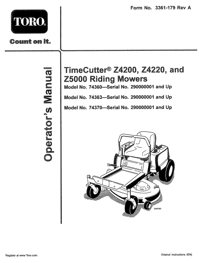
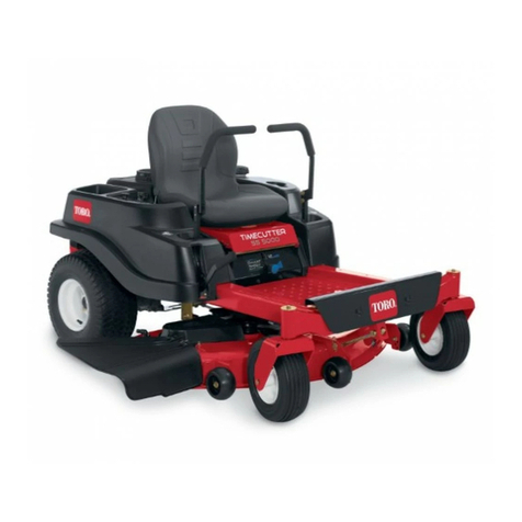
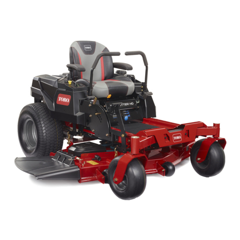
Toro 30555 User manual

FormNo.3383-271RevA
52inSideDischargeMower
Groundsmaster®200,3320and3280-D
SeriesTractionUnit
ModelNo.30555—SerialNo.314000001andUp
Registeratwww.Toro.com.
OriginalInstructions(EN)*3383-271*A

ThisproductcomplieswithallrelevantEuropeandirectives,
fordetailspleaseseetheseparateproductspecicDeclaration
ofConformity(DOC)sheet.
WARNING
CALIFORNIA
Proposition65Warning
Thisproductcontainsachemicalorchemicals
knowntotheStateofCaliforniatocausecancer,
birthdefects,orreproductiveharm.
Introduction
Thisrotary-bladelawncuttingdeckismountedtoaride-on
machineandisintendedtobeusedbyprofessional,hired
operatorsincommercialapplications.Itisprimarilydesigned
forcuttinggrassonwell-maintainedlawnsinparks,sports
elds,andoncommercialgrounds.Itisnotdesignedfor
cuttingbrush,mowinggrassandothergrowthalongside
highways,orforagriculturaluses.
Readthisinformationcarefullytolearnhowtooperateand
maintainyourproductproperlyandtoavoidinjuryand
productdamage.Youareresponsibleforoperatingthe
productproperlyandsafely.
YoumaycontactTorodirectlyatwww .Toro.comforproduct
andaccessoryinformation,helpndingadealer,ortoregister
yourproduct.
Wheneveryouneedservice,genuineToroparts,oradditional
information,contactanAuthorizedServiceDealerorToro
CustomerServiceandhavethemodelandserialnumbers
ofyourproductready.Themodelandserialnumbersare
stampedintoaplatelocatedonthecarrierframebehindthe
rightfrontcastorwheel.Writethenumbersinthespace
provided.
ModelNo.
SerialNo.
Thismanualidentiespotentialhazardsandhassafety
messagesidentiedbythesafetyalertsymbol(Figure1),
whichsignalsahazardthatmaycauseseriousinjuryordeath
ifyoudonotfollowtherecommendedprecautions.
Figure1
1.Safetyalertsymbol
Thismanualuses2otherwordstohighlightinformation.
Importantcallsattentiontospecialmechanicalinformation
andNoteemphasizesgeneralinformationworthyofspecial
attention.
©2013—TheToro®Company
8111LyndaleAvenueSouth
Bloomington,MN554202
Contactusatwww.Toro.com.
PrintedintheUSA.
AllRightsReserved

Contents
Introduction..................................................................2
Safety...........................................................................3
SafeOperatingPractices...........................................3
ToroMowerSafety..................................................5
SafetyandInstructionalDecals.................................6
Setup............................................................................8
1InstallingtheLiftArms..........................................8
2InstallingtheCarrierFrame....................................9
3InstallingtheCuttingUnit.....................................10
4InstallingtheCEDecal.........................................11
5InstallingRearWeight...........................................11
ProductOverview.........................................................12
Specications........................................................12
Attachments/Accessories........................................12
Operation....................................................................12
AdjustingtheHeight-of-Cut....................................12
AdjustingtheRollers...............................................12
CheckingtheGearBoxLubricant.............................13
AdjustingWeightTransfer.......................................13
UsingtheGrassDeector.......................................13
Maintenance.................................................................14
Lubrication............................................................14
SeparatingtheCuttingUnitfromtheTraction
Unit..................................................................15
ServicingtheBushingsintheCastorArms.................15
ServicingtheCastorWheelandBearing.....................15
CheckingforaBentBlade........................................16
RemovingtheCuttingBlade.....................................16
InspectingandSharpeningtheBlade.........................17
CheckingandCorrectingMismatchof
Blades...............................................................18
ReplacingtheGrassDeector..................................19
AdjustingtheIdlerPulley........................................19
ReplacingtheDriveBelt..........................................19
Troubleshooting...........................................................21
Safety
ThismachinemeetsorexceedsCENstandardEN836:1997,
ISOstandard5395:1990,andANSIB71.4-2004specications
ineffectatthetimeofproduction.
Improperuseormaintenancebytheoperatororownercan
resultininjury.Toreducethepotentialforinjury,comply
withthesesafetyinstructionsandalwayspayattentiontothe
safetyalertsymbol,whichmeansCAUTION,WARNING,or
DANGER-"personalsafetyinstruction."Failuretocomply
withtheinstructionmayresultinpersonalinjuryordeath.
SafeOperatingPractices
ThefollowinginstructionsareadaptedfromtheCEN
standardEN836:1997,ISOstandard5395:1990,andANSI
B71.4-2012.
Training
•Readtheoperator'smanualandothertrainingmaterial
carefully.Befamiliarwiththecontrols,safetysigns,and
theproperuseoftheequipment.Iftheoperatoror
mechaniccannotreadthelanguageofthismanual,itis
theowner'sresponsibilitytoexplainthismaterialtothem.
•Becomefamiliarwiththesafeoperationoftheequipment,
operatorcontrols,andsafetysigns.
•Alloperatorsandmechanicsshouldbetrained.The
ownerisresponsiblefortrainingtheusers
•Neverletchildrenoruntrainedpeopleoperateorservice
theequipment.Localregulationsmayrestricttheageof
theoperator.
•Theowner/usercanpreventandisresponsiblefor
accidentsorinjuriesoccurringtohimselforherself,other
people,orproperty.
SafeHandlingofFuels
•Toavoidpersonalinjuryorpropertydamage,use
extremecareinhandlinggasoline.Gasolineisextremely
ammableandthevaporsareexplosive.
•Extinguishallcigarettes,cigars,pipes,andothersources
ofignition.
•Useonlyanapprovedfuelcontainer.
•Neverremovefuelcaporaddfuelwiththeengine
running.
•Allowenginetocoolbeforerefueling.
•Neverrefuelthemachineindoors.
•Neverstorethemachineorfuelcontainerwherethereis
anopename,spark,orpilotlightsuchasonawater
heateroronotherappliances.
•Neverllcontainersinsideavehicleoronatruckor
trailerbedwithaplasticliner.Alwaysplacecontainerson
thegroundawayfromyourvehiclebeforelling.
3

•Removeequipmentfromthetruckortrailerandrefuelit
ontheground.Ifthisisnotpossible,thenrefuelsuch
equipmentwithaportablecontainer,ratherthanfroma
fueldispensernozzle.
•Keepthenozzleincontactwiththerimofthefueltank
orcontaineropeningatalltimesuntilfuelingiscomplete.
Donotuseanozzlelockopendevice.
•Iffuelisspilledonclothing,changeclothingimmediately.
•Neveroverllfueltank.Replacefuelcapandtighten
securely.
Preparation
•Evaluatetheterraintodeterminewhataccessoriesand
attachmentsareneededtoproperlyandsafelyperform
thejob.Onlyuseaccessoriesandattachmentsapproved
bythemanufacturer.
•Wearappropriateclothingincludinghardhat,safety
glassesandearprotection.Longhair,looseclothingor
jewelrymaygettangledinmovingparts.
•Inspecttheareawheretheequipmentistobeusedand
removeallobjectssuchasrocks,toysandwirewhichcan
bethrownbythemachine.
•Checkthatoperator'spresencecontrols,safetyswitches
andshieldsareattachedandfunctioningproperly.Donot
operateunlesstheyarefunctioningproperly.
Operation
•Neverrunanengineinanenclosedarea.
•Onlyoperateingoodlight,keepingawayfromholesand
hiddenhazards.
•Besurealldrivesareinneutralandparkingbrakeis
engagedbeforestartingengine.Onlystartenginefrom
theoperator'sposition.Useseatbeltsifprovided.
•Slowdownanduseextracareonhillsides.Besureto
travelintherecommendeddirectiononhillsides.Turf
conditionscanaffectthemachine'sstability.Usecaution
whileoperatingneardrop-offs.
•Slowdownandusecautionwhenmakingturnsandwhen
changingdirectionsonslopes.
•Neverraisedeckwiththebladesrunning.
•Neveroperatewithguardsnotsecurelyinplace.Be
sureallinterlocksareattached,adjustedproperly,and
functioningproperty.
•Donotchangetheenginegovernorsettingoroverspeed
theengine.
•Stoponlevelground,lowerthecuttingunits,disengage
drives,engageparkingbrake(ifprovided),shutoffengine
beforeleavingtheoperator'spositionforanyreason.
•Stopequipmentandinspectthebladesafterstriking
objectsorifanabnormalvibrationoccurs.Make
necessaryrepairsbeforeresumingoperations.
•Keephandsandfeetawayfromthecuttingunits.
•Lookbehindanddownbeforebackinguptobesureof
aclearpath.
•Nevercarrypassengersandkeeppetsandbystanders
away.
•Slowdownandusecautionwhenmakingturnsand
crossingroadsandsidewalks.Stopbladesifnotmowing.
•Donotoperatethemowerundertheinuenceofalcohol
ordrugs.
•Lightningcancausesevereinjuryordeath.Iflightning
isseenorthunderisheardinthearea,donotoperate
themachine;seekshelter.
•Usecarewhenloadingorunloadingthemachineintoa
trailerortruck.
•Usecarewhenapproachingblindcorners,shrubs,trees,
orotherobjectsthatmayobscurevision.
•Theoperatorshallturnonashingwarninglights,if
provided,whenevertravelingonapublicroad,except
wheresuchuseisprohibitedbylaw .
MaintenanceandStorage
•Disengagedrives,lowerthecuttingunits,movetraction
pedaltoNeutral,setparkingbrake,stopengineand
removekey.Waitforallmovementtostopbefore
adjusting,cleaningorrepairing.
•Cleangrassanddebrisfromcuttingunits,drives,mufer.
Letenginecoolbeforestoringanddonotstorenear
ames,andenginetohelppreventres.Cleanupoilor
fuelspillage.
•Letenginecoolbeforestoringanddonotstorenear
ame.
•Shutofffuelwhilestoringortransporting.Donotstore
fuelnearamesordrainindoors.
•Parkmachineonlevelground.Neverallowuntrained
personneltoservicemachine.
•Usejackstandstosupportcomponentswhenrequired.
•Carefullyreleasepressurefromcomponentswithstored
energy.
•Disconnectbatterybeforemakinganyrepairs.Disconnect
thenegativeterminalrstandthepositivelast.Reconnect
positiverstandnegativelast.
•Usecarewhencheckingblades.Wrapthebladesor
weargloves,andusecautionwhenservicingthem.Only
replaceblades.Neverstraightenorweldthem.
•Keephandsandfeetawayfrommovingparts.Ifpossible,
donotmakeadjustmentswiththeenginerunning.
•Chargebatteriesinanopenwellventilatedarea,away
fromsparkandames.Unplugchargerbeforeconnecting
ordisconnectingfrombattery.Wearprotectiveclothing
anduseinsulatedtools.
•Keepallpartsingoodworkingconditionandallhardware
tightened.Replaceallwornordamageddecals.
4
Hauling
•Usecarewhenloadingorunloadingthemachineintoa
trailerortruck.
•Usefullwidthrampsforloadingmachineintotraileror
truck.
•Tiethemachinedownsecurelyusingstraps,chains,cable,
orropes.Bothfrontandrearstrapsshouldbedirected
downandoutwardfromthemachine
ToroMowerSafety
ThefollowinglistcontainssafetyinformationspecictoToro
productsorothersafetyinformationthatyoumustknowthat
isnotincludedintheCEN,ISO,orANSIstandard.
Thisproductiscapableofamputatinghandsandfeetand
throwingobjects.Alwaysfollowallsafetyinstructionsto
avoidseriousinjuryordeath.
Useofthisproductforpurposesotherthanitsintendeduse
couldprovedangeroustouserandbystanders.
•Knowhowtostoptheenginequickly.
•Donotoperatethemachinewhilewearingtennisshoes
orsneakers.
•Wearingsafetyshoesandlongpantsisadvisableand
requiredbysomelocalordinancesandinsurance
regulations.
•Handlefuelcarefully.Wipeupanyspills.
•Checkthesafetyinterlockswitchesdailyforproper
operation.Ifaswitchshouldfail,replacetheswitch
beforeoperatingthemachine.
•Usingthemachinedemandsattention.Topreventloss
ofcontrol:
–Donotdriveclosetosandtraps,ditches,creeks,
embankments,orotherhazards.
–Avoidsuddenstopsandstarts.
–Whennearorcrossingroads,alwaysyieldthe
right-of-way.
–Lowerthecuttingunitwhengoingdownslopes.
•Thegrassdeectormustalwaysbeinstalledandinthe
lowestpositiononthesidedischargecuttingunit.Never
operatethemowerwithoutthedeectororentiregrass
collector.
•Ifthecuttingunitdischargeareaeverplugs,shutthe
engineoffbeforeremovingtheobstruction.
•Cutgrassslopescarefully.Donotstart,stop,orturn
suddenly.
•Donottouchtheengineormuferwhiletheengineis
runningorsoonafterithasstoppedbecausetheseareas
couldbehotenoughtocauseburns.
MaintenanceandStorage
•Checktheblademountingboltsfrequentlytobesurethat
theyaretightenedtospecication.
•Makesurethatallhydrauliclineconnectorsaretightand
allhydraulichosesandlinesareingoodconditionbefore
applyingpressuretothesystem.
•Keepyourbodyandhandsawayfrompinholeleaksor
nozzlesthatejecthydraulicuidunderhighpressure.
Usepaperorcardboard,notyourhands,tosearchfor
leaks.Hydraulicuidescapingunderpressurecanhave
sufcientforcetopenetratetheskinandcauseserious
injury.
•Beforedisconnectingorperforminganyworkonthe
hydraulicsystem,allpressureinthesystemmustbe
relievedbystoppingtheengineandloweringthecutting
unitstotheground.
•Iftheenginemustberunningtoperformamaintenance
adjustment,keephands,feet,clothing,andanypartsof
thebodyawayfromthecuttingunits,attachments,and
anymovingparts.Keepeveryoneaway.
•Donotoverspeedtheenginebychanginggovernor
settings.Toensuresafetyandaccuracy,havean
AuthorizedToroDistributorcheckthemaximumengine
speedwithatachometer.
•Theenginemustbeshutoffbeforecheckingtheoilor
addingoiltothecrankcase.
•Makesurethatthemowerfueltankisemptyifthe
machineistobestoredinexcessof30days.Donotstore
themowernearanyopenameorwheregasolinefumes
maybeignitedbyaspark.
•Performonlythosemaintenanceinstructionsdescribed
inthismanual.Ifmajorrepairsareeverneededor
ifassistanceisdesired,contactanAuthorizedToro
Distributor.
•Tomakesureofoptimumperformanceandcontinued
safetycerticationofthemachine,useonlygenuineToro
replacementpartsandaccessories.Replacementparts
andaccessoriesmadebyothermanufacturerscouldbe
dangerous,andsuchusecouldvoidtheproductwarranty.
5

SafetyandInstructionalDecals
Safetydecalsandinstructionsareeasilyvisibletotheoperatorandarelocatednearanyareaofpotential
danger.Replaceanydecalthatisdamagedorlost.
107-2916
1.Removetheignitionkeyandreadthe
Operator'sManualbeforeservicingor
performingmaintenance.
2.Thrownobjecthazard—donotoperate
themowerwiththedeectorupor
removed,keepthedeectorinplace;
keepbystandersasafedistancefrom
themachine.
3.Cutting/dismembermenthazardof
handorfoot,mowerblade—stayaway
frommovingparts.
120-6604
1.Thrownobjecthazard—keepbystandersawayfromthe
machine.
2.Cutting/dismembermenthazardofhand,mower
blade—stayawayfrommovingparts,keepallguardsand
shieldsinplace.
3.Cutting/dismembermenthazardoffoot,mowerblade—stay
awayfrommovingparts,keepallguardsandshieldsin
place.
93-6697
1.ReadtheOperator's
Manual.
2.AddSAE80w-90(API
GL-5)oilevery50hours.
105-9551
2WD:GM 228D = 0
GM 225 = 25 kg(55 lbs)
4WD:0
107-2908
1.Thrownobjecthazard—keepbystandersasafedistance
fromthemachine.
2.Thrownobjecthazard—donotoperatethemowerwiththe
deectoruporremoved,keepthedeectorinplace.
3.Cutting/dismembermenthazardofhandorfoot,mower
blade—stayawayfrommovingparts.
6

105-9551
2WD:GM 228D = 0
GM 225 = 25 kg(55 lbs)
4WD:0
105–9551
1.Warning—readthe
Operator'sManual.
2.Lowerthecuttingdeck
whentravelingdown
slopes.GM225unites
require25kg(55lbs)of
rearweight.GM228Dand
four-wheeldriveunitsdo
notrequirerearweight.
93-7818
1.Warning—readtheOperator'sManualforinstructionson
torquingthebladebolt/nutto115-149N-m(85-110ft-lb).
93–7819
1.Removetheignitionkeyandreadtheinstructionsbefore
servicingorperformingmaintenance.
2.Height-of-cut
99-5171
117–4979
1.Entanglementhazard,belt—stayawayfrommovingparts,
keepallguardsandshieldsinplace.
107-2915
1.Entanglementhazard,shaft-keepbystandersasafe
distancefromthemachine.
107-2926
1.Cutting/dismembermenthazard,impeller—stayawayfrom
movingparts.
2.Thrownobjecthazard—keepbystandersasafedistance
fromthemachine.
7

Setup
LooseParts
Usethechartbelowtoverifythatallpartshavebeenshipped.
ProcedureDescriptionQty.Use
Right-handliftarm1
Left-handliftarm1
Spacer4
Pivotpin2
1
Cotterpin(5/32x1-3/4inches)2
Installtheliftarms.
Rearcradle2
Spacer2
Bolt(3/8x2inches)6
Flangenut(3/8inch)6
2
Bolt(1/2x1-1/2inches)3
Installthecarrierframe.
Clevispins4
Hairpincotter4
3Cushionshim3
Installthecuttingunit.
4Decal1ApplyforCEcompliance.
5Nopartsrequired–Installrearweight.
MediaandAdditionalParts
DescriptionQty.Use
PartsCatalog1
Operator'sManual1Reviewthematerialandsaveinanappropriateplace:
DANGER
IftheengineisstartedandthePTOshaftisallowed
torotate,seriousinjurycouldresult.
DonotstarttheengineandengagethePTOlever
whenthePTOshaftisnotconnectedtothegear
boxonthecuttingunit.
Note:Determinetheleftandrightsidesofthemachine
fromthenormaloperatingposition.
Note:Wheninstallingthe52inchdeckontoa
Groundsmaster200Seriestractionunit,theWeightTransfer
Kit,ToroPartNumber70-8090mustbeinstalled.
1
InstallingtheLiftArms
Partsneededforthisprocedure:
1Right-handliftarm
1Left-handliftarm
4Spacer
2Pivotpin
2Cotterpin(5/32x1-3/4inches)
Procedure
1.Ononesideofthetractionunit,loosen(donot
remove)thewheelnutssecuringthewheelandtire
assemblytothefrontwheelstuds.
8

2.Jackupthemachineuntilthefrontwheelisoffofthe
oor.Usejackstandsorblockthemachinetoprevent
itfromaccidentallyfalling.
3.Removethewheelnutsandslidethewheelandtire
assemblyoffofthestuds.
4.Mountaliftarmtothepivotbracketwith2spacers,
apivotpin,andacotterpin(5/32x1-3/4inches).
Mounttheliftarmwiththebendpositionedoutward
(Figure2).
2G010540
12
3
4
Figure2
1.Liftarm3.Pivotbracket
2.Spacer(2)4.Pivotpin
5.Mounttherearoftheliftarmtotheliftcylinderwitha
pivotpinand2cotterpins(suppliedwiththetraction
unit)(Figure3).
G010541
1
2
33
Figure3
1.Cylinderpin3.Cotterpin
2.Cylinderend
6.Removethecotterpinsfromtheclevispinsholding
thebrakestrutsandyokestogether,anddiscardthe
cotterpins.Keepingtheclevispininplace,installthe
shortendofthespringintotheholeintheclevispinto
retainthepartstogether.Connecttheotherendofthe
springstotheslottedholesintheliftarms(Figure4).
G010542
1
2
Figure4
1.Brakereturnspring2.Slottedhole
7.Repeattheprocedureontheoppositesideofthe
machine.
2
InstallingtheCarrierFrame
Partsneededforthisprocedure:
2Rearcradle
2Spacer
6Bolt(3/8x2inches)
6Flangenut(3/8inch)
3Bolt(1/2x1-1/2inches)
Procedure
Note:GreasethecastorwheelshaftwithNo.2greaseafter
installingandafterinitialoperationofthemachine.
1.Carrierframeisshippedupsidedown.Turnframe
overbeforeinstallation.
2.Removethelynchpinand2thrustwashersshippedon
eachcastorwheelassembly.Leave2thrustwasherson
eachshaft,inserttheshaftsintotheframemounting
tube,andinstallthethrustwashersandlynchpin
(Figure5).
9

G010543
1
2
3
4
Figure5
1.Castorwheelassembly3.Thrustwashers
2.Carrierframe4.Lynchpin
3.Mountarearcradletoeachliftarmwith3bolts(3/8x
2inches),spacers,andangenutsasshowninFigure6.
Figure6
1.Liftarm3.Rearcradle
2.Carrierframe4.Spacer
Note:Iftherearcradlemountingholesarenotin
theliftarms,usethedimensionsshowninFigure7to
locate,mark,anddrillthe3holes(10.31mm(13/32
inch)diameter)requiredineachliftarm.
G010545
1
2
3
4
5
6
Figure7
1.31.75mm(1.250inches)4.12.7mm(0.500inch)
2.62mm(2.438inches)5.25.4mm(1.000inch)
3.(12.7mm(0.500inch)6.10.31mm(0.406inch)
diameter(3)
4.Slidethecarrierframeontotheliftarmsaligningthe
mountingholes.Secureeachsideofthecarrierframe
totheliftarmswith3bolts(1/2x1-1/2inches).
Torquetheboltsto95-108N-m(70-80ft-lb)(Figure6).
3
InstallingtheCuttingUnit
Partsneededforthisprocedure:
4Clevispins
4Hairpincotter
3Cushionshim
Procedure
1.MakesurethatthePTOshaftonthetractionunit
clearsthecuttingunitframe,engagetheparkingbrake,
putthetractionpedalinneutral,thePTOleverinthe
Offposition,starttheengine,andraisetheframe.
2.Stopengineandslidethecuttingunitundertheframe.
3.Removethe2boltsandlockwasherssecuringthePTO
guardmountingbracketstothegearbox(Figure8).
Retainthefastenersforfutureinstallation.
10

Figure8
1.PTOguard2.Gearbox
4.SlidethePTOshaftguardontothePTOshaft,
positioningtheguardasshowninFigure8.
5.SlidethemalePTOshaftintothefemalePTOshaft.
AlignthegearcaseinputshaftwiththePTOshaftand
slidethemtogether.Securethemwiththerollpinand
tightentheboltsandlocknuts.
6.AttachthePTOshaftguardtothegearboxwiththe2
boltsandlockwasherspreviouslyremoved.
7.Lowerthecarrierframeandinstall4clevispins
throughthedesiredheight-of-cutbracketholesand
framebrackets.Secureall4pinswithhairpincotters
(Figure9).
Note:OntheGM3280-Dand3320theenginemust
bestartedtolowerthecarrierframe.
Figure9
1.25mm(1inch)6.89mm(3-1/2inches)
2.38mm(1-1/2inches)7.102mm(4inches)
3.51mm(2inches)8.Grassdeector
4.64mm(2-1/2inches)9.Springhinges
5.76mm(3inches)
8.Checktomakesurethatthefrontheight-of-cutpinsare
restingproperlyontheframecushions(Figure10).If
thepinsarenotrestingproperly,placeashimorshims
underthecushiontoraiseitforproperalignment.
Figure10
1.Framecushions
4
InstallingtheCEDecal
Partsneededforthisprocedure:
1Decal
Procedure
ApplythedealtothecuttingunitforCEcompliance
5
InstallingRearWeight
NoPartsRequired
Procedure
TwoWheelDriveGroundsmaster200Series,3280-D,and
3320tractionunitscomplywiththeANSIB71.4-2004
Standardwhenequippedwithrearweight.Refertothe
chartinthetractionunitOperator'sManualtodeterminethe
combinationsofweightrequired.Orderthepartsfromyour
localAuthorizedToroDistributor.
FourWheelDriveGroundsmaster200Seriesand3280-D
tractionunitsdonotneedadditionalrearweighttocomply
withtheANSIB71.4-2004Standard.
11

ProductOverview
Specications
Note:Specicationsanddesignaresubjecttochange
withoutnotice.
Widthof
Cut
1.314m(51-3/4inches)
Height
ofCut
Adjustablefrom25to102mm(1to4inches)in1/2
inch(13mm)increments
Blade
Tip
Speed
15,525ft/minute@3250engineRPM
Cutting
Blades
3heat-treatedsteelblades,each4.8mm(3/16inch)
thickand457mm(18inches)long
Pneumatic
Wheels
203mm(8inches)diametergreaseableroller
bearings(inatedto138-207kPa[20-30psi])
Drive
System
PTOdrivengearboxtransmitspowerthrougha"AA"
sectionbelttoallbladespindles.
Net
Weight
153kg(338lbs.)
Attachments/Accessories
AselectionofToroapprovedattachmentsandaccessoriesis
availableforusewiththemachinetoenhanceandexpand
itscapabilities.ContactyourAuthorizedServiceDealeror
Distributororgotowww .Toro.comforalistofallapproved
attachmentsandaccessories.
Operation
Note:Determinetheleftandrightsidesofthemachine
fromthenormaloperatingposition.
AdjustingtheHeight-of-Cut
Theheight-of-cutisadjustablefrom25to102mm(1to4
inches)in13mm(1/2inch)incrementsbyrelocating4clevis
pinsindifferentholelocations(Figure11).
Figure11
1.25mm(1inch)6.89mm(3-1/2inches)
2.38mm(1-1/2inches)7.102mm(4inches)
3.51mm(2inches)8.Grassdeector
4.64mm(2-1/2inches)9.Springhinges
5.76mm(3inches)
AdjustingtheRollers
Note:Ifthecuttingunitistobeusedinthe25mm(1inch)
or38mm(1-1/2inches)height-of-cutsetting,therearcutting
unitrollersmustberepositionedinthetopbracketholes.
1.Removethecotterpinssecuringtherollershaftsto
theundersideofthedeck.
2.Slidetheshaftsoutofthelowerbracketholes,alignthe
rollerswiththetopholes,andinstalltheshafts.
3.Installthecotterpinstosecuretheassemblies.
12

CheckingtheGearBox
Lubricant
ThegearboxisdesignedtooperateonSAE80-90wt.gear
lube.Althoughthegearboxisshippedwithlubricantfrom
thefactory,checkthelevelbeforeoperatingthecuttingunit.
1.Positionthemachineandcuttingunitonalevelsurface.
2.Removethedipstick/llplugfromthetopofthegear
box(Figure12)andmakesurethatthelubricantis
betweenthemarksonthedipstick.Ifthelubricant
levelislow ,addenoughlubricantuntilthelevelis
betweenthemarks.
Figure12
1.Dipstick/llplug
AdjustingWeightTransfer
OnGroundsmaster3280-Dand3320modelsonly,referto
thetractionunitOperator'sManualfortheproceduretoadjust
thecounterbalancepressureforbestperformance.
UsingtheGrassDeector
DANGER
Withoutthegrassdeectormountedinplace,you
andothersareexposedtobladecontactandthrown
debris.Contactwiththerotatingmowerblade(s)
andthrowndebriswillcauseinjuryordeath
•Neverremovethegrassdeectorfromthemower
becausethegrassdeectorroutesmaterialdown
towardtheturf.Ifthegrassdeectorisever
damaged,replaceitimmediately.
•Neverputyourhandsorfeetunderthemower.
•Neveroperatethemowerwiththedeector
removedfromthecuttingunitortied/blocked
inaraisedposition.
Note:Thedeectorisspringloadedintoitsdownward
normaloperatingposition(Figure11),buttheoperatorcan
temporarilyswingitoutofthewaytofacilitateloadingina
trailerorwhenotherwisenecessary.
13

Maintenance
Important:Thefastenersonthecoversofthismachine
aredesignedtoremainonthecoverafterremoval.
Loosenallofthefastenersoneachcoverafewturnsso
thatthecoverisloosebutstillattached,thengoback
andloosenthemuntilthecovercomesfree.Thiswill
preventyoufromaccidentallystrippingtheboltsfree
oftheretainers.
Lubrication
Thecuttingunitmustbelubricatedregularly.Ifthemachine
isoperatedundernormalconditions,lubricatethecastor
bearingsandbushingswithNo.2generalpurposelithium
basegreaseormolybdenumbasegreaseafterevery8hoursof
operationordaily,whichevercomesrst.Allotherbearings,
bushings,andthegearboxmustbelubricatedafterevery50
hoursofoperation.
1.Lubricatethefollowingareas:
•castorspindlebushings(Figure13)
•castorwheelbearings(Figure13)
Figure13
•rightandleftliftarmpivotpins(Figure14)
Figure14
•bladespindlebearings(Figure15)
Figure15
2.Positionthemachineandcuttingunitonalevelsurface
andlowerthecuttingunit.Removethedipstick/ll
plugfromthetopofthegearbox(Figure16)and
makesurethatthelubricantisbetweenthemarkson
thedipstick.Ifthelubricantlevelislow,addSAE
80-90wt.gearlubeuntilthelevelisbetweenthemarks.
SAE80-90wt.syntheticgearlubemaybeusedasan
alternative.
Figure16
14

SeparatingtheCuttingUnit
fromtheTractionUnit
1.Positionthemachineonalevelsurface,raisethecutting
unit,engagetheparkingbrake,putthetractionpedal
inneutral,thePTOleverintheOffposition,shutthe
engineoff,andremovetheignitionkey.
2.Lowerthecuttingunitandremovethe4pinsfromthe
height-of-cutbrackets
3.Starttheengineandraisethecuttingunitframe.
4.Stoptheengineandslidethecuttingunitawayfrom
thetractionunitandcarrierframe,separatingthemale
andfemalesectionsofthePTOshaft(Figure17).
Figure17
1.PTOshaft
DANGER
IftheengineisstartedandthePTOshaftis
allowedtorotate,seriousinjurycouldresult.
DonotstarttheengineandengagethePTO
leverwhenthePTOshaftisnotconnectedto
thegearboxonthecuttingunit.
5.Thedeckcarrierframemustberemovedifthetraction
unitwillbeusedwithanyotheraccessory.
ServicingtheBushingsinthe
CastorArms
Thecastorarmshavebushingspressedintothetopand
bottomportionofthetubewhich,aftermanyhoursof
operation,willwear.Tocheckthebushings,movethecastor
forkbackandforthandfromsidetoside.Ifthecastorshaft
islooseinsidethebushings,thebushingsarewornandmust
bereplaced.
1.Raisethecuttingunitsothatthewheelsareoffofthe
oorandblockitsothatitcannotaccidentallyfall.
2.Removethelynchpinandthrustwashersfromthetop
ofthecastorspindle.
3.Pullthecastorspindleoutofthemountingtube.Allow
thethrustwasherstoremainonthebottomofthe
spindle.
4.Insertapinpunchintothetoporbottomofthe
mountingtubeanddrivethebushingoutofthetube
(Figure18).Alsodrivetheotherbushingoutofthe
tube.Cleantheinsideofthemountingtubetoremove
anydirt.
G010553
1
2
Figure18
1.Lynchpin2.Thrustwashers
5.Applygreasetotheinsideandoutsideofthenew
bushings.Usingahammerandatplate,drivethe
bushingsintothemountingtube.
6.Inspectthecastorshaftforwearandreplaceitifitis
damaged.
7.Pushthecastorshaftthroughthebushingsand
mountingtube.Slidethespacersontotheshaftand
secureitwiththelynchpin.
Important:Whenthebushingsareinstalled,the
insidediametermaycollapseslightly,andthis
maynotallowthecastorshafttobeinstalled.If
thecastorspindledoesnotslidethroughthenew
bushingsandmountingtube,reambothbushings
toaninsidediameterof1.126inches.
ServicingtheCastorWheel
andBearing
Thecastorwheelrotatesonahigh-qualityrollerbearingand
issupportedbyaspannerbushing.Evenaftermanyhours
ofuse,providedthatthebearingwaskeptwelllubricated,
bearingwearwillbeminimal.However,failuretokeepthe
bearinglubricatedwillcauserapidwear.Awobblycastor
wheelusuallyindicatesawornbearing.
15

1.Removethelocknutfromtheboltholdingthecastor
wheelassemblybetweenthecastorfork(Figure19).
Graspthecastorwheelandslidetheboltoutofthe
fork.
Note:Accountfor2thrustwashers.
2.Tipthewheeltothesideandallowthespannerbushing
(Figure19)tofallout.
Figure19
1.Castorfork4.Spannerbushing
2.Thrustwasher5.Rollerbearing
3.Bearingretainer
3.Removeonebearingretainerfromthewheelhuband
allowthebearingtofallout.Removethebearing
retainerfromtheoppositesideofthewheelhub
(Figure19).
4.Inspectthebearing,spannerbushing,andwheelfor
wear.Replacewornordamagedparts.
5.Toassembletheparts,slidethespannerbushing
throughthehubassembly.
6.Mountthecastorwheelassemblyandwashersbetween
theforkandinserttheboltandlocknut.Tightenthe
boltandlocknutuntilthespannerbushingandwashers
bottomoutagainsttheinsideofthecastorfork.
7.Pumpgreasethroughthegreasettingonthewheel
untilthebearingisgreasedthoroughly.
CheckingforaBentBlade
1.Positionthemachineonalevelsurface,raisethecutting
unit,engagetheparkingbrake,putthetractionpedal
inneutral,thePTOleverintheOffposition,shutthe
engineoff,removetheignitionkey,anddisconnectthe
wiresfromthesparkplugs.Blockthecuttingunitto
preventitfromaccidentallyfalling.
2.Rotatethebladeuntiltheendsfaceforwardand
backward.Measurefromtheinsideofthecuttingunit
tothecuttingedgeatthefrontoftheblade(Figure20),
andrememberthisdimension.
G010549
Figure20
3.Rotatetheoppositeendofthebladeforward.Measure
betweenthecuttingunitandcuttingedgeofthe
bladeatthesamepositionasinstep2Thedifference
betweenthedimensionsobtainedinsteps2and3must
notexceed3mm(1/8inch).Ifthedimensionexceeds
3mm(1/8inch),replacethebladebecauseitisbent;
refertoRemovingtheCuttingBlade.
RemovingtheCuttingBlade
Theblademustbereplacedifasolidobjectishit,the
bladeisout-of-balance,worn,orbent.Alwaysusegenuine
Tororeplacementbladestoensuresafetyandoptimum
performance.Neverusebladesmadebyothermanufacturers
becausetheycouldbedangerous.
DANGER
Awornordamagedbladecanbreak,andapiece
ofthebladecouldbethrownintotheoperator's
orbystander'sarea,resultinginseriouspersonal
injuryordeath.
•Inspectthebladeperiodicallyforwearor
damage.
•Donottrytostraightenabladethatisbent.
•Neverweldabrokenorcrackedblade.
•Replaceawornordamagedbladewitha
newTorobladetoensurecontinuedsafety
certicationoftheproduct.
1.Positionthemachineonalevelsurface,raisethe
cuttingunit,engagetheparkingbrake,putthetraction
pedalinneutral,thePTOleverintheOffposition,
shuttheengineoff,andremovetheignitionkey.Block
thecuttingunittopreventitfromaccidentallyfalling.
2.Grasptheendofthebladeusingaragorthickly
paddedglove.Removethebladebolt,anti-scalpcup,
andbladefromthespindleshaft(Figure21).
16

G010555
1
2
Figure21
1.Bladebolt2.Anti-scalpcup
3.Installtheblade-sailfacingtowardthecuttingunit-with
theanti-scalpcupandbladebolt.Tightentheblade
boltto85-110ft-lb(115-149N-m).
InspectingandSharpeningthe
Blade
Twoareasmustbeconsideredwhencheckingandservicing
thecuttingblade:thesailandthecuttingedge.Bothcutting
edgesandthesail,whichistheturnedupportionopposite
thecuttingedge,contributetoagoodquality-of-cut.The
sailisimportantbecauseitpullsgrassupstraight,thereby
producinganevencut.However,thesailwillgraduallywear
downduringoperation,andthisconditionisnormal.Asthe
sailwearsdown,thequality-of-cutwilldegradesomewhat,
althoughthecuttingedgesaresharp.Thecuttingedgeof
theblademustbesharpsothatthegrassiscutratherthan
torn.Adullcuttingedgeisevidentwhenthetipsofthegrass
appearbrownandshredded.Sharpenthecuttingedgesto
correctthiscondition.
1.Positionthemachineonalevelsurface,raisethe
cuttingunit,engagetheparkingbrake,putthetraction
pedalinneutral,thePTOleverintheOffposition,
shuttheengineoff,andremovetheignitionkey.Block
thecuttingunittopreventitfromaccidentallyfalling.
2.Examinethecuttingendsofthebladecarefully,
especiallywheretheatandcurvedpartsoftheblade
meet(Figure22).Sincesandandabrasivematerialcan
wearawaythemetalthatconnectstheatandcurved
partsoftheblade,checkthebladebeforeusingthe
machine.Ifwearisnoticed(Figure22),replacethe
blade;refertoRemovingtheCuttingBlade.
Figure22
1.Cuttingedge3.Wear/slotforming
2.Curvedarea/sail4.Crack
WARNING
Ifthebladeisallowedtowear,aslotwillform
betweenthesailandatpartoftheblade
(Figure22).Eventually,apieceoftheblade
maybreakoffandbethrownfromunderthe
housing,possiblyresultinginseriousinjuryto
yourselforbystanders.
•Inspectthebladeperiodicallyforwearor
damage.
•Replaceawornordamagedbladewitha
newTorobladetoensurecontinuedsafety
certicationoftheproduct.
3.Examinethecuttingedgesofallblades.Sharpenthe
cuttingedgesiftheyaredullornicked.Sharpenonly
thetopsideofthecuttingedgeandmaintainthe
originalcuttingangletoensuresharpness(Figure23).
Thebladewillremainbalancedifthesameamountof
metalisremovedfrombothcuttingedges.
Figure23
1.Sharpenatoriginalangle
Note:Removethebladesandsharpenthemona
grinder;refertoRemovingtheCuttingBlades.After
sharpeningthecuttingedges,installthebladewiththe
anti-scalpcupandbladebolt.Thebladesailsmustbe
ontopoftheblade.Tightenthebladeboltto115-149
N-m(85-110ft-lb).
17

CheckingandCorrecting
MismatchofBlades
Ifonecuttingbladecutslowerthantheothers,correctthem
asfollows:
1.Lowerthecuttingunitontoalevelsurface,engagethe
parkingbrake,putthetractionpedalinneutral,the
PTOleverintheOffposition,shuttheengineoff,
andremovetheignitionkey.Makesurethatthetire
pressureisequalonalltires.
2.Raisetheheight-of-cuttothe102mm(4inches)
position;refertoAdjustingtheHeight-of-Cut.
3.Rotatethebladessothatthetipslineupwithone
another.Thetipsoftheadjacentbladesmustbewithin
3mm(1/8inch)ofeachother.Ifthetipsarenot
within3mm(1/8inch)ofeachother,proceedtostep
10andaddshimsbetweenthespindlehousingand
bottomofthecuttingunit.
4.Checktomakesurethatthefrontheight-of-cutpins
arerestingproperlyontheframecushions.Ifthepins
arenotrestingproperly,placeashimorshimsunder
thecushiontoraiseitforproperalignment.
5.Positionall3bladesintheAposition(Figure24)and
measurefromthelevelsurfacetothebottomofthetip
endofeachblade(Figure25).
G010556
A
B
C
A
B
CA
B
C
Figure24
G010557
1
Figure25
1.Measurefrombladetiptoalevelsurface.
6.NotethemeasurementattainedatA,rotatetheblades
totheBposition(Figure24),measurethedistance
ofallofthebladestothelevelsurface,andnotethe
dimensions(Figure25).
7.RotatethebladestotheCposition,measure,andnote
thedistancemeasured(Figure24andFigure25).
8.Comparethemeasurementsatvariouspositions.All
dimensionsmustbeequalwithin6mm(1/4inch)
fromany2adjacentblades.Thedifferencebetween
thedimensionsofall3bladesmustnotexceed10mm
(3/8inch).Ifthedifferenceexceedsspecications,
proceedtostep9.
9.Removethebolts,atwashers,andlocknutsfrom
theouterspindleintheareawheretheshimsmustbe
added.Toraiseorlowertheblade,addashim,Part
No.3256-24,betweenthespindlehousingandbottom
ofthecuttingunit.Continuecheckingthealignmentof
thebladesandaddingshimsuntilthetipsoftheblades
arewithintherequireddimension.
10.Equalizetheside-to-sidemeasurementsasfollows:
A.Cuttingunitsusuallyoperatedat25to51mm(1
to2inches)height-of-cutshouldhavethelowside
ofthecuttingunitraised.Removethelynchpin
securingthecastorwheelonthelowend(Figure
26)andremovethecastorassembly.
G010553
1
2
Figure26
1.Lynchpin2.Thrustwashers(as
required)
B.Transferonethrustwasherfromthetopside
ofthecastorshafttothelowerside,installthe
castorassembly,andcomparethebladeheightof
allblades;refertosteps3through7.Continue
addingthrustwashersiftheheightstilldoesnot
meettherequirements.
C.Ifthecuttingunitisoperatedatthe51mmto102
mm(2to4inches)height-of-cut,lowerthehigh
sideofthecuttingunit.Removethelynchpinof
thecastoratthehighendoftheunitandremove
thecastorassembly(Figure26).
D.Transferonethrustwasherfromthelowerside
ofthecastorshafttothetopside,installthe
assembly,andcomparethebladeheightofallof
theblades;refertosteps3through7.Repeatthe
procedureiftheheightstilldoesnotmeetthe
requirements.
18

E.Iftheheightiswithinthespecieddimension,
installthelynchpin,settheheight-of-cuttothe
properheight,andresumeoperation.
ReplacingtheGrassDeector
1.Positionthemachineonalevelsurface,raisethe
cuttingunit,engagetheparkingbrake,putthetraction
pedalinneutral,thePTOleverintheOffposition,
shuttheengineoff,andremovetheignitionkey.Block
thecuttingunittopreventitfromaccidentallyfalling.
2.Removethe2bolts,locknuts,andspringssecuringthe
deectormountstothepivotbrackets(Figure27).
3.Toremovethepivotbrackets,removethecarriage
boltsandnuts(Figure27).
4.Installthepivotbracketsontopofthedischarge
openingwiththecarriageboltsandnuts.Theheadof
thecarriageboltsmustbeontheinsideofthecutting
unit.
Figure27
1.Bolt3.Pivotbrackets
2.Locknuts4.Spring
5.Positionthedeectormountsonthepivotbrackets
andsecurethepartstogetherwiththebolts,locknuts,
andsprings.Bothlocknutsmustfaceeachother.
Tightenthelocknutsuntiltheyareushagainstthe
deectorpivots.
6.Liftthedeectorandallowittodroptocheckthe
springtension.Thedeectormustbeheldrmlyinthe
fulldownwardpositionbythespringtension.Correct
itifnecessary.
AdjustingtheIdlerPulley
Theidlerpulleyappliesforceagainstthebeltsothatpower
canbetransmittedtothebladepulleys.Iftheidlerisnot
tensionedagainstthebeltwithsufcientforce,maximum
powerwillnotbetransmittedtothepulleys.Initialtensionon
anewbeltrequires34to41N-m(25to30ft-lb)oftorqueon
thelargenut,whichappliesforceagainstthebelt.Asthebelt
wearsandloosens,27to34N-m(20to25ft-lb)oftorqueon
thelargenutisrequired.Iftheidlerisnotadjustedtothese
specications,anadjustmentisnecessary.
1.Positionthemachineonalevelsurface,lowerthe
cuttingunit,engagetheparkingbrake,putthetraction
pedalinneutral,thePTOleverintheOffposition,
shuttheengineoff,andremovetheignitionkey.
2.Releasethelatchandloosentheboltsecuringthe
centercover.
3.Removethecentercoverfromthetopofthecutting
unit.
4.Loosenthe2nutssecuringtheidlerplateinplace.
Usingasocketandtorquewrench,tightentheidler
adjustingnutto24-41N-m(25-30ft-lb)(Figure28).
Figure28
1.Idlerplate3.Idleradjustment
2.Nuts(2)
5.Holdthetorqueagainstthebeltandtightenthe2nuts
sothattheidlerplateisheldsecurelyinplace.Release
theidleradjustingnut.
6.Installthecovertothetopofthecuttingunit.
7.Engagethelatchandtightenthebolttothesecurethe
cover.
ReplacingtheDriveBelt
Thebladedrivebelt,tensionedbytheadjustableidler,isvery
durable.However,aftermanyhoursofuse,thebeltwillshow
signsofwear.Signsofawornbeltare:squealingwhenbelt
isrotating,bladesslippingwhencuttinggrass,frayededges,
burnmarks,andcracks.Replacethebeltifanyofthese
conditionsareevident.
1.Positionthemachineonalevelsurface,lowerthe
cuttingunit,engagetheparkingbrake,putthetraction
pedalinneutral,thePTOleverintheOffposition,
shuttheengineoff,andremovetheignitionkey.
2.Releasethelatchesandloosentheboltssecuringthe
covers.
3.Removethecoversfromthetopofthecuttingunit.
4.Loosenthe2nutssecuringtheidlerplateinplaceand
removetheoldbeltfromthepulleys.
19

5.Toinstallanewbelt,thegearboxbasemustbe
removed.Todothis,removethe4carriageboltsand
locknutsholdingthegearboxbase.
6.Installthenewbeltaroundthegearboxpulley,spindle
pulleys,stationaryidlerpulley,andadjustableidler
pulley(Figure29).
G010560
1
2
Figure29
1.Adjustableidlerpulley2.Gearboxpulley
7.Installthegearboxbasewiththecarriageboltsand
locknuts.
8.Usingatorquewrench,adjustthetensionoftheidler
pulleyagainstthebelt;refertoAdjustingtheIdler
Pulley.
9.Installthecoverstothetopofthecuttingunit.
10.Engagethecoverlatchesandtightentheboltstosecure
thecovers.
20
Other manuals for 30555
4
This manual suits for next models
3
Table of contents
Other Toro Lawn Mower manuals

Toro
Toro 4502 User manual

Toro
Toro 4573 User manual

Toro
Toro Z Master Series Manual

Toro
Toro 20018 User manual

Toro
Toro 22in Recyler User manual

Toro
Toro 30435 User manual

Toro
Toro 29639 User manual

Toro
Toro ProLine 30180 User manual

Toro
Toro 74226 Z255 Z Master User manual

Toro
Toro Z255 Z-Master User manual

Toro
Toro 75304 User manual

Toro
Toro 20816 User manual

Toro
Toro 02000 GROUNDS PRO 2000 User manual

Toro
Toro Super Recycler 20383 User manual

Toro
Toro GrandStand 78596 User manual

Toro
Toro 74401 User manual

Toro
Toro 71428 User manual

Toro
Toro 71428 Wheel Horse XL 380H User manual

Toro
Toro Titan 75303 User manual

Toro
Toro eTimeCutter 75841 User manual