manuals.online logo
Brands
  1. Home
  2. •
  3. Brands
  4. •
  5. Toro
  6. •
  7. Lawn Mower
  8. •
  9. Toro 30799 User manual

Toro 30799 User manual

Other manuals for 30799

1

This manual suits for next models

2

Other Toro Lawn Mower manuals

Toro 3540 User manual

Toro

Toro 3540 User manual

Toro 75750TA User manual

Toro

Toro 75750TA User manual

Toro TimeCutter SS 4235 User manual

Toro

Toro TimeCutter SS 4235 User manual

Toro Z MASTER 74310 Manual

Toro

Toro Z MASTER 74310 Manual

Toro 74048TE User manual

Toro

Toro 74048TE User manual

Toro Z Master Professional 7000 Series User manual

Toro

Toro Z Master Professional 7000 Series User manual

Toro 03550 Reelmaster 5500-D User manual

Toro

Toro 03550 Reelmaster 5500-D User manual

Toro TimeCutter 5000C User manual

Toro

Toro TimeCutter 5000C User manual

Toro 04530 User manual

Toro

Toro 04530 User manual

Toro 30402 User manual

Toro

Toro 30402 User manual

Toro Recycler SR-21OSB User manual

Toro

Toro Recycler SR-21OSB User manual

Toro 4042 User manual

Toro

Toro 4042 User manual

Toro 73570 Manual

Toro

Toro 73570 Manual

Toro 407820000 User manual

Toro

Toro 407820000 User manual

Toro 74381 TimeCutter Z4202 User manual

Toro

Toro 74381 TimeCutter Z4202 User manual

Toro TimeCutter SS 5000 User manual

Toro

Toro TimeCutter SS 5000 User manual

Toro 30487TC User manual

Toro

Toro 30487TC User manual

Toro 4250 User manual

Toro

Toro 4250 User manual

Toro 117-5312 User manual

Toro

Toro 117-5312 User manual

Toro 31914 User manual

Toro

Toro 31914 User manual

Toro 73580 User manual

Toro

Toro 73580 User manual

Toro TimeCutter MX 5075 User manual

Toro

Toro TimeCutter MX 5075 User manual

Toro 74946 User manual

Toro

Toro 74946 User manual

Toro Super Bagger 20838 User manual

Toro

Toro Super Bagger 20838 User manual

Popular Lawn Mower manuals by other brands

Global garden products 72 Workshop manual

Global garden products

Global garden products 72 Workshop manual

EINHELL 01045 operating instructions

EINHELL

EINHELL 01045 operating instructions

Baroness LM315GC Owner's operating manual

Baroness

Baroness LM315GC Owner's operating manual

GreenWorks Tools 25157 user manual

GreenWorks Tools

GreenWorks Tools 25157 user manual

Etesia MVEHH user manual

Etesia

Etesia MVEHH user manual

Husqvarna LTH125 owner's manual

Husqvarna

Husqvarna LTH125 owner's manual

Gravely 915034 - ZT1640 Owner's/operator's manual

Gravely

Gravely 915034 - ZT1640 Owner's/operator's manual

Jacobsen 63281 Technical manual

Jacobsen

Jacobsen 63281 Technical manual

GreenWorks Pro MO802524 Operator's manual

GreenWorks Pro

GreenWorks Pro MO802524 Operator's manual

Deutz-Allis 3000 Series parts manual

Deutz-Allis

Deutz-Allis 3000 Series parts manual

Craftsman 917.9998C owner's manual

Craftsman

Craftsman 917.9998C owner's manual

jobmate YT9108 user manual

jobmate

jobmate YT9108 user manual

Yard force GM R40A instructions

Yard force

Yard force GM R40A instructions

Husqvarna R 419TsX AWD Operator's manual

Husqvarna

Husqvarna R 419TsX AWD Operator's manual

STERWINS ELM2-36P-3W.4 Assemby - Use - Maintenance Manual

STERWINS

STERWINS ELM2-36P-3W.4 Assemby - Use - Maintenance Manual

Craftsman 917.378770 owner's manual

Craftsman

Craftsman 917.378770 owner's manual

Partner M6556SMD Repair parts manual

Partner

Partner M6556SMD Repair parts manual

Craftsman 25913 instruction manual

Craftsman

Craftsman 25913 instruction manual

manuals.online logo
manuals.online logoBrands
  • About & Mission
  • Contact us
  • Privacy Policy
  • Terms and Conditions

Copyright 2025 Manuals.Online. All Rights Reserved.

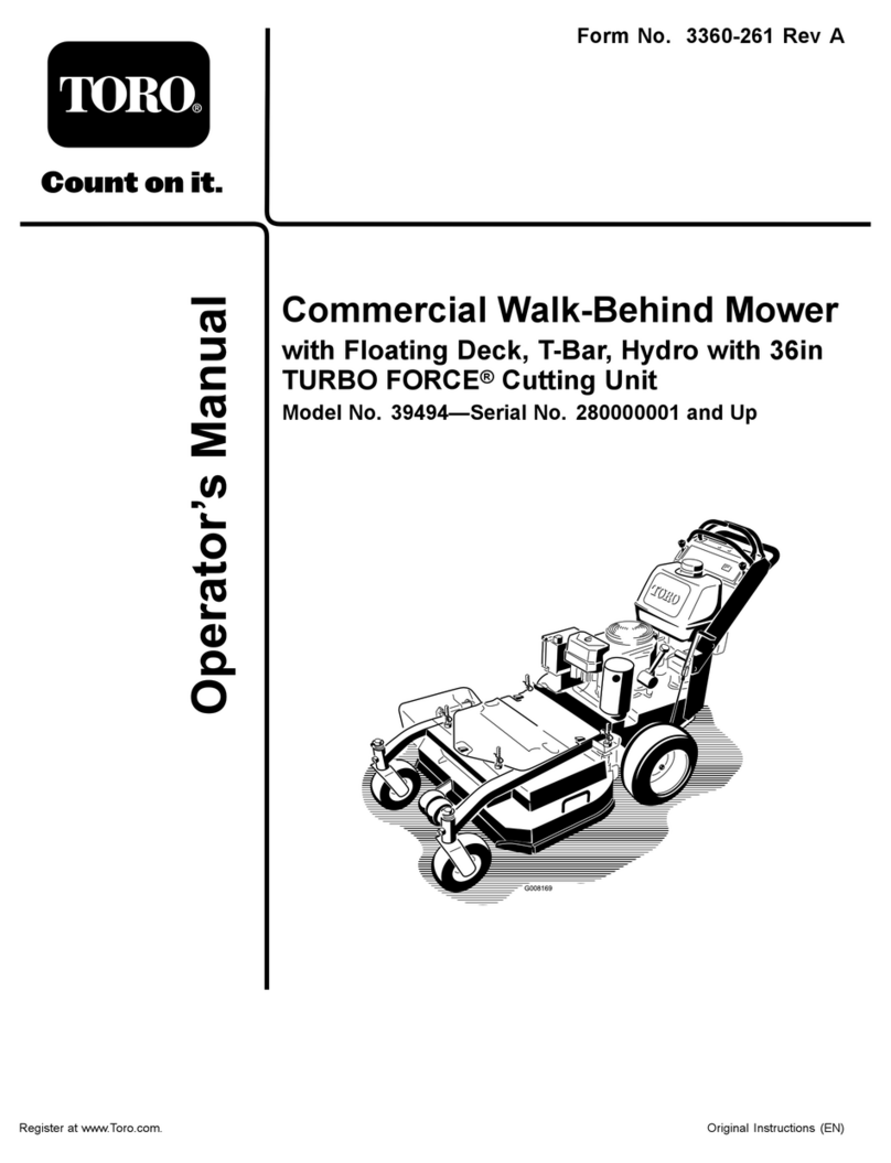
FORM NO. 3323-978 Rev B
The Toro Company  2000
OPERATOR'S
MANUAL
72” Flex DeckSide Discharge Mower
FOR GROUNDSMASTER300 SERIES TRACTION UNITS
MODEL NO. 30799 - 200000001 & UP
To ensure maximum safety, optimum performance,
and to gain knowledge of the product, it is essential
that you or any other operator of the machine read
and understand the contents of this manual before
the engine is ever started. Pay particular attention
to the SAFETY INSTRUCTIONS highlighted by this
symbol 
The safety alert symbol means CAUTION,
WARNING or DANGER  personal safety
instruction. Failure to comply with the instruction
may result in personal injury.

The Groundsmaster 300 Series Traction unit with a
72" Flex Deck Side Discharge Mower conforms to
the American National Standards Institute's for
Riding Mowers when weights are installed
according to chart on page 12.
2
FOREWORD
The 72" Flex Deck Side Discharge Mower has advanced concepts in engineering, design and safety; and if
maintained properly, will give excellent service.
Since this is a high-quality product, Toro is concerned about the future use of the machine and safety of the user.
Therefore, read this manual to familiarize yourself with proper set-up, operation and maintenance instructions. The
major sections of the manual are:
1. Safety Instructions 3. Before Operating 5. Lubrication
2. Set-up Instructions 4. Operation 6. Maintenance
Certain information in this manual is emphasized. DANGER, WARNING and CAUTION identify personal safety
related information. IMPORTANT identifies mechanical information demanding special attention. Be sure to read
this directive because it deals with the possibility of damaging a part or parts of the machine. NOTE identifies general
information worthy of special attention.
TABLE OF CONTENTS
Page Page
SAFETY INSTRUCTIONS 3-4. . . . . . . . . . . . . . . . . . .
SAFETY AND INSTRUCTION DECALS 5. . . . . . . . .
SPECIFICATIONS 6. . . . . . . . . . . . . . . . . . . . . . . . . . . .
LOOSE PARTS 6. . . . . . . . . . . . . . . . . . . . . . . . . . . . . . .
SET-UP INSTRUCTIONS 8-12. . . . . . . . . . . . . . . . .
Mount Hose Clamp 8. . . . . . . . . . . . . . . . . . . . . . . .
Grass Deflector 8. . . . . . . . . . . . . . . . . . . . . . . . . . . .
Mount Rear Castor Wheels 8. . . . . . . . . . . . . . . . .
Connect R.H. Push Arm to Cutting Unit 8. . . . . . .
Connect L.H. Push Arm to Cutting Unit 9. . . . . . .
Mount Front Lift Arm 10. . . . . . . . . . . . . . . . . . . . . .
Mount Rear Lift Bracket 10. . . . . . . . . . . . . . . . . . .
Install Drive Shaft to Traction Unit 11. . . . . . . . . . .
Install Lift Chains 11. . . . . . . . . . . . . . . . . . . . . . . . .
Adjust Counterbalance Spring 11. . . . . . . . . . . . .
Grease Cutting Unit 11. . . . . . . . . . . . . . . . . . . . . . .
Install Rear Weight 12. . . . . . . . . . . . . . . . . . . . . . . .
BEFORE OPERATING 13. . . . . . . . . . . . . . . . . . . . . . .
Check Lubricant in Gear Box 13. . . . . . . . . . . . . . .
Adjusting Height-of-Cut 13. . . . . . . . . . . . . . . . .
Check Tire Pressure 14. . . . . . . . . . . . . . . . . . . . . .
Adjusting Skid 14. . . . . . . . . . . . . . . . . . . . . . . . . . .
Adjusting Roller 14. . . . . . . . . . . . . . . . . . . . . . . . . .
OPERATING INSTRUCTIONS 15. . . . . . . . . . . . . . . . .
Grass Deflector 15. . . . . . . . . . . . . . . . . . . . . . . . . . .
Operating Tips 15. . . . . . . . . . . . . . . . . . . . . . . . . . .
LUBRICATION 16. . . . . . . . . . . . . . . . . . . . . . . . . . . . . .
Grease Bearings, Bushings and Gear Box 16. . .
MAINTENANCE 18-19. . . . . . . . . . . . . . . . . . . . . . . . .
Trouble Shooting 18. . . . . . . . . . . . . . . . . . . . . . . . .
Separating Cutting Unit from Traction Unit 19. . .
Mounting Cutting Unit to Traction Unit 19. . . . . . .
Adjusting Drive Belts 19. . . . . . . . . . . . . . . . . . . . . .
Replacing Drive Belts 20. . . . . . . . . . . . . . . . . . . . .
Servicing Front Bushings in Castor Arms 20. . . .
Servicing Castor Wheels and Bearings 20. . . . . .
Replacing Grass Deflector 21. . . . . . . . . . . . . . . . .
Removing Cutter Blades 21. . . . . . . . . . . . . . . . . . .
Inspecting and Sharpening Blades 22. . . . . . . . .
Correcting Cutting Unit Mismatch 23. . . . . . . . . . .
IDENTIFICATION AND ORDERING 23. . . . . . . . . . . .
WARRANTY Back Cover. . . . . . . . . . . . . . . . . . . . . . . . .
3
SAFETY INSTRUCTIONS
The safety alert symbol means
CAUTION, WARNING or DAN
GER  personal safety
instruction". Read and under
stand the instruction because
it has to do with safety. Failure to comply with
the instruction may result in personal injury.
Hazard control and accident prevention are
dependent upon the awareness, concern, and
proper training of the personnel involved in the
operation, transport, maintenance, and storage of
the machine. Improper use or maintenance of the
machine can result in injury or death. To reduce the
potential for injury or death, comply with the
following safety instructions.
WARNING: Engine exhaust contains carbon
monoxide which is an odorless, deadly poison. Carbon
monoxide is also known to the State of California to
cause birth defects. Do not run engine indoors or in an
enclosed area.
BEFORE OPERATING
1. Read and understand the contents of this
Operator's Manual before operating the machine.
Become familiar with all controls and know how to stop
quickly. A free replacement manual is available by
sending complete Model and Serial Number to:
The Toro Company
8111 Lyndale Avenue South
Minneapolis, Minnesota 55420-1196
2. Never allow children to operate the machine. Do
not allow adults to operate machine without proper
instruction. Only trained operators who have read this
manual should operate this machine.
3. Never operate the machine when under the
influence of drugs or alcohol.
4. Remove all debris or other objects that might be
picked up and thrown by the cutter blades. Keep all
bystanders away from the mowing area.
5. Keep all shields and safety devices in place. If a
shield, safety device or decal is illegible or damaged,
repair or replace it before operation is commenced.
Also tighten any loose nuts, bolts and screws to ensure
machine is in safe operating condition.
6. Do not operate machine while wearing sandals,
tennis shoes, sneakers or shorts. Also, do not wear
loose fitting clothing which could get caught in moving
parts. Always wear long pants and substantial shoes.
Wearing safety glasses, safety shoes and a helmet is
advisable and required by some local ordinances and
insurance regulations.
7. Check interlock switches daily for proper operation
(Refer To Section in Traction Unit Operator's Manual on
Checking Interlock Switches). Do not rely entirely on
safety switches shut off engine before getting off seat.
If a switch fails, replace it before operating the
machine. The interlock system is for your protection,
so do not bypass it. Replace all interlock switches
every two years. Interlock switches should be adjusted
so:
A. Engine cannot be started unless traction pedal
is released (neutral position) and PTO lever is
DISENGAGED (off position).
B. Engine stops if operator gets off seat when
traction pedal is depressed.
C. Engine stops if operator gets off seat when
PTO lever is ENGAGED (on position).
8. Fill fuel tank before starting the engine. Avoid
spilling any fuel. Since fuel is flammable, handle it
carefully.
A. Use an approved fuel container.
B. Do not fill tank while engine is hot or running.
C. Do not smoke while handling gasoline.
D. Fill fuel tank outdoors and up to about one inch
from top of the tank, not the filler neck.
E. Wipe up any spilled gasoline.
WHILE OPERATING
9. Do not run the engine in a confined area without
adequate ventilation. Exhaust fumes are hazardous
and could possibly be deadly.
10. Maximum seating capacity is one person. Never
carry passengers.
11. Sit on the seat when starting the engine and
operating the machine.
12. This product may exceed noise levels of 85 dB(A)
at the operator position. Ear protectors are
recommended for prolonged exposure to reduce the
potential of permanent hearing damage.
13. Before starting the engine:
A. Engage the parking brake.
B. Ensure traction pedal is in neutral and PTO is in
the OFF, disengaged position.
C. After engine is started, release parking brake
and keep foot off traction pedal. Machine must not
move. If movement is evident, the neutral return
mechanism is adjusted incorrectly; therefore, shut
engine off and adjust until machine does not move
when traction pedal is released.
14. Using the machine demands attention, and to
prevent loss of control:
A. Mow only in daylight or when there is good
artificial light.
B. Drive slowly and watch for holes or other
hidden hazards.
C. Do not drive close to a sand trap, ditch, creek
or other hazard.
4
SAFETY INSTRUCTIONS
D. Reduce speed when making sharp turns and
when turning on hillsides.
E. Avoid sudden starts and stops.
F. Before backing up, look to the rear and ensure
no one is behind the machine.
G. Watch out for traffic when near or crossing
roads. Always yield the right-of -way.
15. If engine stalls or machine loses headway and
cannot make it to the top of a slope, do not turn
machine around. Always back slowly straight down the
slope.
16. The grass deflector must always be installed and in
lowest position on the side discharge cutting unit.
Never operate mower without deflector or entire grass
collector. This product is designed to drive objects into
the ground where they lose energy quickly in grassy
areas. However, don't take an injury risk!! When a
person or pet appears unexpectedly in or near the
mowing area, STOP MOWING. Careless operation,
combined with terrain angles, ricochets, or improperly
positioned guards, can lead to thrown object injuries.
Do not resume mowing until area is cleared. If the
cutting unit discharge area ever plugs, shut engine off
before removing the obstruction.
17. Never raise the cutting unit while the blades are
rotating.
18. If the cutting blades strike a solid object or the
machine vibrates abnormally, disengage PTO, move
throttle to SLOW, set parking brake and shut engine off.
Remove key from switch to prevent possibility of
accidental starting. Check cutting unit and traction unit
for damage and malfunctioning parts. Repair any
damage before restarting the engine and operating the
cutting unit. Be sure blades are in good condition and
blade bolts are tight.
19. Cut grass slopes carefully. Do not start, stop, or
turn suddenly.
20. Do not touch engine or muffler while engine is
running or soon after it is stopped. These areas couId
be hot enough to cause a burn.
21. Before getting off the seat:
A. Move traction pedal to neutral position and
remove foot from pedal.
B. Set the parking brake and disengage the PTO.
C. Shut the engine off and remove the key from
the ignition switch. Wait for all movement to stop
before getting off the seat.
22. Lower the cutting unit to the ground and remove
key from ignition switch whenever machine is left
unattended.
23. This product may exceed noise levels of 85 dB(A)
at the operator position. Ear protectors are
recommended for prolonged exposure to reduce the
potential of permanent hearing damage.
MAINTENANCE
24. Remove key from ignition switch to prevent
accidental starting of the engine when servicing,
adjusting or storing the machine.
25. Perform only those maintenance instructions
described in this manual. If major repairs are ever
needed or assistance is desired, contact an Authorized
Toro Distributor.
26. To reduce potential fire hazard, keep the engine
free of excessive grease, grass, leaves and
accumulations of dirt.
27. Be sure machine is in safe operating condition by
keeping nuts, bolts and screws tight. Check the blade
mounting bolts and nuts frequently to be sure they are
tightened to specification.
28. Make sure all hydraulic line connectors are tight,
and all hydraulic hoses and lines are in good condition
before applying pressure to the system.
29. Keep body and hands away from pin hole leaks in
hydraulic lines that eject high pressure hydraulic fluid.
Use cardboard or paper to find hydraulic leaks.
Hydraulic fluid escaping under pressure can penetrate
skin and cause injury. Fluid accidentally injected into
the skin must be surgically removed within a few hours
by a doctor familiar with this form of injury or gangrene
may result.
30. Before disconnecting or performing any work on
the hydraulic system, all pressure in system must be
relieved by stopping engine and lowering cutting unit
to the ground.
31. If the engine must be running to perform a
maintenance adjustment, keep hands, feet, clothing
and other parts of the body away from the cutting unit
blades and other moving parts.
32. Do not overspeed the engine by changing
governor settings. To be sure of safety and accuracy,
have an Authorized TORO Distributor check maximum
engine speed with a tachometer.
33. Engine must be shut off before checking oil or
adding oil to the crankcase.
34. At the time of manufacture the cutting unit
conformed to safety standards in effect for riding
mowers. Therefore, to ensure optimum performance
and safety, always purchase genuine TORO
replacement parts and accessories to keep the Toro all
TORO. NEVER USE WILL-FIT" REPLACEMENT
PARTS AND ACCESSORIES MADE BY OTHER
MANUFACTURERS. Look for the TORO logo to ensure
genuineness. Using unapproved replacement parts
and accessories could void the warranty of The Toro
Company.

5
SAFETY AND INSTRUCTION DECALS
The following decals are installed on the machine. If any become damaged or illegible, replace it. The decal part
number is listed below and in your parts catalog. Replacements can be ordered from your Authorized Toro
Distributor.
ON LEFT CHAMBER COVER
(Part No. 93-3709 )
ON FRONT CENTER OF
EACH CHAMBER
(Part No. 100-8046)
ON FRONT NOSE OF EACH
CHAMBER
(Part No. 100-6582)
ON FRONT CENTER OF
EACH CHAMBER
(Part No. 100-6578)
LOCATED BY SPRINGS
(Part No. 93-6696)
ON LEFT SIDE OF GEAR BOX
(Part No. 93-6697)
NEAR REAR HANGER BRACKETS,
RIGHT CHAMBER
(Part No.100-8039 )
ON LEFT RIGHT SUPPORT
OF LEFT CHAMBER
(Part No. 93-7818)
NEAR DISCHARGE CHUTE
(Part No. 93-7824)
ON RIGHT REAR HANGER,
CENTER CHAMBER
(Part No. 100-8038)
ON REAR OF LEFT CHAMBER
(Part No. 93-7809)
ON FRONT OF LEFT ARM
ASSEMBLY
(Part No. 92-3035)
6
SPECIFICATIONS
Width of Cut: 72"
Configuration: Three blades, one blade center
section, and two 1 blade floating wings. Wings flex up
and down 12 degrees in a single plane perpendicular
to from center section.
Height of Cut: Adjustable front and rear, in .50 inch
increments from 1 to 4 inches.
Construction: 12-gauge steel, 5.25 inches deep,
welded construction and reinforced with 10-gauge
steel channels.
Blades: Three 25 inch long, .250 inch thick, heat
treated steel blades.
Cutter Drive: PTO driven gearbox with 1.26-1 spiral
bevel gears. One "B" section belt on center section.
One "B" section belt on each wing. Center section
tensioned through spring loaded idler. Wings
tensioned through adjustable fixed idler.
Spindles: Cast iron housing, 1-1/4 inch dia shaft with
welded blade retainer. Turning on two greaseable
tapered roller bearings. A positive splined connection
attaches pulley to spindle shaft.
Castor Wheels: Front: Four 8 inch pneumatic wheels
with greaseable roller bearings. Rear: Two 8 inch
pneumatic wheels with greaseable roller bearings (one
on each wing). Center section suspended from push
arms.
Anti Scalp: Anti-scalp cup (11 inch diameter) located
on each blade. One anti-scalp roller on rear of center
section. Adjustable skid on right wing.
Trimability: 34" uncut circle, 25" uncut circle with use
of individual wheel brakes.
Tip Speed: 15,000 ft./min. @ 3200 engine RPM.
Discharge: Left hand, side discharge (recycler kit
available).
Safety Certification: To meet, proposed ANSI
B71.4-1990 and 1999, safety specifications for power
lawn mowers, and CE requirements.
Belt Covers: Steel covers bolted down, meets CE
requirements.
Sound Levels: 90 dba @ operator ear.
Weight: 550 lbs.
Width: 83.5 in.
Options:
High Lift Blade: Part No. 23-2410
Height of cut spacers 1/4" Part No. 54-8810
Tire - Foam Filled 8" Part No. 93-5974
Specifications and design subject to change without notice.
7
LOOSE PARTS
NOTE: Use this chart as a checklist to ensure all parts have been received. Without these parts, total set-up cannot
be completed.
Hose Clamp 1
Hose Bracket 2 Install hose clamp
Capscrew 1/4-20 x 1" lg. 2
Nut 2
Push Arm Adapter 1
Push Arm Plate 1
Capscrew 3/8-16 x 2-3/4" lg. 4 Install right push arm adaptor
Flat Washer 4
Nut 4
Front Lift Arm 1
Lock Nut 2
Capscrew 1/2-13 x 3-1/2" lg. 2
Rear Lift Bracket 1
Square U-Bolt 1
U-Bolt 1
H.O.C. Chain 1 Install rear lift support
Clevis Pin 1
Hair Pin 1
Nut 6
Capscrew 3/8-16 x 7/8" lg. 4 Secure covers for C.E.
Operator's Manual 1 Read Before Operating Machine.
Parts Catalog 1
Registration Card 1 Fill Out And Return To Toro.
Description UseQty.
8
SET-UP INSTRUCTIONS
MOUNT HOSE CLAMP (Fig. 1 -2)
1. Using dimensions shown in figure 1, locate, mark
and drill (2) .280" dia. holes in traction unit platform.
Use caution when drilling as there are hoses and
cables under platform.
Figure 1
.75"
4.41"
12.75"
2. Secure hoses to under side of platform with clamp,
(2) brackets, capscrews and nuts. Position brackets to
fit contour of hoses and platform.
Figure 2
1
1. Clamp
2. Bracket (2)
2
GRASS DEFLECTOR (Fig. 3)
3. Remove shipping bands allowing deflector to be
lowered.
Defector is spring loaded in the down position
and will rotate downward, if not retrained,
when band is cut. If done improperly, personal
injury may occur.
WARNING
Figure 3
1. grass Deflector
1
MOUNT REAR CASTOR WHEELS (Fig. 4)
The rear castor wheels are shipped secured upside
down to deck brackets.
1. Remove capscrew and locknut securing front of
rear castor pivot to deck bracket.
Figure 4
1. Rear castor pivot arm
1
2. Turn pivot right side up and secure front of castor
pivot arm to front of deck bracket with capscrew and
locknut removed.
3. Align the pivot arm holes with selected
height-of-cut bracket holes in the deck frame, install
clevis pin and secure with hairpin cotter.
4. Repeat procedure on other castor wheel
assembly.
CONNECT RIGHT HAND PUSH ARM TO
CUTTING UNIT (Fig. 5- 6)
Note: Ball joints are shipped with traction unit.
1. Thread a jam nut fully onto ball joint.
2. Thread ball joint into push arm adapter until a
dimension of 2-3/8" from end of adapter to center of
ball joint is attained. Do not tighten jam nut.
9
SET-UP INSTRUCTIONS
Figure 5
1. Ball joint
2. Jam nut
3. Push arm adapter
1
32-3/8"
2
3. Remove (2) flange head capscrews and flange
nuts securing right hand ball joint mount to castor arm.
Remove ball joint mount from castor arm.
4. Install ball joint to right hand ball joint mount with a
castle nut and cotter pin (Fig. 6).
5. Loosely mount push arm adapter to bottom of right
push arm with a push arm bracket and (4) capscrews,
flat washers and flange head locknuts. Push arm
bracket to be positioned approximately 1" from end of
right push arm.
Note: Push arm plate to be positioned on top of push
arm. Push arm adapter is mounted to under side of
push arm.
6. Move cutting unit into position in front of traction
unit.
Figure 6
1. R.H. Push Arm
2. Push arm adapter
3. Push arm plate
4. Ball Joint Mount
1
2
3
4
Since the right hand push arm is spring loaded
to about 100 pounds, a helper is needed to
push the arm down. Sudden release of the
push arm could cause injury.
WARNING
7. Have a helper carefully push down on the right
push arm until holes in ball joint mount line up with
holes in castor arm. Immediately slide a 4 x 4 in. block
of wood between top of push arm and underside of
chassis.
8. Secure ball joint mount to castor arm with (2)
flange head capscrews and flange nuts previously
removed.
Note: Capscrew heads to be positioned on inside of
castor arm.
9. Tighten large jam nut securing ball joint to push
arm adapter (FIg. 5). When tightening jam nut, hold
ball joint straight to permit proper oscillation during
raising and lowering of cutting unit. Carefully remove
wood block holding push arm down.
CONNECT LEFT HAND PUSH ARM TO
CUTTING UNIT (Fig. 7- 8)
Since the left hand push arm is spring loaded
to about 150 pounds, a helper is needed to
push the arm down. Sudden release of the
push arm could cause injury.
WARNING
1. Thread a jam nut fully onto ball joint.
2. Thread ball joint into left push arm until a
dimension of 2-3/8" from end of push arm to center of
ball joint is attained. Do not tighten jam nut.
Figure 7
1. Ball joint
2. Jam nut
2. Left push arm
1
3
2-3/8"
2
10
SET-UP INSTRUCTIONS
3. Remove (2) flange head capscrews and flange
nuts securing left hand ball joint mount to castor arm.
Remove ball joint mount from castor arm.
4. Install ball joint to left hand ball joint mount with a
castle nut and cotter pin.
Figure 8
1. L.H. Push Arm
2. Ball joint
3. Ball Joint Mount
1
2
3
5. Have a helper carefully push down on the push
arm until holes in ball joint mount line up with holes in
castor arm. Immediately slide a 4 x 4 in. block of wood
between top of push arm and underside of chassis.
Make sure the wooden block does not slip out
accidentally. Sudden release of the push arm
could cause injury.
WARNING
6. Secure ball joint mount to castor arm with flange
head capscrews and flange nuts previously removed.
Note: Flange head capscrew heads to be positioned
on inside of castor arm.
7. Tighten large jam nut securing ball joint to push
arm. When tightening jam nut, hold ball joint straight to
permit proper oscillation during raising and lowering of
cutting unit. Carefully remove wood block holding
push arm down.
Note: Position deck so there is a 2" gap between
front of traction unit tires and rear of deck (Fig.).
Figure 9
2"
8. Tighten fasteners securing right push arm adapter
to right push arm.
MOUNT FRONT LIFT ARM (Fig. 10 & 11)
1. Remove rubber bumper from bottom of .traction
T-bar.
Figure 10
1. Traction T-bar
2. Rubber bumper
1
2
2. Slide front lift arm onto traction unit t-bar,
positioning as shown in figure 11.
3. Secure front lift arm to t-bar with with (2)
capscrews and locknuts.
Figure 11
1. Front lift arm
2. Traction unit T-bar
1
2
MOUNT REAR LIFT BRACKET (Fig. 12-)
1. Loosely mount rear lift bracket to right push arm
with square U-bolt, (2) nuts and flange nuts. Bracket
to be positioned on push arm so it is centered and
parallel to castor arm.
Figure 12
1. Lift bracket
2. Square u-bolt
3. U-bolt
1
2
3