Toro 30809 Groundsmaster 3500-G User manual

FormNo.3396-206RevA
Groundsmaster®3500-GRotary
Mower
ModelNo.30809—SerialNo.315000001andUp
Registeratwww.Toro.com.
OriginalInstructions(EN)*3396-206*A

WARNING
CALIFORNIA
Proposition65Warning
Thisproductcontainsachemicalorchemicals
knowntotheStateofCaliforniatocausecancer,
birthdefects,orreproductiveharm.
Theengineexhaustfromthisproduct
containschemicalsknowntotheStateof
Californiatocausecancer,birthdefects,
orotherreproductiveharm.
Important:Thisengineisnotequippedwithaspark
arrestermufer.ItisaviolationofCaliforniaPublic
ResourceCodeSection4442touseoroperatetheengine
onanyforest-covered,brush-covered,orgrass-covered
land.Otherstatesorfederalareasmayhavesimilarlaws.
Introduction
Thismachineisaride-on,rotary-bladelawnmowerintended
tobeusedbyprofessional,hiredoperatorsincommercial
applications.Itisprimarilydesignedforcuttinggrasson
well-maintainedlawnsinparks,golfcourses,sportselds,
andoncommercialgrounds.Itisnotdesignedforcutting
brush,mowinggrassandothergrowthalongsidehighways,
orforagriculturaluses.
Readthisinformationcarefullytolearnhowtooperateand
maintainyourproductproperlyandtoavoidinjuryand
productdamage.Youareresponsibleforoperatingthe
productproperlyandsafely.
YoumaycontactTorodirectlyatwww .Toro.comforproduct
andaccessoryinformation,helpndingadealer,ortoregister
yourproduct.
Wheneveryouneedservice,genuineToroparts,oradditional
information,contactanAuthorizedServiceDealerorToro
CustomerServiceandhavethemodelandserialnumbersof
yourproductready.Figure1identiesthelocationofthe
modelandserialnumbersontheproduct.Writethenumbers
inthespaceprovided.
1
Figure1
1.Modelandserialnumberlocation
ModelNo.
SerialNo.
Thismanualidentiespotentialhazardsandhassafety
messagesidentiedbythesafetyalertsymbol(Figure2),
whichsignalsahazardthatmaycauseseriousinjuryordeath
ifyoudonotfollowtherecommendedprecautions.
Figure2
1.Safetyalertsymbol
Thismanualuses2wordstohighlightinformation.
Importantcallsattentiontospecialmechanicalinformation
andNoteemphasizesgeneralinformationworthyofspecial
attention.
©2015—TheToro®Company
8111LyndaleAvenueSouth
Bloomington,MN554202
Contactusatwww.Toro.com.
PrintedintheUSA
AllRightsReserved

Contents
Safety...........................................................................4
SafeOperatingPractices...........................................4
SoundPowerLevel..................................................6
SoundPressureLevel...............................................6
VibrationLevel......................................................6
SafetyandInstructionalDecals.................................7
Setup...........................................................................11
1Activating,Charging,andConnectingthe
Battery..............................................................12
2CheckingtheAngleIndicator.................................13
3AdjustingtheLiftArms........................................13
4AdjustingtheCarrierFrame..................................14
5AdjustingtheHeightofCut...................................15
6CheckingtheMachinebeforeOperation..................16
7AdjustingtheOptionalRollerScraper
........................................................................16
8InstallingtheOptionalMulchingBafe
........................................................................16
ProductOverview.........................................................17
Controls...............................................................17
Specications........................................................19
Attachments/Accessories........................................19
Operation....................................................................19
ThinkSafetyFirst...................................................19
CheckingtheEngine-OilLevel.................................19
FillingtheFuelTank...............................................20
CheckingtheCoolingSystem...................................22
CheckingtheHydraulicSystem................................22
CheckingtheTirePressure......................................23
RearWheelBallast..................................................23
StartingandStoppingtheEngine..............................24
CheckingtheInterlockSystem.................................24
TowingtheTractionUnit.........................................24
StandardControlModule(SCM)..............................25
ChoosingAccessories.............................................27
SelectingaBlade.....................................................27
OperatingTips......................................................28
Maintenance.................................................................30
RecommendedMaintenanceSchedule(s)......................30
DailyMaintenanceChecklist....................................31
ServiceIntervalChart.............................................32
PremaintenanceProcedures........................................32
RemovingtheHood...............................................32
UsingtheCutting-UnitServiceLatch........................33
Lubrication...............................................................33
GreasingtheBearingsAndBushings.........................33
EngineMaintenance..................................................36
ServicingtheAirCleaner.........................................36
ChangingtheEngineOilandFilter...........................37
ReplacingtheSparkPlugs........................................37
FuelSystemMaintenance...........................................38
ReplacingtheFuel-PumpFilter................................38
ServicingtheFuelTank...........................................39
InspectingtheFuelLinesandConnections.................39
ElectricalSystemMaintenance....................................39
CaringfortheBattery..............................................39
Fuses....................................................................40
DriveSystemMaintenance.........................................40
TorquingtheWheelNuts........................................40
AdjustingtheTractionDriveforNeutral....................40
CoolingSystemMaintenance......................................41
CleaningtheEngineCoolingSystem.........................41
BrakeMaintenance....................................................42
AdjustingtheParkingBrake.....................................42
BeltMaintenance......................................................42
ServicingtheEngineBelts.......................................42
HydraulicSystemMaintenance....................................43
ChangingtheHydraulicFilter...................................43
ChangingtheHydraulicFluid...................................44
CheckingtheHydraulicLinesandHoses....................44
MaintainingtheCuttingUnit.......................................45
SeparatingtheCuttingUnitfromtheTraction
Unit..................................................................45
MountingtheCuttingUnitstotheTraction
Unit..................................................................45
ServicingtheBladePlane.........................................45
ServicingtheCutterBlade.......................................46
ServicingtheFrontRoller........................................47
Storage........................................................................49
StoringtheBattery..................................................49
PreparationforSeasonalStorage..............................49
3

Safety
ThismachinemeetsorexceedsANSIB71.4-2012
specicationswhenequippedwithrequiredweightas
listedinRearBallastsection.
Improperuseormaintenancebytheoperatoror
ownercanresultininjury.Toreducethepotential
forinjury,complywiththesesafetyinstructionsand
alwayspayattentiontothesafetyalertsymbol,which
meansCaution,Warning,orDanger—personalsafety
instruction.Failuretocomplywiththeinstructionmay
resultinpersonalinjuryordeath.
SafeOperatingPractices
ThefollowinginstructionsareadaptedfromANSIstandard
B71.4-2012.
Training
•ReadtheOperator'sManualandothertrainingmaterial.
Iftheoperator(s)ormechanic(s)cannotreadEnglishitis
theowner'sresponsibilitytoexplainthismaterialtothem.
•Becomefamiliarwiththesafeoperationoftheequipment,
operatorcontrols,andsafetysigns.
•Alloperatorsandmechanicsshouldbetrained.The
ownerisresponsiblefortrainingtheusers.
•Neverletchildrenoruntrainedpeopleoperateorservice
theequipment.Localregulationsmayrestricttheageof
theoperator.
•Theowner/usercanpreventandisresponsiblefor
accidentsorinjuriesoccurringtopeopleordamageto
property.
Preparation
•Evaluatetheterraintodeterminewhataccessoriesand
attachmentsareneededtoproperlyandsafelyperform
thejob.Onlyuseaccessoriesandattachmentsapproved
bythemanufacturer.
•Inspecttheareawheretheequipmentistobeusedand
removeallobjectssuchasrocks,toysandwirewhichcan
bethrownbythemachine.
•Checkthatoperator'spresencecontrols,safetyswitches
andshieldsareattachedandfunctioningproperly.Donot
operateunlesstheyarefunctioningproperly.
Operation
•Thisproductiscapableofamputatinghandsandfeet,and
throwingobjects.Alwaysfollowallsafetyinstructionsto
avoidseriousinjuryordeath.
•Useofthisproductforpurposesotherthanitsintended
usecouldprovedangeroustotheuserandbystanders.
•Donotoperatetheengineinaconnedspacewhere
dangerouscarbonmonoxideandotherexhaustgasses
cancollect.
•Onlyoperateingoodlight,keepingawayfromholesand
hiddenhazards.
•Besurealldrivesareinneutralandparkingbrakeis
engagedbeforestartingengine.Onlystartenginefrom
theoperator'sposition.
•Alwayswearsubstantial,slip-resistantfootwear,long
trousers,hardhat,safetyglasses,andhearingprotection
whilemowing.Longhair,looseclothing,orjewelrymay
gettangledinmovingparts.Donotoperatethemachine
whenbarefootorwearingopensandals.
•Slowdownanduseextracareonhillsides.Besureto
travelsidetosideonhillsides.Turfconditionscanaffect
themachine'sstability.Usecautionwhileoperatingnear
drop-offs.
•Slowdownandusecautionwhenmakingturnsandwhen
changingdirectionsonslopes.
•Neverraisedeckwiththebladesrunning.
•NeveroperatewiththePTOshield,orotherguardsnot
securelyinplace.Besureallinterlocksareattached,
adjustedproperly,andfunctioningproperly.
•Neveroperatewiththedischargedeectorraised,
removedoraltered,unlessusingagrasscatcher.
•Donotchangetheenginegovernorsettingoroverspeed
theengine.
•Beforeleavingtheoperator'spositionforanyreason
includingemptyingthecatchersoruncloggingthechute,
stoponlevelground,disengagedrives,engageparking
brake(ifprovided),shutoffengineandremovethekey
fromtheignition.
•Stopequipmentandinspectbladesafterstrikingobjects
orifanabnormalvibrationoccurs.Makenecessary
repairsbeforeresumingoperations.
•Lookbehindanddownbeforebackinguptobesureof
aclearpath.
•Keeppetsandbystandersaway.
•Slowdownandusecautionwhenmakingturnsand
crossingroadsandsidewalks.Stopbladesifnotmowing.
•Beawareofthemowerdischargedirectionanddonot
pointitatanyone.
•Donotoperatethemowerundertheinuenceofalcohol
ordrugs.
•Usecarewhenloadingorunloadingthemachineinto
orfromatrailerortruck.
•Usecarewhenapproachingblindcorners,shrubs,trees,
orotherobjectsthatmayobscurevision.
•Lightningcancausesevereinjuryordeath.Iflightning
isseenorthunderisheardinthearea,donotoperate
themachine;seekshelter.
•Knowhowtostopthemachineandenginequickly.
•Keephands,feet,andclothingawayfrommovingparts
andthecuttingunit.
4

•Checkthesafetyinterlockswitchesdailyforproper
operation.Ifaswitchshouldfail,replacetheswitch
beforeoperatingthemachine.
•Whenstartingtheengine,engagetheparkingbrake,put
thetractionpedalinneutral,anddisengagetheblade
drive.Aftertheenginestarts,releasetheparkingbrake
andkeepyourfootoffofthetractionpedal.Themachine
mustnotmove.Ifmovementisevident,refertothe
Maintenancesectionofthismanualtoadjustthetraction
drive.
•Useextremecautionwhenoperatingclosetosandtraps,
ditches,creeks,steephillsides,orotherhazards.
•Reducespeedwhenmakingsharpturns.
•Donotturnonhills.
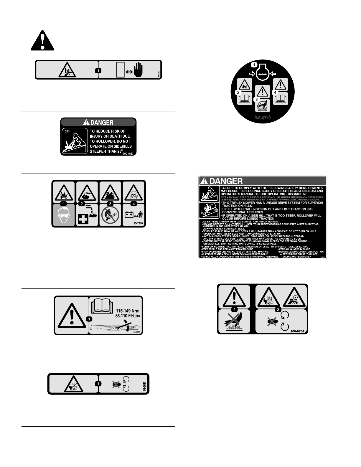
•Donotoperateonasidehillthatistoosteep.Arollover
mayoccurbeforelosingtraction.
•Theslopeangleatwhichthemachinewilltipisdependent
onmanyfactors.Amongthesearemowingconditions
suchaswetorundulatingterrain,speed(especiallyin
turns),positionofthecutting-units(withtheSidewinder),
tirepressure,andoperatorexperience.Atsidehillangles
of20degreesorless,theriskofarolloverislow .As
theslopeangleincreasestoarecommendedmaximum
limitof25degrees,theriskofarolloverincreasestoa
moderatelevel.Donotexceeda25degreesidehill
slopeanglebecausetheriskofarolloverandserious
injuryordeathisveryhigh.
•Forsteeringcontrol,lowerthecutting-unitswhengoing
downslopes.
•Avoidsuddenstopsandstarts.
•Usethereversepedalforbraking.
•Watchfortrafcwhennearorcrossingroads.Always
yieldtheright-of-way.
•Raisethecutting-unitswhendrivingfromoneworkarea
toanother.
•Donottouchtheengine,mufer,exhaustpipe,or
hydraulictankwhiletheengineisrunningorsoonafterit
hasstopped.Theseareascouldbehotenoughtocause
burns.
•Thismachineisnotdesignedorequippedforon-roaduse
andisaslow-movingvehicle.Ifyoumustcrossortravel
onapublicroad,youshouldbeawareofandcomplywith
localregulations,suchasrequiredlights,slowmoving
vehiclesigns,andreectors.
RolloverProtectionSystem(ROPS)-
UseandMaintenance
•TheROPSisanintegralandeffectivesafetydevice.
•DonotremovetheROPS.
•Becertainthattheseatbeltcanbereleasedquicklyin
theeventofanemergency.
•Checkcarefullyforoverheadclearances(i.e.branches,
doorways,electricalwires)beforedrivingunderany
objectsanddonotcontactthem.
•AnyalterationstoaROPSmustbeapprovedbythe
manufacturer.
•KeeptheROPSinsafeoperatingcondition.Thoroughly
inspectfordamageperiodicallyandalwayskeepall
mountingfastenerstight.
•ReplaceadamagedROPS.Donotrepairorrevise.
SafeHandlingofFuels
•Toavoidpersonalinjuryorpropertydamage,use
extremecareinhandlinggasoline.Gasolineisextremely
ammableandthevaporsareexplosive.
•Extinguishallcigarettes,cigars,pipes,andothersources
ofignition.
•Useonlyanapprovedfuelcontainer.
•Neverremovefuelcaporaddfuelwiththeengine
running.
•Allowenginetocoolbeforerefueling.
•Neverrefuelthemachineindoors.
•Neverstorethemachineorfuelcontainerwherethereis
anopename,spark,orpilotlightsuchasonawater
heateroronotherappliances.
•Neverllcontainersinsideavehicleoronatruckor
trailerbedwithaplasticliner.Alwaysplacecontainerson
thegroundawayfromyourvehiclebeforelling.
•Removeequipmentfromthetruckortrailerandrefuelit
ontheground.Ifthisisnotpossible,thenrefuelsuch
equipmentwithaportablecontainer,ratherthanfroma
fueldispensernozzle.
•Keepthenozzleincontactwiththerimofthefueltank
orcontaineropeningatalltimesuntilfuelingiscomplete.
Donotuseanozzlelock-opendevice.
•Fillthefueltankuntillevelis6to13mm(1/4to1/2
inch)belowthebottomofthellerneck.Donotoverll.
•Iffuelisspilledonclothing,changeclothingimmediately.
•Neveroverllfueltank.Replacefuelcapandtighten
securely.
MaintenanceandStorage
•Disengagedrives,setparkingbrake,stopengineand
removekeyordisconnectsparkplugwire.Waitforall
movementtostopbeforeadjusting,cleaning,orrepairing.
•Cleangrassanddebrisfromcuttingunit,drives,mufers,
andenginetohelppreventres.Cleanupoilorfuel
spillage.
•Letenginecoolbeforestoringanddonotstorenear
ame.
•Shutofffuelwhilestoringortransporting.Donotstore
fuelnearamesordrainindoors.
•Parkmachineonlevelground.Setparkingbrake.
•Neverallowuntrainedpersonneltoservicemachine.
•Usejackstandstosupportcomponentswhenrequired.
5

•Carefullyreleasepressurefromcomponentswithstored
energy.
•Disconnectthebatteryorremovesparkplugwirebefore
makinganyrepairs.Disconnectthenegativeterminalrst
andthepositivelast.Reconnectthepositiverstand
negativelast.
•Usecarewhencheckingblades.Wraptheblade(s)or
weargloves,andusecautionwhenservicingthem.Only
replaceblades.Neverstraightenorweldthem.
•Keephandsandfeetawayfrommovingparts.Ifpossible,
donotmakeadjustmentswiththeenginerunning.
•Keepallpartsingoodworkingconditionandallhardware
tightened.Replacewornordamageddecals.
•Keepyourbodyandhandsawayfrompin-holeleaksor
nozzlesthatejecthydraulicuidunderhighpressure.
Ifuidisinjectedintotheskin,itmustbesurgically
removedwithinafewhours,byadoctorfamiliarwiththis
formofinjuryorgangrenemayresult.
•Hydraulicuidescapingunderpressurecanhave
sufcientforcetopenetratetheskinandcauseserious
injury.Usepaperorcardboard,notyourhands,tosearch
forleaks.
•Beforedisconnectingorperforminganyworkon
thehydraulicsystem,allpressureinthesystemmust
berelievedbystoppingtheengineandloweringthe
cutting-unitstotheground.
•Makesurethatallhydraulic-lineconnectorsaretightand
allhydraulichosesandlinesareingoodconditionbefore
applyingpressuretothesystem.
•Iftheenginemustberunningtoperformamaintenance
adjustment,keephands,feet,clothing,andanypartsof
thebodyawayfromthecutting-units,attachments,and
anymovingparts.Keepeveryoneaway.
•Donotoverspeedtheenginebychanginggovernor
settings.Toensuresafetyandaccuracy,havean
AuthorizedToroDistributorcheckthemaximumengine
speedwithatachometer.
•Theenginemustbeshutoffbeforecheckingtheoilor
addingoiltothecrankcase.
•Ifmajorrepairsareeverneededorifassistanceisdesired,
contactanAuthorizedToroDistributor.
•Toensureoptimumperformanceandcontinuedsafety
certicationofthemachine,useonlygenuineToro
replacementpartsandaccessories.Replacementparts
andaccessoriesmadebyothermanufacturerscouldbe
dangerous,andsuchusecouldvoidtheproductwarranty.
Hauling
•Usecarewhenloadingorunloadingthemachineintoa
trailerortruck.
•Usefullwidthrampsforloadingmachineintotraileror
truck.
•Tiethemachinedownsecurelyusingstraps,chains,cable,
orropes.Bothfrontandrearstrapsshouldbedirected
downandoutwardfromthemachine.
SoundPowerLevel
Thisunithasaguaranteedsoundpowerlevelof106dBA,
whichincludesanUncertaintyValue(K)of1dBA.
Soundpowerlevelwasdeterminedaccordingtothe
proceduresoutlinedinISO11094.
SoundPressureLevel
Thisunithasasoundpressurelevelattheoperator’searof93
dBA,whichincludesanUncertaintyValue(K)of1dBA.
Soundpressurelevelwasdeterminedaccordingtothe
proceduresoutlinedinEN836.
VibrationLevel
Hand-Arm
Measuredvibrationlevelforrighthand=0.5m/s2
Measuredvibrationlevelforlefthand=0.7m/s2
UncertaintyValue(K)=0.5m/s2
Measuredvaluesweredeterminedaccordingtotheprocedures
outlinedinEN836.
WholeBody
Measuredvibrationlevel=0.44m/s2
UncertaintyValue(K)=0.5m/s2
Measuredvaluesweredeterminedaccordingtotheprocedures
outlinedinEN836.
6

SafetyandInstructionalDecals
Safetydecalsandinstructionsareeasilyvisibletotheoperatorandarelocatednearanyareaofpotential
danger.Replaceanydecalthatisdamagedorlost.
94-3353
1.Crushinghazardofhand—keepyourhandsasafedistance
away.
100-4837
93-7276
1.Explosionhazard—weareyeprotection.
2.Causticliquid/chemicalburnhazard—toperformrstaid,
ushwithwater.
3.Firehazard—nore,openames,orsmoking.
4.Poisonhazard—keepchildrenasafedistancefromthe
battery.
93-7818
1.Warning—readtheOperator'sManualforinstructionson
torquingthebladebolt/nutto85-110ft-lb(115-149N-m).
93-6681
1.Cutting/dismemberment—hazard,fan-stayawayfrom
movingparts.
106-6755
1.Enginecoolantunder
pressure.
3.Warning—donottouchthe
hotsurface.
2.Explosionhazard—read
theOperator'sManual.
4.Warning—readthe
Operator'sManual.
104-0484
106-6754
1.Warning—donottouchthehotsurface.
2.Cutting/dismembermenthazard,fanandentanglement
hazard,belt—stayawayfrommovingparts.
7

BatterySymbols
Someorallofthesesymbolsareonyourbattery
1.Explosionhazard6.Keepbystandersasafe
distancefromthebattery.
2.Nore,opename,or
smoking.
7.Weareyeprotection;
explosivegasescan
causeblindnessandother
injuries
3.Causticliquid/chemical
burnhazard
8.Batteryacidcancause
blindnessorsevereburns.
4.Weareyeprotection9.Flusheyesimmediately
withwaterandgetmedical
helpfast.
5.ReadtheOperator's
Manual.
10.Containslead;donot
discard.
99-3444
99-3444
1.Transportspeed—fast2.Mowingspeed—slow
117-4764
1.Thrownobjecthazard—keepbystandersasafedistance
fromthemachine.
2.Cuttinghazardofhand,mowerblade—stayawayfrom
movingparts,keepallguardsandshieldsinplace.
3.Cuttinghazardoffoot,mowerblade—stayawayfrom
movingparts,keepallguardsandshieldsinplace.
107–1971
106-9290
1.Inputs5.Inseat9.Outputs13.Start
2.Notactive6.PowerT ake-off(PTO)10.PowerT ake-off(PTO)14.Power
3.High-temperature
shutdown
7.ParkingbrakeOff11.Start
4.High-temperaturewarning8.Neutral12.EnergizetoRun(ETR)
8

121–3531
1.EngagePTO6.Moveleft11.ReadtheOperator’sManualfor
informationonstoppingtheengine—
1)Disengagethereel;2)Movethekey
totheenginestopposition;3)Remove
thekeyfromtheignition;4)Engage
theparkingbrake.
2.DisengagePTO7.Lock12.Fast
3.Lowercuttingunit8.Engine—stop13.Slow
4.Moveright9.Engine—run
5.Raisecuttingunit10.Engine—start
104-1086
1.Heightofcut
9

121–3533
1.ReadtheOperator’sManualforinformationonmaintenance.
10

Setup
LooseParts
Usethechartbelowtoverifythatallpartshavebeenshipped.
ProcedureDescriptionQty.Use
1Nopartsrequired–Activate,charge,andconnectthe
battery.
2Nopartsrequired–Checktheangleindicator.
3Nopartsrequired–Adjusttheliftarms.
4Nopartsrequired–Adjustthecarrierframe.
5Nopartsrequired–Adjusttheheightofcut.
6Nopartsrequired–Checktheuidlevels.
7Nopartsrequired–Adjusttheoptionalrollerscraper.
8Nopartsrequired–Installtheoptionalmulchingbafe.
MediaandAdditionalParts
DescriptionQty.Use
Ignitionkeys2Starttheengine.
Operator'sManual1
EngineOperator'sManual1Readbeforeoperatingthemachine.
PartsCatalog1Usetolookupandorderparts.
Operatorvideo1Viewbeforeoperatingthemachine.
Note:Determinetheleftandrightsidesofthemachinefromthenormaloperatingposition.
11

1
Activating,Charging,and
ConnectingtheBattery
NoPartsRequired
Procedure
WARNING
CALIFORNIA
Proposition65Warning
Batteryposts,terminals,andrelated
accessoriescontainleadandleadcompounds,
chemicalsknowntotheStateofCalifornia
tocausecancerandreproductiveharm.
W ash hands after handling .
Note:Ifthebatteryisnotlledwithelectrolyteoractivated,
bulkelectrolytewith1.260specicgravitymustbepurchased
fromalocalbatterysupplyoutletandaddedtothebattery.
DANGER
Batteryelectrolytecontainssulfuricacidwhichisa
deadlypoisonandcausessevereburns.
•Donotdrinkelectrolyteandavoidcontactwith
skin,eyes,orclothing.Wearsafetyglassesto
shieldyoureyesandrubberglovestoprotect
yourhands.
•Fillthebatterywherecleanwaterisalways
availableforushingtheskin.
1.Openthehood.
2.Removethebatterycover(Figure3).
Figure3
1.Batterycover
3.Removethellercapsfromthebatteryandslowlyll
eachcelluntilelectrolyteisjustabovetheplates.
4.Installthellercapsandconnecta3to4ampbattery
chargertothebatteryposts.Chargethebatteryata
rateof3to4amperesfor4to8hours.
WARNING
Chargingthebatteryproducesgassesthatcan
explode.
•Keepsparksandamesawayfrombattery.
•Neversmokenearthebattery.
5.Whenthebatteryischarged,disconnectthecharger
fromtheelectricaloutletandbatteryposts.
6.Removethellercaps.Slowlyaddelectrolytetoeach
celluntilthelevelisuptothellring.Installtheller
caps.
Important:Donotoverllthebattery.Electrolyte
willoverowontootherpartsofthemachineand
severecorrosionanddeteriorationwillresult.
7.Installthepositivecable(red)tothepositive(+)
terminalandthenegativecable(black)tothenegative
(–)terminalofthebatteryandsecurethemwithbolts
andnuts(Figure4).Makesurethatthepositive(+)
terminalisallofthewayontothepostandthecable
ispositionedsnugtothebattery.Thecablemustnot
contactthebatterycover.
WARNING
Incorrectbatterycableroutingcoulddamage
thetractionunitandcablescausingsparks.
Sparkscancausethebatterygassesto
explode,resultinginpersonalinjury.
•Alwaysdisconnectthenegative(black)
batterycablebeforedisconnectingthe
positive(red)cable.
•Alwaysconnectthepositive(red)battery
cablebeforeconnectingthenegative
(black)cable.
12

Figure4
1.Positive(+)batterycable2.Negative(–)batterycable
Important:Ifthebatteryiseverremoved,make
surethatthebatteryclampboltsareinstalledwith
theboltheadspositionedonthebottomsideand
thenutsonthetopside.Iftheclampboltsare
reversed,theymayinterferewiththehydraulic
tubeswhenshiftingthecutting-units.
8.CoatbothbatteryconnectionswithGrafo112X(skin
over)grease,ToroPartNo.505-47,petroleumjelly,or
lightgreasetopreventcorrosion.
9.Slidetherubberbootoverthepositiveterminalto
preventapossibleshortfromoccurring.
10.Installthebatterycover.
2
CheckingtheAngleIndicator
NoPartsRequired
Procedure
DANGER
Donotoperatethemachineonsidehillssteeper
than25ºtoreduceriskofinjuryordeathdueto
rollover.
1.Parkthemachineonaat,levelsurface.
2.Verifythatthemachineislevelbyplacingahandheld
inclinometer(suppliedwiththemachine)ontheframe
crossrail,bythefueltank(Figure5).Theinclinometer
shouldreadzerodegreeswhenviewedfromthe
operator’sposition.
Figure5
1.Angleindicator
3.Iftheinclinometerdoesnotreadzerodegrees,move
themachinetoalocationwhereazerodegreereading
isobtained.Theangleindicator,mountedonthe
machine,shouldnowreadzerodegreesaswell.
4.Iftheangleindicatordoesnotreadzerodegrees,loosen
the2screwsandnutssecuringtheangleindicatorto
themountingbracket,adjusttheindicatortoobtaina
zerodegreereading,andtightenthebolts.
3
AdjustingtheLiftArms
NoPartsRequired
Procedure
1.Starttheengine,raisethecutting-units,andcheckto
ensurethattheclearancebetweeneachliftarmandthe
oor-platebracketis5to8mm(0.18to0.32inch)as
showninFigure6.
Figure6
cutting-unitsremovedforclarity
1.Liftarm3.Clearance
2.Floor-platebracket
13

Iftheclearanceisnotinthisrange,adjustitasfollows:
A.Backoffthestopbolts(Figure7).
Figure7
1.Stopbolt3.Clearance
2.Liftarm
B.Backoffthejamnutonthecylinder(Figure8).
Figure8
1.Frontcylinder2.Jamnut
C.Removethepinfromtherodendandrotatethe
clevis.
D.Installthepinandchecktheclearance.Repeat
theprocedureifrequired.
E.Tightentheclevis-jamnut.
2.Checktomakesurethattheclearancebetweeneachlift
armandstopboltis0.13to1.02mm(0.005to0.040
inch)asshowninFigure7.Iftheclearanceisnotin
thisrange,adjustthestopboltstoattainclearance.
3.Starttheengine,raisethecuttingunits,andcheckto
makesurethattheclearancebetweenthewearstrap
onthetopoftherearcuttingunitwearbarandthe
bumperstrapis0.51to2.54mm(0.02to0.10inch)as
showninFigure9.
Figure9
1.Wearbar2.Bumperstrap
Iftheclearanceisnotinthisrange,adjusttherear
cylinderasfollows:
Note:Iftherearliftarmclunksduringtransport,
clearancecanbereduced.
A.Lowerthecutting-unitsandbackoffthejamnut
onthecylinder(Figure10).
Figure10
1.Rearcylinder2.Adjustingnut
B.Graspthecylinderrodclosetothenutwitha
pliersandrag,androtatetherod.
C.Raisethecutting-unitsandchecktheclearance.
Repeattheprocedureifrequired.
D.Tightentheclevis-jamnut.
Important:Lackofclearanceatthefrontstopsorrear
wearbarcoulddamagetheliftarms.
4
AdjustingtheCarrierFrame
NoPartsRequired
AdjustingtheFrontCuttingUnit
Thefrontandrearcuttingunitsrequiredifferentmounting
positions.Thefrontcuttingunithas2mountingpositions
dependingonwhatheightofcutanddegreeofrotationyou
desire.
14

1.Foraheightofcutinthe2to7.6cm(3/4to3inch)
range,mountthefrontcarrierframesinthelower,
frontmountingholes(Figure11).
Note:Thispermitsmoreuptravelofthecuttingunit
relativetothetractionunitwhenapproachingquick
uphillchangesinterrain.Itdoeshoweverlimitthe
clearanceofthechambertothecarrierwhencresting
sharpknolls.
Figure11
1.Upper,frontmountinghole3.Rearmountinghole
2.Lower,frontmountinghole
2.Foraheightofcutinthe6.3to10cm(2-1/2to4inch)
range,mountthefront,carrierframesintheupper,
frontmountingholes(Figure11).
Note:Thisincreasesthechamber-to-carrierclearance
duetothehigherpositionofthecuttingchamber,but
willcausethecuttingunittoreachtheirmaximumup
travelsooner.
AdjustingtheRear,CuttingUnit
Thefrontandrear,cuttingunitsrequiredifferentmounting
positions.Therearcuttingunithasonemountingposition
forproperalignmentwiththesidewinder-underframe.
Forallheightsofcut,mounttherearcuttingunitintherear
mountingholes(Figure11).
5
AdjustingtheHeightofCut
NoPartsRequired
Procedure
Important:Thiscuttingunitoftencutsapproximately
6mm(1/4inch)lowerthanareel-cuttingunitwiththe
samebenchsetting.Itmaybenecessarytohavethe
rotary-cuttingunitbenchset6mm(1/4inch)abovethat
ofareel-cuttingunitinthesamearea.
Important:Accesstotherear,cuttingunitsisgreatly
improvedbyremovingthecuttingunitfromthetraction
unit.IftheunitisequippedwithaSidewinder®,
sidewindthecuttingunitstotheright,removetherear
cuttingunit,andslideitouttotherightside.
1.Lowerthecuttingunittotheground,stoptheengine,
andremovethekeyfromtheignition.
2.Loosentheboltsecuringeachheightofcutbracketto
theheightofcutplate(frontandeachside)asshown
inFigure12.
3.Beginningwithfrontadjustment,removethebolt.
Figure12
1.Heightofcutbracket3.Spacer
2.Heightofcutplate
4.Whilesupportingthechamber,removethespacer
(Figure13).
5.Movethechambertothedesiredheightofcutand
installaspacerintothedesignatedheightofcuthole
andslot(Figure13).
Figure13
6.Positionthetappedplateinlinewiththespacer.
7.Hand-tightenthebolts.
8.Repeatsteps4-7foreachsideadjustment.
9.Tightenall3boltsto41N-m(30ft-lb).Alwaystighten
thefrontboltrst.
15

Note:Adjustmentsofmorethan3.8cm(1-1/2inch)
mayrequiretemporaryassemblytoanintermediate
heighttopreventbinding.
6
CheckingtheMachinebefore
Operation
NoPartsRequired
Procedure
Performthefollowingcheckbeforeoperation:
•CheckingtheEngine-OilLevel(page19)
•CheckingtheCoolingSystem(page22)
•CheckingtheHydraulicSystem(page22)
•CheckingtheTirePressure(page23)
•TorquingtheWheelNuts(page40)
7
AdjustingtheOptionalRoller
Scraper
NoPartsRequired
Procedure
Theoptionalrear-rollerscraperisdesignedtoworkbest
whenthereisanevengapof0.5to1mm(0.020–0.040inch)
betweenthescraperandroller.
1.Loosenthegreasettingandthemountingscrew
(Figure14).
G01 1346
1
2
3
Figure14
1.Rollerscraper3.Greasetting
2.Mountingscrew
2.Slidethescraperupordownuntilagapof0.5to1
mm(0.020to0.040inch)isachievedbetweentherod
andtheroller.
3.Securethegreasettingandscrewto41N-m(30ft-lb)
inanalternatingsequence.
8
InstallingtheOptional
MulchingBafe
NoPartsRequired
Procedure
1.Thoroughlycleandebrisfromthemountingholeson
therearandleft,sidewallsofthechamber.
2.Installthemulchingbafeintherearopeningand
secureitwith5ange-headbolts(Figure15).
G01 1347
1
Figure15
1.Mulchingbafe
3.Verifythatmulchingbafedoesnotinterferewith
thetipofthebladeanddoesnotprotrudeinsidethe
surfaceoftherear,chamberwall.
WARNING
Donotusethehigh-liftbladewiththe
mulchingbafe.Thebladecouldbreak,
resultinginpersonalinjuryordeath.
16

ProductOverview
Controls
Figure16
1.Forward-tractionpedal4.Tilt-steeringlever
2.Reverse-tractionpedal5.Indicatorslot
3.Mow/transportslide6.Angleindicator
TractionPedals
Presstheforward-tractionpedal(Figure16)tomoveforward.
Pressthereverse-tractionpedal(Figure16)tomovebackward
ortoassistinstoppingwhenmovingforward.Tostopthe
tractionunit,movethepedalto,orallowittomoveto,the
neutralposition.
Mow/TransportSlide
UsingyourheeltomovetheMow/Transportslide(Figure
16)tothelefttotransport,andtotherighttomow.The
cutting-unitswillonlyoperateintheMowposition.
Note:Themowingspeedofthemachineissetatthefactory
to9.7km/h(6mph).Themowingspeedcanbeincreasedor
decreasedbyadjustingthespeed-stopscrew(Figure17).
Figure17
1.Speed-stopscrew
Tilt-SteeringLever
Pullthetilt-steeringlever(Figure16)backtotiltthesteering
wheeltothedesiredposition.Pushtheleverforwardtolock
thesteeringwheelintoposition.
IndicatorSlot
Theslotintheoperatorplatform(Figure16)indicateswhen
thecutting-unitsareinthecenterposition.
AngleIndicator
Theangleindicator(Figure16)indicatestheside-hillangleof
themachineindegrees.
IgnitionSwitch
Usetheignitionswitch(Figure18)isusedtostartandstop
theengine.The3positionsoftheswitchare;Off,On,and
Start.RotatethekeytotheStartpositiontostarttheengine.
Releasethekeywhentheenginestarts.Thekeyautomatically
movestotheOnpositionwhenyoureleaseit.Toshutthe
engineoff,rotatethekeytotheOffposition.Removethe
keyfromtheignitiontopreventsomeonefromstartingthe
machineunintentionally.
g021539
Figure18
1.Throttle7.PTOswitch
2.Hourmeter8.Cutting-unitshiftlever
3.Temperaturelight9.Ignitionswitch
4.Oilpressurelight10.Parkingbrake
5.Checkenginelight11.Liftleverlock
6.Alternatorlight
Throttle
Movethethrottle(Figure18)forwardtoincreasetheengine
speedandrearwardtodecreasetheenginespeed.
PTOSwitch
ThePTOswitch(Figure18)has2positions:Out(start)and
In(stop).PullthePTOswitchouttoengagethecutting-unit
blades.Pushtheswitchintodisengagethecutting-unitblades.
17

HourMeter
Thehourmeter(Figure18)indicatesthetotalhoursof
machineoperation.Thehourmeterstartstofunction
wheneverthekeyswitchisintheOnposition.
Cutting-UnitLever
Tolowerthecuttingunitstotheground,movethe
cutting-unitlever(Figure18)forward.Thecuttingunitswill
notdropunlesstheengineisrunning.Toraisethecutting
units,pulltheleverrearwardtotheRaiseposition.
Note:Theleverdoesnothavetobeheldintheforward
positionwhilethecuttingunitsarelowered.
Movethelevertotherightorleft,tomovethecuttingunits
totherightorleft.Thisshouldonlybedonewhenthe
cuttingunitsareraisedoriftheyareonthegroundandthe
machineismoving.
DANGER
Shiftthecuttingunitstotheuphillsideofthe
machinewhenonthesideofahill.
Usingthecuttingunitsonthedownhillsideofthe
machinecandecreasestability.Thiscouldcause
arollover,whichmayresultinpersonalinjuryor
death.
Coolant-TemperatureLight
Thecoolant-temperaturelight(Figure18)willturnonifthe
coolanttemperatureraisesaboveasetlevel.Theenginewill
stopifthecoolanttemperatureraisesanother10°F.
Oil-PressureLight
Theoil-pressurelight(Figure18)willturnoniftheoil
pressuredropsbelowasetlevel.
AlternatorLight
Checkorrepairthechargingsystemifthealternatorlight
turnsonwhentheengineisrunning(Figure18).
Check-EngineLight
Checkorrepairtheengineifthecheck-enginelightturnson
whentheengineisrunning(Figure18).RefertotheService
Manualforpossiblecauses.
ParkingBrake
Engagetheparkingbrakewhenevertheengineisshutoff
(Figure18).Pulluponthelevertoengagetheparkingbrake.
Note:Theenginewillstopifyoupressthetractionpedal
withtheparkingbrakeengaged.
Lift-LeverLock
Movethelift-leverlock(Figure18)rearwardtopreventthe
cuttingunitsfromdropping.
FuelGauge
Thefuelgauge(Figure19)indicatestheamountoffuelin
thefueltank.
g021400 2
1
Figure19
1.Seat-locklever2.Fuelgauge
AdjustingtheSeatForwardor
Backward
Movethelever(Figure19)onthesideoftheseatoutward
andslidetheseattothedesiredposition.Releasethelever
tolocktheseatintoposition.
18

Specications
Note:Specicationsanddesignaresubjecttochange
withoutnotice.
OverallWidth182cm(71.8inch)
WidthofCut173cm(68inch)
Length295cm(116inch)
HeighttotopofROPS180cm(70.8inch)
Wheelbase149cm(58.5inch)
Trackwidth145cm(57inch)
Groundclearance15.3cm(6inch)
Weightwithcuttingunits963kg(2,124lb)
CuttingDeck
Length86.4cm(34inch)
Width86.4cm(34inch)
Height24.4cm(9.6inch)
tocarriermount
26.7cm(10–1/2inch)
at3/4inchheightofcut
34.9cm(13–3/4inch)at4
inchesheightofcut
Weight88kg(195lb)
Attachments/Accessories
Tobestprotectyourinvestmentandmaintainoptimal
performanceofyourToroequipment,countonTorogenuine
parts.Whenitcomestoreliability,Torodeliversreplacement
partsdesignedtotheexactengineeringspecicationofour
equipment.Forpeaceofmind,insistonTorogenuineparts.
Operation
Note:Determinetheleftandrightsidesofthemachine
fromthenormaloperatingposition.
ThinkSafetyFirst
Carefullyreadallsafetyinstructionsandsymbolsinthe
safetysection.Knowingthisinformationcouldhelpyouor
bystandersavoidinjury.
DANGER
Operatingonwetgrassorsteepslopescancause
slidingandlossofcontrol.
Wheelsdroppingoveredgescancauserollovers,
whichmayresultinseriousinjury,death,or
drowning.
Usetheseatbelt.
Readandfollowtherolloverprotectioninstructions
andwarnings.
Toavoidlossofcontrolandpossibilityofrollover:
•Donotoperateneardrop-offsornearwater.
•Donotoperateonslopesgreaterthan25º.
•Reducespeedanduseextremecautionon
slopes.
•Avoidsuddenturnsorrapidspeedchanges.
CAUTION
Thismachineproducessoundlevelsthatcancause
hearinglossthroughextendedperiodsofexposure.
Wearhearingprotectionwhenoperatingthis
machine.
Theuseofprotectiveequipmentforeyes,ears,hands,feet,
andheadisrecommended.
G009027
12
Figure20
1.Wearsafetyglasses.2.Wearhearingprotection.
CheckingtheEngine-OilLevel
ServiceInterval:Beforeeachuseordaily
19

Theengineisshippedwithoilinthecrankcase;however,the
oillevelmustbecheckedbeforeandaftertheengineisrst
started.
Crankcasecapacityisapproximately3.3L(3.5USqt)with
thelter.
Note:ToroPremiumEngineoilisavailablefromyour
distributorineither15W-40or10W-30viscosity.Seethe
partscatalogforpartnumbers.
Note:Thebesttimetochecktheengineoiliswhenthe
engineiscoolbeforeithasbeenstartedfortheday.Ifithas
alreadybeenrun,allowtheoiltodrainbackdowntothe
sumpforatleast10minutesbeforechecking.Iftheoillevelis
atorbelowtheAddmarkonthedipstick,addoiltobringthe
oilleveltotheFullmark.Donotoverll.Iftheoillevelis
betweentheFullandAddmarks,additionaloilisnotrequired.
Theengineusesanyhigh-quality10W-30detergentoilhaving
theAmericanPetroleumInstitute(API)serviceclassication
SJ,SK,SL,SM,orhigher.Chooseaviscosityaccordingto
thetableinFigure21.
G016095
Figure21
1.Positionthemachineonalevelsurfaceandopenthe
hood.
2.Removethedipstick(Figure22)andwipeitwitha
cleanrag.Insertthedipstickintothetubeandmake
surethatitisseatedfully.Removedipstickandcheck
thelevel-of-the-oil.
g021401
1
2
Figure22
1.Dipstick2.Fillercap
3.Iftheoillevelislow,removethellercap(Figure22)
andaddenoughoiltoraisethelevel-of-the-oiltothe
Fullmarkonthedipstick.
Note:Whenaddingoil,removedipsticktoallow
properventing.Pouroilslowlyandcheckthe
level-of-the-oiloftenduringthisprocess.Donot
overll.
Important:Whenaddingengineoilorllingoil,
theremustbeclearancebetweentheoillldevice
andtheoilllholeinthevalvecoverasshownin
Figure23.Thisclearanceisnecessarytopermit
ventingwhenlling,whichpreventsoilfrom
overrunningintothebreather.
Figure23
1.Noteclearance
4.Installthedipstickrmlyinplace.
5.Installtheoil-llcapandclosethehood.
FillingtheFuelTank
•Fueltankcapacity:38L(10USgallons)
•RecommendedFuel:
–Forbestresults,useonlyclean,fresh(lessthan30
daysold),unleadedgasolinewithanoctaneratingof
87orhigher((R+M)/2ratingmethod).
–Ethanol:Gasolinewithupto10%ethanol(gasohol)
or15%MTBE(methyltertiarybutylether)by
volumeisacceptable.EthanolandMTBEarenot
thesame.Gasolinewith15%ethanol(E15)by
volumeisnotapprovedforuse.Neverusegasoline
thatcontainsmorethan10%ethanolbyvolume,
suchasE15(contains15%ethanol),E20(contains
20%ethanol),orE85(containsupto85%ethanol).
Usingunapprovedgasolinemaycauseperformance
problemsand/orenginedamagewhichmaynotbe
coveredunderwarranty.
20
Other manuals for 30809 Groundsmaster 3500-G
2
Table of contents
Other Toro Lawn Mower manuals

Toro
Toro 02835 User manual

Toro
Toro 74433 User manual

Toro
Toro Reelmaster 5100-D User manual

Toro
Toro Emotion 43 Series User manual

Toro
Toro Recycler 21356 User manual

Toro
Toro 31598N User manual

Toro
Toro Titan Z4800 User manual

Toro
Toro 72980 User manual

Toro
Toro 22189TE User manual

Toro
Toro 74997 User manual

Toro
Toro Super Recycler User manual

Toro
Toro 22197 User manual

Toro
Toro 74702 User manual

Toro
Toro Z Master 4000 Series User manual

Toro
Toro 22291 User manual

Toro
Toro LT-F3000 User manual

Toro
Toro TimeCutter User manual

Toro
Toro 74248 User manual

Toro
Toro 78216 User manual

Toro
Toro Z Master 74250 User manual