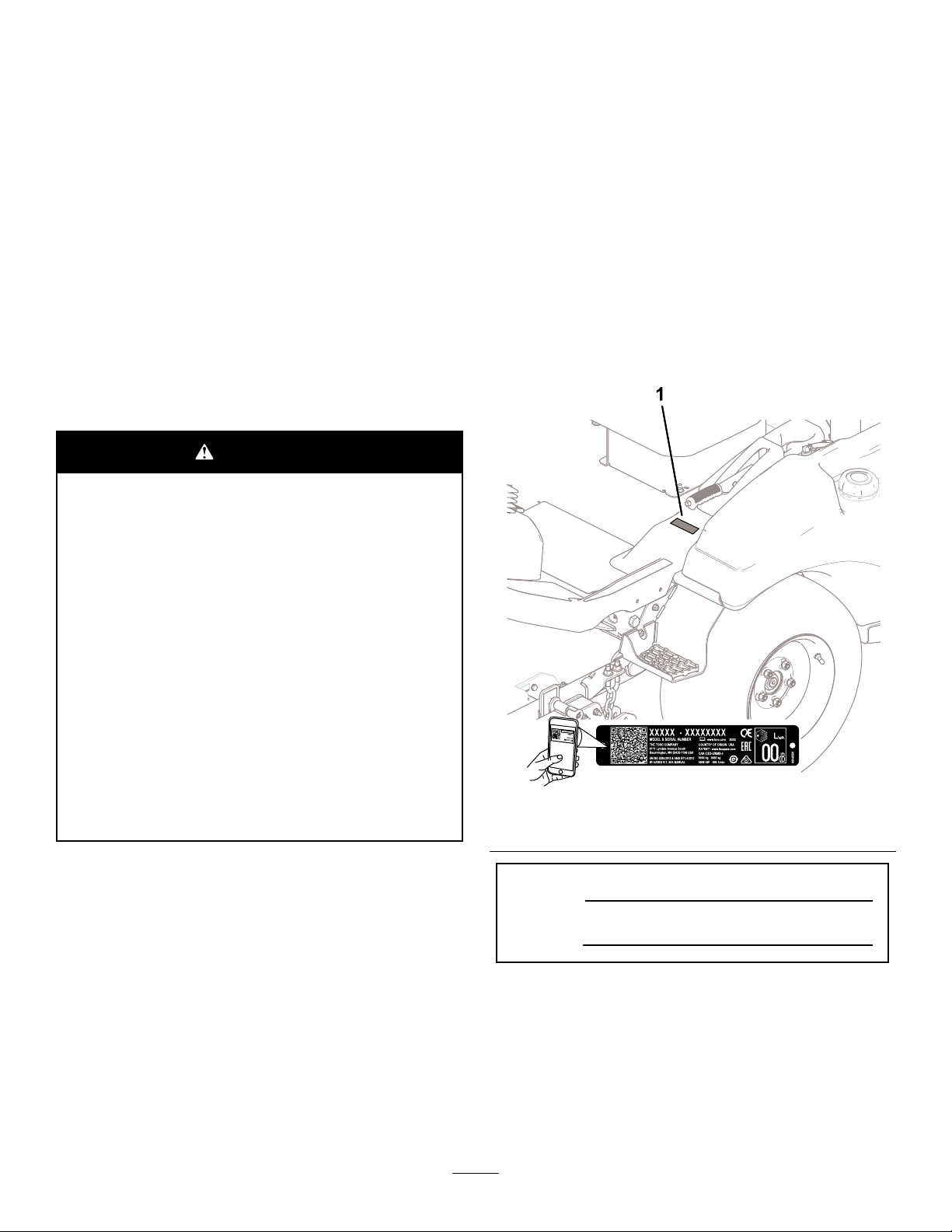
Toro 31900A User manual

Form No. 3466-395 Rev A
Groundsmaster
®
3300, 3310, and
3200 2-Wheel or 4-Wheel Drive
T raction Unit
Model No. 31900A —Serial No. 400000000 and Up
Model No. 31901A —Serial No. 400000000 and Up
Model No. 31907A —Serial No. 400000000 and Up
Model No. 31909A —Serial No. 400000000 and Up
Register at www .T oro.com.
Original Instructions (EN)
*3466-395*

Models 31900A and 31901A comply with all relevant
European directives; for details, please see the
separate product specic Declaration of Conformity
(DOC) sheet.
Models 31907A and 31909A do not comply with
relevant European directives.
It is a violation of California Public Resource Code
Section 4442 or 4443 to use or operate the engine on
any forest-covered, brush-covered, or grass-covered
land unless the engine is equipped with a spark
arrester , as dened in Section 4442, maintained in
ef fective working order or the engine is constructed,
equipped, and maintained for the prevention of re.
The enclosed engine owner's manual is supplied
for information regarding the US Environmental
Protection Agency (EP A) and the California Emission
Control Regulation of emission systems, maintenance,
and warranty . Replacements may be ordered through
the engine manufacturer .
W ARNING
CALIFORNIA
Proposition 65 W arning
Diesel engine exhaust and some of its
constituents are known to the State of
California to cause cancer , birth defects,
and other reproductive harm.
Battery posts, terminals, and related
accessories contain lead and lead
compounds, chemicals known to
the State of California to cause
cancer and reproductive harm. W ash
hands after handling.
Use of this product may cause exposure
to chemicals known to the State of
California to cause cancer , birth defects,
or other reproductive harm.
Introduction
This machine is a ride-on, multi-purpose machine
intended to be used by professional, hired operators
in commercial applications. It is primarily designed for
maintaining grass on well-maintained lawns in parks,
sports elds, and on commercial grounds. Using this
product for purposes other than its intended use could
prove dangerous to you and bystanders.
Read this information carefully to learn how to operate
and maintain your product properly and to avoid
injury and product damage. Y ou are responsible for
operating the product properly and safely .
V isit www .T oro.com for product safety and operation
training materials, accessory information, help nding
a dealer , or to register your product.
Whenever you need service, genuine T oro parts, or
additional information, contact an Authorized Service
Dealer or T oro Customer Service and have the model
and serial numbers of your product ready . Figure 1
identies the location of the model and serial numbers
on the product. W rite the numbers in the space
provided.
Important: W ith your mobile device, you can
scan the QR code on the serial number decal (if
equipped) to access warranty , parts, and other
product information.
g299536
Figure 1
Model No.
Serial No.
This manual identies potential hazards and has
safety messages identied by the safety-alert symbol
(Figure 2 ), which signals a hazard that may cause
serious injury or death if you do not follow the
recommended precautions.
© 2023—The T oro® Company
81 1 1 L yndale A venue South
Bloomington, MN 55420
2
Contact us at www .T oro.com.
Printed in the USA
All Rights Reserved

g000502
Figure 2
Safety-alert symbol
This manual uses 2 words to highlight information.
Important calls attention to special mechanical
information and Note emphasizes general information
worthy of special attention.
Contents
Safety . . . . . . . . . . . . . . . . . . . . . . . . . . . . . . . . . . . . . . . . . . . . . . . . . . . . . . . . . . . . . . . . . . . . . . . 4
General Safety . . . . . . . . . . . . . . . . . . . . . . . . . . . . . . . . . . . . . . . . . . . . . . . . . . . 4
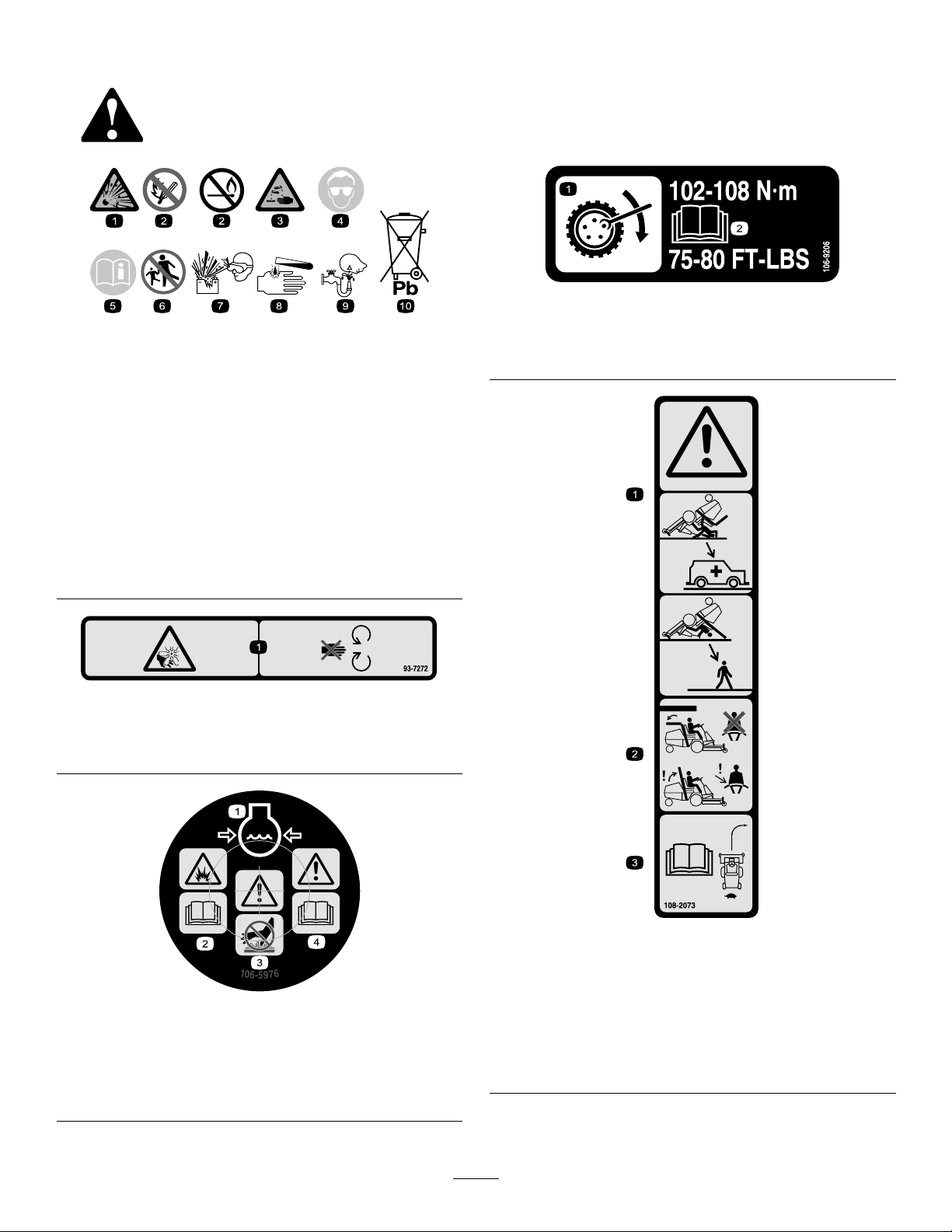
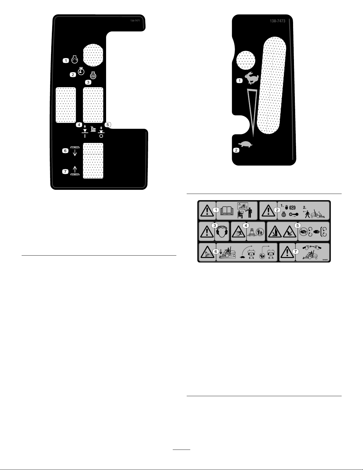
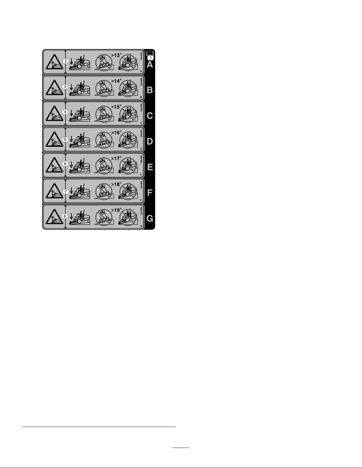
Safety and Instructional Decals . . . . . . . . . . . . . . . . . . . . . . . . . . 5
Setup . . . . . . . . . . . . . . . . . . . . . . . . . . . . . . . . . . . . . . . . . . . . . . . . . . . . . . . . . . . . . . . . . . . . . . . 1 1
1 Removing the Machine from the Shipping
Container . . . . . . . . . . . . . . . . . . . . . . . . . . . . . . . . . . . . . . . . . . . . . . . . . . . . . . 12
2 Installing the Rear T ires . . . . . . . . . . . . . . . . . . . . . . . . . . . . . . . . . 12
3 Removing the Front T ires . . . . . . . . . . . . . . . . . . . . . . . . . . . . . . . 13
4 Installing the Lift-Arm Assembly . . . . . . . . . . . . . . . . . . . . . 13
5 Installing the Front T ires . . . . . . . . . . . . . . . . . . . . . . . . . . . . . . . . . 15
6 Installing the T ie-Down Bracket . . . . . . . . . . . . . . . . . . . . . . 15
7 Installing the Seat . . . . . . . . . . . . . . . . . . . . . . . . . . . . . . . . . . . . . . . . . . 16
8 Installing the Steering Wheel . . . . . . . . . . . . . . . . . . . . . . . . . . 16
9 Installing the Sound Decal . . . . . . . . . . . . . . . . . . . . . . . . . . . . . . 17
10 Installing the Bumper . . . . . . . . . . . . . . . . . . . . . . . . . . . . . . . . . . . 17
1 1 Adjusting the Roll-Bar Position . . . . . . . . . . . . . . . . . . . . . 18
12 Connecting the Battery . . . . . . . . . . . . . . . . . . . . . . . . . . . . . . . . 19
13 Installing the Attachment . . . . . . . . . . . . . . . . . . . . . . . . . . . . . . 19
14 Checking the Fluid Levels . . . . . . . . . . . . . . . . . . . . . . . . . . . . 20
15 Checking the T ire Pressure . . . . . . . . . . . . . . . . . . . . . . . . . . 20
16 Installing the CE Kit . . . . . . . . . . . . . . . . . . . . . . . . . . . . . . . . . . . . . . 20
17 Adding Rear W eight . . . . . . . . . . . . . . . . . . . . . . . . . . . . . . . . . . . . . 21
18 Adjusting the W eight T ransfer of the
Attachment . . . . . . . . . . . . . . . . . . . . . . . . . . . . . . . . . . . . . . . . . . . . . . . . . . . . 27
Product Overview . . . . . . . . . . . . . . . . . . . . . . . . . . . . . . . . . . . . . . . . . . . . . . . . . . . 28
Controls . . . . . . . . . . . . . . . . . . . . . . . . . . . . . . . . . . . . . . . . . . . . . . . . . . . . . . . . . . . 29
Console . . . . . . . . . . . . . . . . . . . . . . . . . . . . . . . . . . . . . . . . . . . . . . . . . . . . . . . . . 30
Cab Controls . . . . . . . . . . . . . . . . . . . . . . . . . . . . . . . . . . . . . . . . . . . . . . . . . 32
Specications . . . . . . . . . . . . . . . . . . . . . . . . . . . . . . . . . . . . . . . . . . . . . . . . . . 33
Width Specications . . . . . . . . . . . . . . . . . . . . . . . . . . . . . . . . . . . . . . . . . 34
Attachments/Accessories . . . . . . . . . . . . . . . . . . . . . . . . . . . . . . . . . 34
Before Operation . . . . . . . . . . . . . . . . . . . . . . . . . . . . . . . . . . . . . . . . . . . . . . . . . 35
Before Operation Safety . . . . . . . . . . . . . . . . . . . . . . . . . . . . . . . . . . . 35
Checking the Machine Daily . . . . . . . . . . . . . . . . . . . . . . . . . . . . . 35
Checking the T ire Air Pressure . . . . . . . . . . . . . . . . . . . . . . . . . . 35
Adding Fuel . . . . . . . . . . . . . . . . . . . . . . . . . . . . . . . . . . . . . . . . . . . . . . . . . . . . . . 36
Checking the Safety-Interlock System . . . . . . . . . . . . . . 37
Adjusting the Roll Bar . . . . . . . . . . . . . . . . . . . . . . . . . . . . . . . . . . . . . . . 37
Understanding the Display-Screen
Information . . . . . . . . . . . . . . . . . . . . . . . . . . . . . . . . . . . . . . . . . . . . . . . . . . . . 39
During Operation . . . . . . . . . . . . . . . . . . . . . . . . . . . . . . . . . . . . . . . . . . . . . . . . . 41
During Operation Safety . . . . . . . . . . . . . . . . . . . . . . . . . . . . . . . . . . . 41
Starting the Engine . . . . . . . . . . . . . . . . . . . . . . . . . . . . . . . . . . . . . . . . . . . 42
Resetting the PT O Function . . . . . . . . . . . . . . . . . . . . . . . . . . . . . . 42
Understanding T urnaround Mode . . . . . . . . . . . . . . . . . . . . . 43
Shutting Of f the Engine . . . . . . . . . . . . . . . . . . . . . . . . . . . . . . . . . . . . . 43
After Operation . . . . . . . . . . . . . . . . . . . . . . . . . . . . . . . . . . . . . . . . . . . . . . . . . . . . 43
After Operation Safety . . . . . . . . . . . . . . . . . . . . . . . . . . . . . . . . . . . . . . 43
Servicing the Cutting Unit . . . . . . . . . . . . . . . . . . . . . . . . . . . . . . . . . 43
T owing the Machine . . . . . . . . . . . . . . . . . . . . . . . . . . . . . . . . . . . . . . . . . . 45
Hauling the Machine . . . . . . . . . . . . . . . . . . . . . . . . . . . . . . . . . . . . . . . . . 46
Maintenance . . . . . . . . . . . . . . . . . . . . . . . . . . . . . . . . . . . . . . . . . . . . . . . . . . . . . . . . . . . 47
Maintenance Safety . . . . . . . . . . . . . . . . . . . . . . . . . . . . . . . . . . . . . . . . . . 47
Recommended Maintenance Schedule(s) . . . . . . . . . . . 47
Daily Maintenance Checklist . . . . . . . . . . . . . . . . . . . . . . . . . . . . . 48
Pre-Maintenance Procedures . . . . . . . . . . . . . . . . . . . . . . . . . . . . . . 49
Raising the Machine . . . . . . . . . . . . . . . . . . . . . . . . . . . . . . . . . . . . . . . . . 49
Raising the Hood . . . . . . . . . . . . . . . . . . . . . . . . . . . . . . . . . . . . . . . . . . . . . . 50
Lubrication . . . . . . . . . . . . . . . . . . . . . . . . . . . . . . . . . . . . . . . . . . . . . . . . . . . . . . . . . . 51
Greasing the Bearings and Bushings . . . . . . . . . . . . . . . . 51
Engine Maintenance . . . . . . . . . . . . . . . . . . . . . . . . . . . . . . . . . . . . . . . . . . . 53
Engine Safety . . . . . . . . . . . . . . . . . . . . . . . . . . . . . . . . . . . . . . . . . . . . . . . . . . . 53
Servicing the Engine Oil . . . . . . . . . . . . . . . . . . . . . . . . . . . . . . . . . . . . 53
Servicing the Air Cleaner . . . . . . . . . . . . . . . . . . . . . . . . . . . . . . . . . . 55
Fuel System Maintenance . . . . . . . . . . . . . . . . . . . . . . . . . . . . . . . . . . . 56
Draining W ater from the Fuel/W ater
Separator . . . . . . . . . . . . . . . . . . . . . . . . . . . . . . . . . . . . . . . . . . . . . . . . . . . . . . 56
Servicing the Fuel/W ater Separator
...................................................................... 56
Servicing the Fuel Filter . . . . . . . . . . . . . . . . . . . . . . . . . . . . . . . . . . . . 57
Cleaning the Fuel T ank . . . . . . . . . . . . . . . . . . . . . . . . . . . . . . . . . . . . . 58
Inspecting the Fuel Lines and
Connections . . . . . . . . . . . . . . . . . . . . . . . . . . . . . . . . . . . . . . . . . . . . . . . . . . 58
Electrical System Maintenance . . . . . . . . . . . . . . . . . . . . . . . . . . . 58
Electrical System Safety . . . . . . . . . . . . . . . . . . . . . . . . . . . . . . . . . . . 58
Accessing the Battery . . . . . . . . . . . . . . . . . . . . . . . . . . . . . . . . . . . . . . . 58
Disconnecting the Battery . . . . . . . . . . . . . . . . . . . . . . . . . . . . . . . . . 59
Connecting the Battery . . . . . . . . . . . . . . . . . . . . . . . . . . . . . . . . . . . . . 59
Removing or Installing the Battery . . . . . . . . . . . . . . . . . . . . 60
Checking the Battery Condition . . . . . . . . . . . . . . . . . . . . . . . . . 60
Locating the Fuses . . . . . . . . . . . . . . . . . . . . . . . . . . . . . . . . . . . . . . . . . . . 60
Drive System Maintenance . . . . . . . . . . . . . . . . . . . . . . . . . . . . . . . . . . 62
T orquing the Wheel-Lug Nuts . . . . . . . . . . . . . . . . . . . . . . . . . . . 62
Aligning the PT O Driveshaft . . . . . . . . . . . . . . . . . . . . . . . . . . . . . . 62
Cooling System Maintenance . . . . . . . . . . . . . . . . . . . . . . . . . . . . . . 63
Cooling System Safety . . . . . . . . . . . . . . . . . . . . . . . . . . . . . . . . . . . . . 63
Coolant Specication . . . . . . . . . . . . . . . . . . . . . . . . . . . . . . . . . . . . . . . . 63
Checking the Cooling System and Coolant
Level . . . . . . . . . . . . . . . . . . . . . . . . . . . . . . . . . . . . . . . . . . . . . . . . . . . . . . . . . . . . . 63
Checking the Hood-Air-Intake Screen . . . . . . . . . . . . . . . 64
Checking the Cooling Fins . . . . . . . . . . . . . . . . . . . . . . . . . . . . . . . . 64
Inspecting the Cooling-System Hoses . . . . . . . . . . . . . . 64
Brake Maintenance . . . . . . . . . . . . . . . . . . . . . . . . . . . . . . . . . . . . . . . . . . . . . 65
Checking and Adjusting the Parking
Brake ............................................................ 65
Belt Maintenance . . . . . . . . . . . . . . . . . . . . . . . . . . . . . . . . . . . . . . . . . . . . . . . . 66
Checking the Alternator-Belt T ension . . . . . . . . . . . . . . . . 66
Servicing the T raction Belt . . . . . . . . . . . . . . . . . . . . . . . . . . . . . . . . 66
Controls System Maintenance . . . . . . . . . . . . . . . . . . . . . . . . . . . . . 67
Adjusting the PT O-Clutch Gap . . . . . . . . . . . . . . . . . . . . . . . . . . 67
3

Adjusting the T raction-Pedal Stop . . . . . . . . . . . . . . . . . . . . . 67
Hydraulic System Maintenance . . . . . . . . . . . . . . . . . . . . . . . . . . . 69
Hydraulic System Safety . . . . . . . . . . . . . . . . . . . . . . . . . . . . . . . . . . . 69
Hydraulic Fluid Specications . . . . . . . . . . . . . . . . . . . . . . . . . . . 69
Checking the Hydraulic-Fluid Level . . . . . . . . . . . . . . . . . . . 69
Changing the Hydraulic Fluid and
Filters . . . . . . . . . . . . . . . . . . . . . . . . . . . . . . . . . . . . . . . . . . . . . . . . . . . . . . . . . . . . 70
Checking the Hydraulic Lines and
Hoses . . . . . . . . . . . . . . . . . . . . . . . . . . . . . . . . . . . . . . . . . . . . . . . . . . . . . . . . . . . . 71
Cab Maintenance . . . . . . . . . . . . . . . . . . . . . . . . . . . . . . . . . . . . . . . . . . . . . . . . . 72
Cleaning the Cab . . . . . . . . . . . . . . . . . . . . . . . . . . . . . . . . . . . . . . . . . . . . . . 72
Cleaning the Cab Air Filters . . . . . . . . . . . . . . . . . . . . . . . . . . . . . . 72
Cleaning the Cab-Condenser Filter . . . . . . . . . . . . . . . . . . . 72
Replacing the Dome Light . . . . . . . . . . . . . . . . . . . . . . . . . . . . . . . . . 73
Filling the Windshield-Wiper-Fluid
Reservoir . . . . . . . . . . . . . . . . . . . . . . . . . . . . . . . . . . . . . . . . . . . . . . . . . . . . . . 73
Storage . . . . . . . . . . . . . . . . . . . . . . . . . . . . . . . . . . . . . . . . . . . . . . . . . . . . . . . . . . . . . . . . . . . 74
Storage Safety . . . . . . . . . . . . . . . . . . . . . . . . . . . . . . . . . . . . . . . . . . . . . . . . . . 74
Preparing the Machine . . . . . . . . . . . . . . . . . . . . . . . . . . . . . . . . . . . . . . 74
Safety
General Safety
This product is capable of amputating hands and
feet and of throwing objects. Always follow all safety
instructions to avoid serious personal injury .
•Read and understand the contents of this
Operator ’ s Manual before starting the engine.
•Use your full attention while operating the
machine. Do not engage in any activity that
causes distractions; otherwise, injury or property
damage may occur .
•Do not operate the machine without all guards
and other safety protective devices in place and
functioning properly on the machine.
•Keep your hands and feet away from rotating
parts. Keep clear of the discharge opening.
•Keep bystanders and children out of the operating
area. Never allow children to operate the machine.
•Shut of f the engine, remove the key , and wait
for all movement to stop before you leave the
operator ’ s position. Allow the machine to cool
before adjusting, servicing, cleaning, or storing it.
Improperly using or maintaining this machine can
result in injury . T o reduce the potential for injury ,
comply with these safety instructions and always
pay attention to the safety-alert symbol , which
means Caution, W arning, or Danger—personal safety
instruction. Failure to comply with these instructions
may result in personal injury or death.
4

Safety and Instructional Decals
Safety decals and instructions are easily visible to the operator and are located near any area
of potential danger . Replace any decal that is damaged or missing.
decalbatterysymbols
Battery Symbols
Some or all of these symbols are on your battery .
1. Explosion hazard 6. Keep bystanders away .
2. No re, open ames, or
smoking
7. W ear eye
protection—explosive
gases can cause blindness
and other injuries.
3. Caustic liquid/chemical
burn hazard
8. Battery acid can cause
severe burns.
4. W ear eye protection. 9. Flush eyes immediately
with water and get medical
help fast.
5. Read the Operator ’ s
Manual .
10. Contains lead; do not
discard.
decal93-7272
93-7272
1. Cutting/dismemberment hazard; fan—stay away from
moving parts.
decal106-5976
106-5976
1. Engine coolant under
pressure
3. W arning—do not touch the
hot surface.
2. Explosion hazard—read
the Operator's Manual .
4. W arning—read the
Operator's Manual .
decal106-9206
106-9206
1. Wheel torque specications
2. Read the Operator's Manual .
decal108-2073
108-2073
1. W arning—there is no rollover protection when the roll bar is
down.
2. T o avoid injury or death from a rollover accident, keep the
roll bar in the raised and locked position and wear the seat
belt. Lower the roll bar only when absolutely necessary; do
not wear the seat belt when the roll bar is down.
3. Read the Operator's Manual ; drive slowly and carefully .
5

decal1 15-8155
1 15-8155
1. W arning—read the Operator's Manual , do not prime or use
starting uid.
decal125-9688
125-9688
1. Of f 3. On
2. Windshield wipers
4. Spray windshield washer
uid.
decal127-0392
127-0392
1. W arning—stay away from hot surfaces.
decal132-1316
132-1316
1. Entanglement hazard, belt—keep away from moving parts.
decal133-8062
133-8062
decal138-2765
138-2765
1. Of f
3. Fixed speed—low
2. Intermittent windshield
wiper speed
4. Fixed speed—high
6

decal138-7471
138-7471
1. Engine—start 5. Push down to disengage
the cutting blade.
2. Engine—run 6. Deck—lower
3. Engine—stop 7. Deck—raise
4. Lift up to engage the
cutting blade.
decal138-7473
138-7473
1. Fast
2. Slow
decal139-6215
139-6215
1. W arning—read the
Operator ’ s Manual ; all
operators should be
trained before operating
the machine.
5. Cutting/dismemberment
hazard of hand or
foot—stay away from
moving parts; keep all
guards and shields in
place.
2. W arning—engage the
parking brake, shut of f
the engine, and remove
the key before leaving the
machine.
6. T ipping hazard—lower the
cutting units when moving
downhill; drive slowly
when turning; do not turn
sharply while traveling
fast.
3. W arning—wear hearing
protection.
7. W arning—always wear a
seatbelt when operating
the machine.
4. Thrown object
hazard—keep bystanders
away .
7

decal139-6224
139-6224
1. Parking
brake—disengaged
2. Parking brake—engaged
decal139-6304
139-6304
1. Entanglement hazard—read the Operator ’ s Manual ; stay
away from moving parts; keep all guards and shields in
place.
decal140-1460
140-1460
1. T o move the machine
forward, press forward on
the pedal.
3. T o adjust the steering
wheel, press the tilt lever .
2. T o move the machine
backward, press backward
on the pedal.
decal140-3125
140-3125
1. Read the Operator ’ s
Manual for fuse
information.
5. Display screen power—15
A
2. Cab—10 A
6. Display screen key
start—10 A
3. Power seat—15 A 7. Engine start—15 A
4. Power—20 A 8. Ignition—20 A
8

decal140-6632
140-6632
1. Read the Operator ’ s
Manual for fuse
information.
4. Fan and interior light (40
A)
2. A/C clutch and condenser
fan (25 A)
5. Front of machine
3. Windshield washer (20 A)
decal144-0472
144-0472
1. The coolant level is hot. 3. The coolant level is cold.
2. Read the Operator ’ s
Manual for coolant
information.
decal144-0518
144-0518
1. Read the Operator ’ s Manual for more information on
servicing the machine.
decal144-3950
144-3950
1. Read the Operator's Manual for more information on
servicing the machine.
9

Decal 144-3952: Af x over Decal 139-6215 (as
shown in the CE Kit Installation Instructions) for use
in CE-compliant countries (Models 31900 and 31901
only).
decal144-3952
144-3952
Note: This machine complies with the industry standard
stability test in the static lateral and longitudinal tests with the
maximum recommended slope indicated on the decal. Review the
instructions for operating the machine on slopes in the Operator ’ s
Manual as well as the conditions in which you would operate the
machine to determine whether you can operate the machine in the
conditions on that day and at that site. Changes in the terrain can
result in a change in slope operation for the machine.
1. Read the Operator ’ s
Manual .
5. T ipping hazard—do not
mow across slopes greater
than 16 degrees; do not
mow up and down slopes
greater than 16 degrees.
2. T ipping hazard—do not
mow across slopes greater
than 13 degrees; do not
mow up and down slopes
greater than 13 degrees.
6. T ipping hazard—do not
mow across slopes greater
than 17 degrees; do not
mow up and down slopes
greater than 17 degrees.
3. T ipping hazard—do not
mow across slopes greater
than 14 degrees; do not
mow up and down slopes
greater than 14 degrees.
7. T ipping hazard—do not
mow across slopes greater
than 18 degrees; do not
mow up and down slopes
greater than 18 degrees.
4. T ipping hazard—do not
mow across slopes greater
than 15 degrees; do not
mow up and down slopes
greater than 15 degrees.
8. T ipping hazard—do not
mow across slopes greater
than 19 degrees; do not
mow up and down slopes
greater than 19 degrees.
10

Setup
Loose Parts
Use the chart below to verify that all parts have been shipped.
Procedure Description
Qty .
Use
1
No parts required
–
Remove the machine from the shipping
container (Models 31900A, 31901A,
and 31907A only).
Rear wheel 2
Small washer (2-wheel-drive only)
2
Large washer (2-wheel-drive only)
2
Bolt (5/8 x 1-1/4 inch) (2-wheel-drive
only)
2
Dust cap (2-wheel-drive only)
2
Lug nut (4-wheel-drive only)
8
2
Thread-locking compound
Install the rear tires (Models 31900A,
31901A, and 31907A only).
3
No parts required
–
Remove the front tires (Models 31900A,
31901A, and 31907A only).
Right lift arm
1
Left lift arm
1
Large pin 2
Bolt (3/8 x 2-3/4 inches)
2
Nut (3/8 inch)
4
Small pin
2
Bolt (3/8 x 1-1/4 inches)
2
4
Grease tting
2
Install the lift-arm assembly (Models
31900A, 31901A, and 31907A only).
5
No parts required
–
Install the front tires (Models 31900A,
31901A, and 31907A only)
T ie-down bracket 1
Bolt (3/8 x 3-1/4 inches)
26
Nut (3/8 inch)
2
Install the tie-down bracket (Models
31900A, 31901A, and 31907A only).
7
Seat Kit (ordered separately; refer to
your authorized T oro distributor)
1
Install the seat (Models 31900A,
31901A, and 31907A only).
Steering wheel
18
Cover
1
Install the steering wheel (Models
31900A, 31901A, and 31907A only).
9
Sound decal (Part 144-0512)
1
Install the sound decal (Models 31907A
and 31909A only).
Bumper 1
Bolt (3/8 x 3 inches)
2
Bolt (3/8 x 3-1/4 inches)
410
Nut (3/8 inch)
6
Install the bumper (Models 31900A,
31901A, and 31907A only).
1 1
No parts required
–
Adjust the roll-bar position (Models
31900A, 31901A, and 31907A only).
12
No parts required
–
Connecting the battery (Models 31900A,
31901A, and 31907A only).
1 1

Procedure Description
Qty .
Use
Optional attachment (ordered
separately; refer to your authorized T oro
distributor)
1
Socket-head screw (3/8 inch)
2
W asher (3/8 inch)
213
Flange locknut (3/8 inch)
2
Install the attachment.
14
No parts required
–
Check the uid levels.
15
No parts required
–
Check the tire pressure.
16
CE Kit (ordered separately; refer to your
authorized T oro distributor)
1
Installing the CE Kit (for use in
CE-compliant countries).
W eight—19 kg (42 lb) [amount varies
per your model]
W eight—6 kg (15 lb) [amount varies per
your model]
W eight Bracket Kit (if necessary)
117
W eight—1 1 kg (25 lb) [amount varies
per your model]
Add rear weight (if necessary).
18
No parts required
–
Adjust the weight-transfer pressure (if
needed).
1
Removing the Machine from
the Shipping Container
Models 31900A, 31901A, and
31907A Only
No Parts Required
Procedure
1. Remove the screws that hold down the
rear-wheel hubs to the pallet.
2. Cut the cable tie that holds the driveshaft to the
rear wheels.
3. Remove the rear wheels from the shipping skid.
4. Raise the roll bar; refer to Raising the Roll Bar
( page 38 ) .
5. Connect a hoist to the top, center area of the roll
bar and raise the machine.
6. Remove the shipping skid from the bottom area
of the machine.
7. Position 2 jack stands under the rear area of
the machine shown in Raising the Rear of the
Machine ( page 50 ) .
8. Lower the machine on the jack stands.
2
Installing the Rear T ires
Models 31900A, 31901A, and
31907A Only
Parts needed for this procedure:
2 Rear wheel
2
Small washer (2-wheel-drive only)
2
Large washer (2-wheel-drive only)
2
Bolt (5/8 x 1-1/4 inch) (2-wheel-drive only)
2
Dust cap (2-wheel-drive only)
8
Lug nut (4-wheel-drive only)
Thread-locking compound
Procedure
1. Remove the shipping bracket from the axle
spindle or wheel hub and discard the bracket.
2. Remove the tires from the shipping container
and retain the 2 bolts (5/8 x 1-1/4 inch) and large
washers that secured the tires to the container .
12

3. Install each tire as follows:
•2-wheel-drive machines:
A. Apply thread-locking compound to the
bolt (5/8 x 1-1/4 inch).
B. Use a small washer , large washer , bolt
(5/8 x 1-1/4 inch), and to secure the
wheel to the axle spindle ( Figure 3 ).
g312833
Figure 3
1. Axle spindle
5. Bolt (5/8 x 1-1/4 inch)
2. T ire 6. Dust cap
3. Small washer
7. Apply thread-locking
compound to the bolt.
4. Large washer
C. T orque the bolt to 203 N∙m (150 ft-lb).
D. Install the dust cap to the wheel ( Figure
3).
•4-wheel-drive machines: Use 4 lug nuts to
secure the wheel to the wheel hub ( Figure 4 ).
g299549
Figure 4
1. Wheel hub 3. Lug nut
2. T ire
4. T orque the wheel lug nuts; refer to T orquing the
Wheel-Lug Nuts ( page 62 ) .
3
Removing the Front T ires
Models 31900A, 31901A, and
31907A Only
No Parts Required
Procedure
Note: Y ou must perform this procedure to correctly
install the lift arms.
1. Loosen and remove the wheel lug nuts ( Figure
1 1 ).
g299550
Figure 5
1. Wheel hub 3. Lug nut
2. T ire
2. Removed the wheels from the wheel hubs
(Figure 1 1 ).
13

4
Installing the Lift-Arm
Assembly
Models 31900A, 31901A, and
31907A Only
Parts needed for this procedure:
1
Right lift arm
1
Left lift arm
2 Large pin
2
Bolt (3/8 x 2-3/4 inches)
4
Nut (3/8 inch)
2
Small pin
2
Bolt (3/8 x 1-1/4 inches)
2
Grease tting
Procedure
Note: Have an assistant help you to install the lift
arms, as needed.
1. Remove the lift arms from the shipping skid.
2. Use 2 large pins to install the lift arms to the
machine frame ( Figure 6 ).
g312023
Figure 6
Right side shown.
1. Lift arm
3. Large pin
2. Machine frame 4. Grease tting
3. Install the grease ttings to the large pins ( Figure
6).
4. Use 2 nuts (3/8 inch) and 2 bolts (3/8 x 2-3/4
inches) to secure the large pins to the frame
(Figure 7 ).
g295767
Figure 7
Right side shown.
1. Nut 3. Bolt
2. Large pin
5. Perform the following steps to secure the
hydraulic cylinders to the lift arms:
A. Place a drain pan under the hydraulic
manifold (shown in Figure 8 ).
Note: Y ou must bleed a small amount of
hydraulic uid in order to manually retract
the lift cylinders.
g299920
Figure 8
B. Loosen the hose swivel nut connected to
port C1 of the hydraulic manifold ( Figure 9 ).
14

g312025
Figure 9
1. Manifold
3. Hose swivel nut
2. Port C1
C. Use a drift punch to align the cylinder rod
holes with the lift-arm holes ( Figure 10 ).
Note: Fully raise the lift arm to help with
the alignment.
g467781
Figure 10
1. Cylinder rod 3. Nut (3/8 inch)
2. Small pin 4. Bolt (3/8 x 1-1/4 inches)
D. Use 2 bolts (3/8 x 1-1/4 inches), 2 nuts (3/8
inch), and 2 small pins to secure the lift
arms to the cylinders ( Figure 10 ).
E. T orque the hose swivel nut on port C1 to
41 N∙m (30 ft-lb).
Note: Use a backup wrench to prevent the
hose from twisting.
6. Grease the attachment pin joints and lift-arm
pin joints; refer to Greasing the Bearings and
Bushings ( page 51 ) .
5
Installing the Front T ires
Models 31900A, 31901A, and
31907A Only
No Parts Required
Procedure
1. Use the previously-removed lug nuts to secure
the tires to the wheel hubs ( Figure 1 1 ).
g299550
Figure 1 1
1. Wheel hub 3. Lug nut
2. T ire
2. T orque the wheel lug nuts; refer to T orquing the
Wheel-Lug Nuts ( page 62 ) .
15

6
Installing the T ie-Down
Bracket
Models 31900A, 31901A, and
31907A Only
Parts needed for this procedure:
1 T ie-down bracket
2
Bolt (3/8 x 3-1/4 inches)
2
Nut (3/8 inch)
Procedure
Use 2 bolts (3/8 x 3-1/4 inches) and 2 nuts (3/8 inch)
to secure the tie-down bracket to the platform ( Figure
12 ).
g299562
Figure 12
1. T ie-down bracket 3. Nut
2. Bolt
7
Installing the Seat
Models 31900A, 31901A, and
31907A Only
Parts needed for this procedure:
1
Seat Kit (ordered separately; refer to your authorized
T oro distributor)
Procedure
Install the seat; refer to the Seat Kit Installation
Instructions .
8
Installing the Steering
Wheel
Models 31900A, 31901A, and
31907A Only
Parts needed for this procedure:
1
Steering wheel
1
Cover
Procedure
1. Remove the steering wheel from the shipping
skid ( Figure 13 ).
16

g307379
Figure 13
1. Cover 4. Steering wheel
2. Nylock nut 5. Foam collar
3. W asher
2. Remove the nylock nut and washer from the
steering shaft.
Note: Ensure that the foam collar remains on
the steering shaft ( Figure 13 ).
3. Slide the steering wheel and washer onto the
steering shaft ( Figure 13 ).
4. Use the nylock nut to secure the steering wheel
to the shaft. T ighten the nylock nut to 27 to 35
N∙m (20 to 26 ft-lb).
5. Mount the cover to the steering wheel ( Figure
13 ).
9
Installing the Sound Decal
Models 31907A and 31909A
Parts needed for this procedure:
1
Sound decal (Part 144-0512)
Procedure
For Models 31907A and 31909A, install the sound
decal (Part 144-0512) near the model year decal as
shown in Figure 14 .
Ensure that the surface is clean and dry .
g353549
Figure 14
1. Model year decal 3. Manual tube
2. Sound decal
17

10
Installing the Bumper
Models 31900A, 31901A, and
31907A Only
Parts needed for this procedure:
1 Bumper
2
Bolt (3/8 x 3 inches)
4
Bolt (3/8 x 3-1/4 inches)
6
Nut (3/8 inch)
Procedure
1. Remove the bumper from the shipping skid.
2. Loosely secure the upper area of the bumper
to the machine frame using 4 bolts (3/8 x 3-1/4
inches) and 4 nuts (3/8 inch) as shown in Figure
15 .
g302775
Figure 15
1. Bolt (3/8 x 3-1/4 inches) 3. Bolt (3/8 x 3 inches)
2. Bumper
3. Loosely secure the bumper under the machine
frame using 2 bolts (3/8 x 3 inches) and 2 nuts
(3/8 inch) as shown in Figure 15 .
4. T ighten the hardware.
18

1 1Adjusting the Roll-Bar
Position
Models 31900A, 31901A, and
31907A Only
No Parts Required
Procedure
Raise the roll bar; refer to Raising the Roll Bar ( page
38 ) .
12
Connecting the Battery
Models 31900A, 31901A, and
31907A Only
No Parts Required
Procedure
Connect the battery; refer to Connecting the Battery
( page 59 ) .
13
Installing the Attachment
Parts needed for this procedure:
1
Optional attachment (ordered separately; refer to your
authorized T oro distributor)
2
Socket-head screw (3/8 inch)
2
W asher (3/8 inch)
2
Flange locknut (3/8 inch)
Procedure
Important: When switching attachments,
conrm with your authorized T oro distributor the
correct number of rear weights for that specic
attachment.
Install the front attachment (e.g., cutting unit, ail,
plow blade, or blower); perform the following steps
and refer to your attachment Operator ’ s Manual for
additional installation instructions.
1. While supporting the driveshaft, remove the
capscrew and locknut that secure the driveshaft
yoke to the steering valve-mount bracket ( Figure
16 ), and carefully lower the driveshaft.
Note: Discard the capscrew and locknut.
g340623
Figure 16
1. Capscrew
4. Locknut
2. Driveshaft yoke 5. Front of the machine
3. Steering valve-mount
bracket
2. Ensure that the PT O shaft is aligned; refer to
Aligning the PT O Driveshaft ( page 62 ) .
3. Have an assistant sit in the seat, turn the key
to the O Nposition, and use the attachment lift
switch to lower the lift arms while you push down
on the lift arms.
4. Align the holes in the lift arm with the holes in the
attachment arm as described in the attachment
Installation Instructions .
5. Align the splines in the driveshaft yoke onto the
splines of the attachment input shaft ( Figure 17 ),
and slide the yoke over the shaft.
19

g340624
Figure 17
1. Driveshaft yoke 2. Input shaft
6. Assemble a socket-head capscrew (3/8 x 2-1/4
inches) through a washer (3/8 inch) and the hole
in the driveshaft yoke ( Figure 18 ), and secure
the capscrew with a ange-locknut (3/8 inch).
g340626
Figure 18
1. Flange-locknut (3/8 inch) 3. W asher (3/8 inch)
2. Driveshaft yoke 4. Socket-head capscrew
(3/8 x 2-1/4 inches)
7. Assemble a socket-head capscrew (3/8 x 2-1/4
inches) through a washer (3/8 inch) and the hole
in the driveshaft yoke from the opposite direction
(Figure 18 ), and secure the capscrew with a
ange-locknut (3/8 inch).
8. Incrementally torque the locknuts to 61 N∙m (45
ft-lb) in an alternating pattern.
14
Checking the Fluid Levels
No Parts Required
Procedure
Before you start the engine for the rst time, perform
the following uid-level checks:
•Check the engine-oil level; refer to Checking the
Engine-Oil Level ( page 53 ) .
•Check the coolant level; refer to Checking the
Cooling System and Coolant Level ( page 63 ) .
•Check the hydraulic-uid level; refer to Checking
the Hydraulic-Fluid Level ( page 69 ) .
15
Checking the T ire Pressure
No Parts Required
Procedure
Check the tire pressure; refer to Checking the T ire Air
Pressure ( page 35 ) .
Important: Maintain pressure in all tires to
ensure a good quality-of-cut and proper machine
performance. Do not underinate the tires.
20
This manual suits for next models
6
Table of contents
Other Toro Lawn Mower manuals

Toro
Toro 20340 User manual

Toro
Toro Groundsmaster 7210 Series User manual

Toro
Toro Z Master Professional 5000 Series Manual

Toro
Toro 3540 User manual

Toro
Toro 20051 User manual

Toro
Toro 74177 User manual

Toro
Toro 73580 Manual

Toro
Toro 22174 User manual

Toro
Toro 31598 User manual

Toro
Toro Greensmaster 3250-D User manual

Toro
Toro 30853 User manual

Toro
Toro 30329 User manual

Toro
Toro Recycler 20996 User manual

Toro
Toro 4540 User manual

Toro
Toro TimeCutter HD MyRide 54in Manual

Toro
Toro 03550 Reelmaster 5500-D User manual

Toro
Toro 22157 User manual

Toro
Toro 30403 User manual

Toro
Toro Recycler 20958 User manual

Toro
Toro 74258 User manual