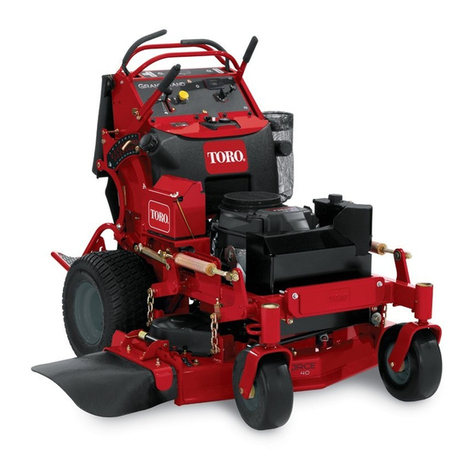
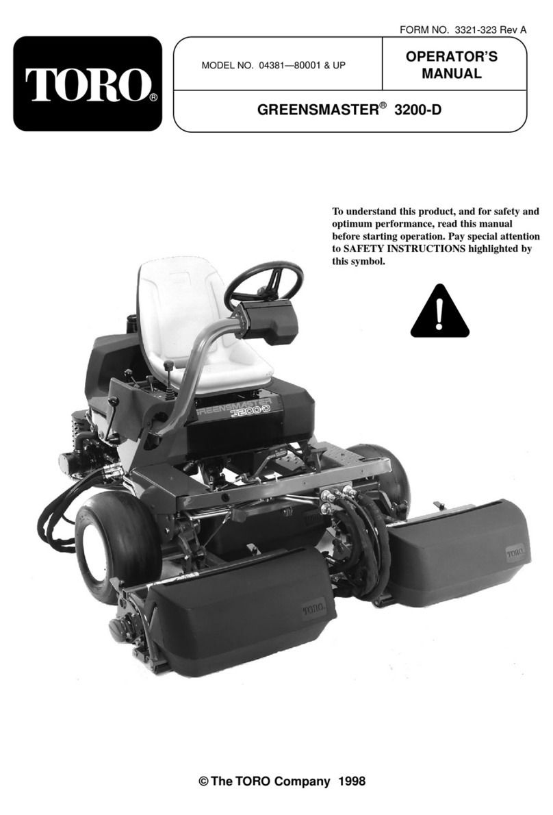
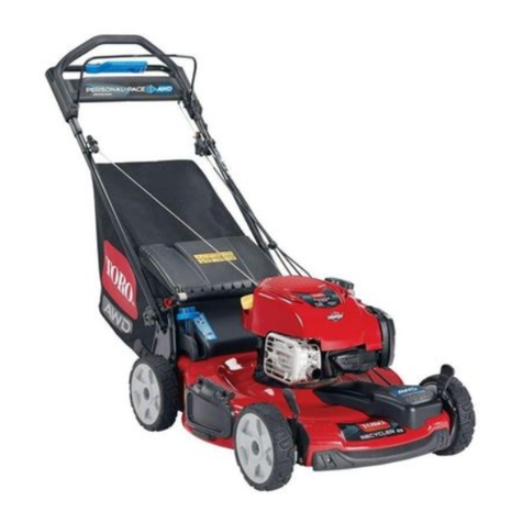
Toro Groundsmaster 360 31223 User manual

FormNo.3424-897RevA
Groundsmaster®3604-Wheel
DriveMulti-PurposeMachine
ModelNo.31223—SerialNo.403330001andUp
ModelNo.31230—SerialNo.403330001andUp
ModelNo.31236—SerialNo.403330001andUp
Registeratwww.Toro.com.
OriginalInstructions(EN)*3424-897*A

ThisproductcomplieswithallrelevantEuropean
directives;fordetails,pleaseseetheseparateproduct
specicDeclarationofConformity(DOC)sheet.
GenuineT orosparkarrestersareapprovedbythe
USDAForestryService.
ItisaviolationofCaliforniaPublicResourceCode
Section4442or4443touseoroperatetheengineon
anyforest-covered,brush-covered,orgrass-covered
landunlesstheengineisequippedwithaspark
arrester,asdenedinSection4442,maintainedin
effectiveworkingorderortheengineisconstructed,
equipped,andmaintainedforthepreventionofre.
Theenclosedengineowner'smanualissupplied
forinformationregardingtheUSEnvironmental
ProtectionAgency(EPA)andtheCaliforniaEmission
ControlRegulationofemissionsystems,maintenance,
andwarranty.Replacementsmaybeorderedthrough
theenginemanufacturer.
WARNING
CALIFORNIA
Proposition65Warning
Dieselengineexhaustandsomeofits
constituentsareknowntotheStateof
Californiatocausecancer,birthdefects,
andotherreproductiveharm.
Batteryposts,terminals,andrelated
accessoriescontainleadandlead
compounds,chemicalsknownto
theStateofCaliforniatocause
cancerandreproductiveharm.Wash
handsafterhandling.
Useofthisproductmaycauseexposure
tochemicalsknowntotheStateof
Californiatocausecancer,birthdefects,
orotherreproductiveharm.
Introduction
Thismachineisaride-on,multi-purposemachine
intendedtobeusedbyprofessional,hiredoperators
incommercialapplications.Itisprimarilydesignedfor
maintaininggrassonwell-maintainedlawnsinparks,
sportselds,andoncommercialgrounds.Itisnot
designedforcuttingbrush.
Important:Tomaximizethesafety,performance,
andproperoperationofthismachine,carefully
readandfullyunderstandthecontentsofthis
Operator’sManual.Failingtofollowthese
operatinginstructionsortoreceiveproper
trainingmayresultininjury.Formoreinformation
onsafeoperatingpractices,includingsafetytips
andtrainingmaterials,gotowww.Toro.com.
YoumaycontactT orodirectlyatwww.Toro.com
forproductsafetyandoperationtrainingmaterials,
accessoryinformation,helpndingadealer,orto
registeryourproduct.
Wheneveryouneedservice,genuineT oroparts,or
additionalinformation,contactanauthorizedT oro
distributororT oroCustomerServiceandhavethe
modelandserialnumbersofyourproductready.
Figure1identiesthelocationofthemodelandserial
numbersontheproduct.Writethenumbersinthe
spaceprovided.
Important:Withyourmobiledevice,youcan
scantheQRcodeontheserialnumberdecal(if
equipped)toaccesswarranty,parts,andother
productinformation.
g235835
Figure1
1.Modelandserialnumberlocation
ModelNo.
SerialNo.
Thismanualidentiespotentialhazardsandhas
safetymessagesidentiedbythesafety-alertsymbol
(Figure2),whichsignalsahazardthatmaycause
seriousinjuryordeathifyoudonotfollowthe
recommendedprecautions.
g000502
Figure2
Safety-alertsymbol
Thismanualalsouses2wordstohighlightinformation.
Importantcallsattentiontospecialmechanical
informationandNoteemphasizesgeneralinformation
worthyofspecialattention.
©2018—TheToro®Company
8111LyndaleAvenueSouth
Bloomington,MN554202
Contactusatwww.Toro.com.
PrintedintheUSA
AllRightsReserved

Contents
Safety.......................................................................4
GeneralSafety...................................................4
SafetyandInstructionalDecals..........................4
Setup......................................................................12
1InstallingthePTODriveshafttoanOptional
MowerDeckorQAS......................................12
2UsingtheOptionalMower-Deck-Mounting
Hardware......................................................13
3AdjustingtheRollBar.....................................13
4CheckingtheTirePressure............................14
5CheckingtheFluidLevels..............................14
ProductOverview...................................................14
Controls...........................................................14
CabControls.................................................17
Specications..................................................18
Attachments/Accessories.................................19
BeforeOperation.................................................19
BeforeOperationSafety...................................19
AddingFuel......................................................20
CheckingtheEngine-OilLevel..........................21
CheckingtheCoolingSystem...........................21
CheckingtheHydraulicSystem........................21
TheSafety-InterlockSystem.............................21
PositioningtheStandardSeat..........................21
RaisingandLoweringtheSeat.........................22
DuringOperation.................................................23
DuringOperationSafety...................................23
StartingtheEngine...........................................25
ShuttingOfftheEngine.....................................26
DrivingtheMachine..........................................26
StoppingtheMachine.......................................26
SelectingtheSteeringMode.............................26
OperatingtheMowerDeckor
Attachment....................................................27
AdjustingtheHeightofCut...............................27
OperatingTips.................................................28
AfterOperation....................................................29
AfterOperationSafety......................................29
PushingtheMachinebyHand..........................29
HaulingtheMachine.........................................29
LocatingtheTie-DownPoints...........................30
Maintenance...........................................................31
MaintenanceSafety..........................................31
RecommendedMaintenanceSchedule(s)...........31
DailyMaintenanceChecklist.............................33
Pre-MaintenanceProcedures..............................34
PreparingtheMachineforMaintenance............34
UsingtheHood-PropRod.................................34
Lubrication..........................................................35
GreasingtheBearingsandBushings................35
EngineMaintenance...........................................37
EngineSafety...................................................37
ServicingtheAirCleaner..................................37
ServicingtheEngineOil....................................37
CheckingtheEngine-OilLevel..........................37
CrankcaseOilCapacity....................................38
ChangingtheEngineOilandFilter....................38
AdjustingtheThrottle........................................39
FuelSystemMaintenance...................................39
ServicingtheWaterSeparator..........................39
BleedingtheFuelSystem.................................40
BleedingAirfromtheFuelInjectors...................40
CleaningtheFuelT ank.....................................41
CheckingtheFuelLinesand
Connections..................................................41
ElectricalSystemMaintenance...........................41
ElectricalSystemSafety...................................41
ServicingtheBattery.........................................41
CheckingtheFuses..........................................42
StoringtheBattery............................................42
DiagnosticAceDisplay.....................................42
CheckingtheInterlockSwitches.......................42
DriveSystemMaintenance..................................45
CheckingtheTirePressure...............................45
CorrectingtheSteeringMisalignment...............45
CoolingSystemMaintenance..............................46
CoolingSystemSafety.....................................46
CheckingtheCoolingSystem..........................46
CleaningtheRadiator.......................................46
BrakeMaintenance.............................................47
AdjustingtheBrakes.........................................47
AdjustingtheParkingBrake.............................47
BeltMaintenance................................................48
CheckingtheAlternatorBelt.............................48
ControlsSystemMaintenance.............................49
AdjustingtheTractionDriveforNeutral.............49
AdjustingtheMaximumGroundSpeed.............49
HydraulicSystemMaintenance...........................50
HydraulicSystemSafety...................................50
HydraulicFluidSpecication.............................50
CheckingtheHydraulicSystem........................50
ChangingtheHydraulicFluidAnd
Filter..............................................................51
CabMaintenance.................................................52
CleaningtheCab..............................................52
FillingtheWasher-FluidBottle..........................52
CleaningtheCabAirFilters..............................52
CleaningtheAir-ConditioningCoil....................53
Cleaning..............................................................54
WasteDisposal.................................................54
Storage...................................................................55
PreparingtheEngine........................................55
PreparingtheMachine......................................55
3
Safety
Thismachinehasbeendesignedinaccordancewith
ENISO5395:2013andANSIB71.4-2017.
GeneralSafety
Thisproductiscapableofamputatinghandsand
feetandofthrowingobjects.Alwaysfollowallsafety
instructionstoavoidseriouspersonalinjury.
Usingthisproductforpurposesotherthanitsintended
usecouldprovedangeroustoyouandbystanders.
•Readandunderstandthecontentsofthis
Operator’sManualbeforestartingtheengine.
•Useyourfullattentionwhileoperatingthe
machine.Donotengageinanyactivitythat
causesdistractions;otherwise,injuryorproperty
damagemayoccur.
•Donotputyourhandsorfeetnearmoving
componentsofthemachine.
•Donotoperatethemachinewithoutallguards
andothersafetyprotectivedevicesinplaceand
workingonthemachine.
•Keepclearofanydischargeopening.Keep
bystandersandpetsasafedistanceawayfrom
themachine.
•Keepchildrenoutoftheoperatingarea.Never
allowchildrentooperatethemachine.
•Stopthemachine,shutofftheengine,removethe
key,andwaitforallmovingpartstostopbefore
servicing,fueling,oruncloggingthemachine.
Improperlyusingormaintainingthismachinecan
resultininjury.Toreducethepotentialforinjury,
complywiththesesafetyinstructionsandalways
payattentiontothesafety-alertsymbol,which
meansCaution,Warning,orDanger—personalsafety
instruction.Failuretocomplywiththeseinstructions
mayresultinpersonalinjuryordeath.
Youcanndadditionalsafetyinformationwhere
neededthroughoutthisOperator’sManual.
SafetyandInstructionalDecals
Safetydecalsandinstructionsareeasilyvisibletotheoperatorandarelocatednearanyarea
ofpotentialdanger.Replaceanydecalthatisdamagedormissing.
decal106-2353
106-2353
1.Electricalpowerpoint
decal106-9206
106-9206
1.Wheel-torquespecications
2.ReadtheOperator'sManual.
decal112-1461
112-1461
1.Beltrouting
4

decal117-3233
117-3233
1.ReadtheOperator'sManualforinformationonfuses.
2.4-wheelsteersolenoid—7.5A
3.PTOenable,4-wheel-steerlamp,decklift,deckoat—7.5A
4.Glowindicator,fuel-runsolenoid,diagnosticlight,start—7.5
A
5.Headlights,deckactuator,powertakeoff—10A
6.Lights—15A
7.Operator-presenceswitch—10A
8.Powerpoint,lights—15A
9.Engine—10A
decal117-3270
117-3270
1.Warning—donottouchthehotsurface.
2.Cutting/dismembermenthazard,hand;entanglement
hazard,belt—stayawayfrommovingparts,keepallguards
andshieldsinplace.
decal117-3272
117-3272
1.Warning—readtheOperator'sManual;failuretousethe
rolloverprotectionsystem(ROPS)canresultininjuryinthe
eventofarollover;wearaseatbeltwhenarollbarisin
place,donotwearaseatbeltwhentherollbarislowered.
decal117-3276
117-3276
1.Enginecoolantunder
pressure
3.Warning—donottouchthe
hotsurface.
2.Explosionhazard—read
theOperator'sManual.
4.Warning—readthe
Operator'sManual.
5

decal117-3277
117-3277
1.Lowerdecks6.Two-wheelsteering
2.Raisedecks7.Four-wheelsteering
3.Engine—stop8.Fast
4.Engine—run9.Continuousvariable
setting
5.Engine—start10.Slow
decal117-4766
117-4766
1.Cutting/dismembermenthazard,fan—stayawayfrom
movingparts;keepallguardsandshieldsinplace.
decal120-0250
120-0250
1.Slow-movingvehicle
decal120-0273
120-0273
6

decal125-7427
125–7427
1.Raise/Lowerdecks5.Engine—run
2.2-wheelsteering6.Engine—start
3.4-wheelsteering7.Fast
4.Engine—stop8.Slow
decal125-9688
125-9688
ModelwithCabOnly
1.Windshieldwipers—off3.Windshieldwipers—on
2.Windshieldwipers4.Spraywindshieldwasher
uid
decal130-0594
130-0594
ModelwithCabOnly
1.Warning—readtheOperator’sManual;whensittinginthe
cab,alwayswearaseatbelt;wearhearingprotection.
7

decal130-0611
130-0611
ModelwithCabOnly
1.Warning—1)Removethepin;2)Raisethedoors;3)Exit
thecab
decaloemmarkt
Manufacturer'sMark
1.Indicatesthatthebladeisidentiedasapartfromthe
originalmachinemanufacturer.
decal132-3600
132-3600
ModelwithCabOnly
1.ReadtheOperator's
Manualformore
informationonfuses.
5.Workinglight(20A)
2.Headlight(25A)6.Auxiliarypower(15A)
3.CondenserfanandA/C
clutch(30A)
7.Cablight(15A)
4.Fan(25A)8.Windshieldwipers(15A)
decal132-6552
132-6552
2-WheelDrivewithROPSand4-WheelDrivewithROPS
ModelsOnly
1.Heightofcut
decal132-6553
132-6553
ModelwithCabOnly
1.Heightofcut
decal133-8062
133-8062
8

decalbatterysymbols
BatterySymbols
Someorallofthesesymbolsareonyourbattery.
1.Explosionhazard6.Keepbystandersasafe
distanceawayfromthe
battery.
2.Nore,opename,or
smoking
7.Weareyeprotection;
explosivegasescan
causeblindnessandother
injuries.
3.Causticliquid/chemical
burnhazard
8.Batteryacidcancause
blindnessorsevereburns.
4.Weareyeprotection.9.Flusheyesimmediately
withwaterandgetmedical
helpfast.
5.ReadtheOperator's
Manual.
10.Containslead;donot
discard.
decal121-8378
121-8378
ModelwithCabOnly
1.Fan—off5.Externalair
2.Fan—onfull6.Internalair
3.Coldair7.Airconditioner—off
4.Hotair8.Airconditioner—on
9

decal117-3273
117-3273
1.Warning—readtheOperator'sManual.6.Thrownobjecthazard—keepbystandersasafedistance
awayfromthemachine.
2.Warning—donotoperatethismachineunlessyouaretrained.7.Warning—engagetheparkingbrake,shutofftheengine,
andremovethekeyfromthekeyswitchbeforeleavingthe
machine.
3.Warning—weartheseatbeltwhenseatedintheoperator's
position.
8.Tippinghazard—lowerthecuttingunitwhendrivingdown
slopes;slowthemachinebeforeturning,donotturnathigh
speeds.
4.Cutting/dismembermenthazardofhandorfoot—removethe
keyfromthekeyswitchandreadtheinstructionsbefore
servicingorperformingmaintenance.
9.Cuttinghazardofhandorfoot—stayawayfrommovingparts;
keepallguardsinplace.
5.Warning—wearhearingprotection.
decal120-0259
120-0259
10

decal132-3378
132-3378
ModelwithCabOnly
1.Raise/Lowerdecks5.Engine—run
2.2-wheelsteering6.Engine—start
3.4-wheelsteering7.Fast
4.Engine—stop8.Slow
11

Setup
LooseParts
Usethechartbelowtoverifythatallpartshavebeenshipped.
ProcedureDescriptionQty.Use
PTOdriveshaft1
Bolt(5/16x1-3/4inches)4
Locknut(5/16inch)4
1Rollpin(3/16x1-1/2inches)2
InstallthePTOdriveshafttoaoptional
deckorQAS.
Retainerpin2
Greasetting2
2Washerheadscrew(5/16x7/8inch)2
Usethehardwaretoinstalltheoptional
mowerdeck.
3Nopartsrequired–Adjusttherollbar.
4Nopartsrequired–Checkthetirepressure.
5Nopartsrequired–Checkthehydraulicuid,engineoil,
andcoolantlevels.
MediaandAdditionalParts
DescriptionQty.Use
Operator'sManual1Reviewitbeforeoperatingthemachine.
Engineowner'smanual1Useittoreferenceengineinformation.
DeclarationofConformity1
Ignitionkeys2Starttheengine.
1
InstallingthePTO
DriveshafttoanOptional
MowerDeckorQAS
Partsneededforthisprocedure:
1PTOdriveshaft
4Bolt(5/16x1-3/4inches)
4Locknut(5/16inch)
2Rollpin(3/16x1-1/2inches)
Procedure
Note:InstallingthePTOdriveshaftiseasierifyou
positionthemachineonahoist.
1.Parkthemachineonalevelsurface,engagethe
parkingbrake,shutofftheengine,andremove
thekey.
WARNING
IfyoustarttheengineandallowthePTO
torotate,seriouspersonalinjuryand
machinedamagecouldresult.
•Donotstarttheengineandengagethe
PTOswitchwhenthePTOdriveshaft
isdisconnectedfromthecuttingdeck.
•BeforeyoudisconnectthePTO
driveshaftfromthecutting
deck,disconnectthePTO
solenoid-valve-coilconnector
fromthewireharnesstoprevent
unintentionallyengagingthePTO
clutch.
2.Disconnectthewire-harnessconnectorfromthe
PTOsolenoid-valve-coilconnector(Figure3).
12

g018339
Figure3
1.Wire-harnessconnector
3.PositionthePTOdriveshaftunderthefrontofthe
machine.Ensurethattheslip-shaftyokeofthe
driveshaftispositionedtowardthetransmission
driveshaft(Figure4).
g018340
Figure4
1.Transmissiondriveshaft4.Locknut
2.Bolt5.Rollpin
3.PTOdriveshaft
4.Alignthesplineandroll-pinholeofthedriveshaft
yokewiththetransmissiondriveshaft.
5.SlidethePTOdriveshaftendyokeontothe
transmissiondriveshaft.
6.SecuretheendyokeofthePTOdriveshaftas
follows:
A.Installtherollpinintheendyokeandshaft.
B.Installtheboltsthroughthedriveshaftend
yoke.
C.Installandtightenthelocknutstosecurethe
endyoketothePTOdriveshaft.
Note:Retaintheremainingbolts,locknuts,
androllpintosecuretheotherendofthe
driveshafttotheattachmentgearboxshaft.
D.Torquethelocknutsto20to25N∙m(175
to225in-lb).
7.LubricatethegreasettingsonthePTO
driveshaft.
8.Afteryouconnecttheotherendofthedriveshaft
totheattachmentgearboxshaft,connect
thewire-harnessconnectortothePTO
solenoid-valve-coilconnector(Figure3).
2
UsingtheOptional
Mower-Deck-Mounting
Hardware
Partsneededforthisprocedure:
2Retainerpin
2Greasetting
2Washerheadscrew(5/16x7/8inch)
Procedure
Note:Thesecomponentsandprocedurearerequired
onlyifamowerdeckthatrequiresretainerpinsis
mountedtothetractionunit.Refertothemowerdeck
Operator’sManualfortheinstallationinstructions.
Note:Ifyouarenotinstallingamowerdeckonthe
tractionunit,removeortieupthe4deck-liftchains
fromtheliftsuspension.
3
AdjustingtheRollBar
NoPartsRequired
Procedure
1.Removethe2hairpinsandthe2pinsfromthe
rollbar(Figure5).
2.Raisetherollbartotheuprightpositionand
secureitwiththe2pinsand2hairpins(Figure
5).
Note:Ifyoumustlowertherollbar,pushthebar
forwardtorelievepressureonthepins,remove
thepins,lowerthebarslowly,andsecureitwith
thepinssothatitdoesnotdamagethehood.
13

g014166
Figure5
1.Rollbar3.Hairpin
2.Pin
4
CheckingtheTirePressure
NoPartsRequired
Procedure
Thetiresareoverinatedforshipping.Therefore,
releasesomeoftheairtoreducethepressure;refer
toCheckingtheTirePressure(page45).
5
CheckingtheFluidLevels
NoPartsRequired
Procedure
1.Checkthehydraulic-uidlevelbeforestarting
theengine,refertoCheckingtheHydraulic
System(page50).
2.Checktheengine-oillevelbeforestartingthe
engine,refertoCheckingtheEngine-OilLevel
(page37).
3.Checkthecoolingsystembeforestartingthe
engine;refertoCheckingtheCoolingSystem
(page46).
ProductOverview
Controls
Becomefamiliarwithallthecontrolsbeforeyoustart
theengineandoperatethemachine.
TractionPedal
Thetractionpedal(Figure6)controlstheforwardand
reverseoperation.Pressthetopofthepedaltomove
forwardandthebottomtomoverearward.Theground
speeddependsonhowfaryoupressthepedal.For
noload,maximumgroundspeed,fullypressthepedal
whilethethrottleisintheFASTposition.
Tostopthemachine,reducethefootpressureon
thetractionpedalandallowittoreturntothecenter
position.
g197397
Figure6
1.Parkingbrake3.Tilt-steeringpedal
2.Brakepedal4.Tractionpedal
BrakePedal
Usethebrakepedalwiththebrake-pedallatchto
engageanddisengagetheparkingbrake(Figure
6).Tostopthemachine,releasethetractionpedal
andallowittoreturntothecenterposition.Youcan
usethebraketoassistinstoppingthemachineinan
emergencysituation.
Tilt-SteeringPedal
Totiltthesteeringwheeltowardyou,pressthefoot
pedaldown,pullthesteeringtowertowardyouto
themostcomfortableposition,andreleasethepedal
(Figure6).Tomovethesteeringwheelawayfrom
14

you,pressthefootpedalandreleaseitwhenthe
steeringwheelreachesthedesiredoperatingposition.
ParkingBrake
Toengagetheparkingbrake,pushdownonthebrake
pedalandpressthetopforwardtolatchit(Figure
6).T odisengagetheparkingbrake,pressthebrake
pedaluntiltheparking-brakelatchretracts.
KeySwitch
Theignitionswitchhas3positions:OFF,ON/PREHEAT,
andSTART(Figure7).
g014169
Figure7
1.Power-takeoff(PTO)
switch
8.Diagnosticlight
(4-wheel-driveonly)
2.Oil-pressure-warninglight9.Ignitionswitch
3.Charge-indicatorlight10.Powerpoint
4.Hourmeter11.Optionalswitchlocation
5.Differential-lockswitch
(2-wheel-driveonly)
12.Deck-liftswitch
6.Steering-selectorswitch
(4-wheel-driveonly)
13.Glow-pluglight
7.Throttlelever14.Coolant-temperature-warning
light
Power-Takeoff(PTO)Switch
Thepower-takeoff(PTO)switchstartsandstopsthe
attachment(Figure7).
FuelGauge
Thefuelgauge(Figure8)indicatestheamountoffuel
remaininginthefueltank.
g014170
Figure8
1.Fuelgauge2.Fuel-tankcap
ThrottleLever
Thethrottlelever(Figure7)controlstheengine
speed.Movingthethrottleleverforwardtowardthe
FASTpositionincreasestheenginespeed.Moving
itrearwardtowardtheSLOWpositiondecreasesthe
enginespeed.Thethrottlecontrolsthespeedofthe
PTOand,withthetractionpedal,controlstheground
speedofthemachine.Alwaysrunthemachine
withthethrottleintheFASTpositionwhenoperating
attachments.
HourMeter
Thehourmeter(Figure7)recordsthenumberof
hoursthattheenginehasoperated.Itoperateswhen
thekeyswitchisintheRUNposition.Usethesetimes
forschedulingregularmaintenance.
Engine-Coolant-Temperature-Warning
Light
Thislightglowsandtheattachmentstopsifthe
temperatureoftheenginecoolantishigh(Figure
7).Ifyoudonotstopthemachineandthecoolant
temperaturerisesanother7°C(20°F),theengine
shutsoff.
Important:Iftheattachmentshutsdownand
thetemperaturewarninglightison,pushthe
PTOknobdown,drivethemachinetoasafe,at
area,movethethrottlelevertotheSLOWposition,
allowthetractionpedaltomovetotheNEUTRAL
position,andengagetheparkingbrake.Allowthe
enginetoidleforseveralminuteswhileitcoolsto
asafelevel.Shutofftheengineandcheckthe
coolingsystem;refertoCheckingtheCooling
System(page46).
15

Glow-Plug-IndicatorLight(Orange
Light)
Theglow-plug-indicatorlight(Figure7)turnsonwhen
youturntheignitionswitchtotheONposition.It
remainsonfor6seconds.Whenthelightturnsoff,
youcanstarttheengine.
Charge-IndicatorLight
Thecharge-indicatorlightilluminateswhenthe
charging-systemcircuitmalfunctions(Figure7).
Oil-PressureWarningLight
Theoil-pressurewarninglightglowsiftheengine-oil
pressuredropsbelowasafelevel(Figure7).Ifthe
oilpressureislow,shutofftheengineanddetermine
thecause.Repairtheengine-oilsystembeforeyou
starttheengineagain.
SteeringSelectorSwitch
4-WheelDriveMachinesOnly
Pressthesteeringselectorswitchtotherearto
engage4-wheelsteeringandforwardtoreturnto
2-wheelsteering(Figure7).
DiagnosticLight
4-WheelDriveMachinesOnly
Thediagnosticlightilluminateswhenthesystem
detectsafault(Figure7).
UnderstandingtheDiagnostic
Light
4-WheelDriveMachinesOnly
Themachinecomeswithadiagnosticlightthat
indicatesiftheelectroniccontrollersensesan
electronicmalfunction.Thediagnosticlightislocated
onthecontrolpanel(Figure9).Whentheelectronic
controllerisfunctioningcorrectlyandthekeyswitch
ismovedtotheONposition,thecontrollerdiagnostic
lightturnsonfor3secondsandturnofftoindicatethat
thelightisworkingproperly.Iftheengineshutsoff,the
lightturnsonsteadyuntilyouchangethekeyposition.
Thelightblinksifthecontrollerdetectsamalfunction
intheelectricalsystem.Thelightstopsblinkingand
automaticallyresetswhenyouturnthekeyswitchto
theOFFpositionwhenthefaulthasbeenresolved.
g014333
Figure9
1.Diagnosticlight
Whenthecontrollerdiagnosticlightblinks,1of
thefollowingproblemshasbeendetectedbythe
controller:
•Anoutputhasbeenshorted.
•Anoutputhasanopencircuit.
Usethediagnosticacedisplaytodeterminewhich
outputismalfunctioning.
Ifthediagnosticlightdoesnotcomeonwhenthekey
switchisintheONposition,thisindicatesthatthe
electroniccontrollerisnotoperating.Possiblecauses
areasfollows:
•Thelightisburnedout.
•Thefusesareblown.
•Theelectroniccontrollerisnotfunctioning
correctly.
Checktheelectricalconnections,inputfuses,and
diagnosticlightbulbtodeterminethemalfunction.
Ensurethattheloop-backconnectorissecuredtothe
wire-harnessconnector.
16

DiagnosticAceDisplay
Themachinecomeswithanelectroniccontroller
whichcontrolsmostofthemachinefunctions.The
controllerdetermineswhatfunctionisrequiredfor
variousinputswitches(e.g.,seatswitchandkey
switch)andturnsontheoutputstoactuatesolenoids
orrelaysfortherequestedmachinefunction.
Fortheelectroniccontrollertocontrolthemachineas
desired,eachoftheinputswitches,outputsolenoids,
andrelaysmustbeconnectedandfunctioning
properly.
UsetheDiagnosticACEdisplaytoolandtheoverlay
tohelpverifyandcorrectelectricalfunctionsofthe
machine.ContactyourauthorizedTorodistributorfor
assistance.
CabControls
ModelwithCabOnly
g198816
Figure10
1.Fancontrol4.Air-conditioningswitch
2.Temperaturecontrol5.Air-recirculationcontrol
3.Windshield-wiperswitch
Air-RecirculationControl
Setsthecabtoeitherrecirculatetheairinthecabinor
todrawairintothecabinfromoutside(Figure10).
•Setittorecirculatetheairwhenusingthe
air-conditioning.
•Setittodrawairinwhenusingtheheaterorfan.
Fan-ControlKnob
Rotatethefan-controlknobtoregulatethespeedof
thefan(Figure10).
Temperature-Control-Knob
Rotatethetemperature-controlknobtoregulatethe
airtemperatureinthecab(Figure10).
Windshield-WiperSwitch
Usethisswitchtoturnthewindshieldwipersonor
off(Figure10).
Air-ConditioningSwitch
Usethisswitchtoturntheairconditioningonoroff
(Figure10).
WindshieldLatch
Liftupthelatchtoopenthewindshield(Figure11).
Pressinthelatchtolockthewindshieldintheopen
position.Pulloutanddownonthelatchtocloseand
securethewindshield.
g196911
Figure11
1.Windshieldlatch
RearWindowLatch
Liftupthelatchestoopentherearwindow.Pressin
onthelatchtolockthewindowinOPENposition.Pull
outanddownonthelatchtocloseandsecurethe
window(Figure11).
Important:Closetherearwindowbeforeopening
thehoodordamagemayoccurtothehoodorrear
window.
17

Specications
Note:Specicationsanddesignaresubjecttochangewithoutnotice.
g197702
Figure12
DescriptionFigure12
reference
DimensionorWeight
HeightwithrollbarupC201cm(79inches)
HeightwithrollbardownG137cm(54inches)
HeightwithcabD225cm(88-1/2inches)
OveralllengthF276cm(108-1/2inches)
OverallwidthB147cm(58inches)
WheelbaseE155cm(61inches)
Wheeltread(tirecentertocenter)rearA112cm(44inches)
Groundclearance15cm(6inches)
18

WeightoftheMachinewithMowerDecks
4-Wheel
Drive
Machine
withROPS
Machine
withCab
2-Wheel
Drive
Machine
withROPS
Nomower
deck
1,134kg
(2,500lb)
1,361kg
(3,000lb)
1,088kg
(2,398lb)
72inchside
discharge
mowerdeck
1,344kg
(2,964lb)
1,571kg
(3,464lb)
1,298kg
(2,862lb)
72inchbase
mowerdeck
1,323kg
(2,916lb)
1,549kg
(3,416lb)
1,276kg
(2,814lb)
62inchbase
mowerdeck
1,305kg
(2,878lb)
1,532kg
(3,378lb)
1,259kg
(2,776lb)
100inchrear
discharge
mowerdeck
1,492kg
(3,290lb)
1,719kg
(3,790lb)
1,446kg
(3,188lb)
Attachments/Accessories
AselectionofT oroapprovedattachmentsand
accessoriesisavailableforusewiththemachine
toenhanceandexpanditscapabilities.Contact
yourAuthorizedServiceDealerorauthorizedToro
distributororgotowww.T oro.comforalistofall
approvedattachmentsandaccessories.
Toensureoptimumperformanceandcontinuedsafety
certicationofthemachine,useonlygenuineT oro
replacementpartsandaccessories.Replacement
partsandaccessoriesmadebyothermanufacturers
couldbedangerous,andsuchusecouldvoidthe
productwarranty.
Operation
Note:Determinetheleftandrightsidesofthe
machinefromthenormaloperatingposition.
BeforeOperation
BeforeOperationSafety
GeneralSafety
•Neverallowchildrenoruntrainedpeopleto
operateorservicethemachine.Localregulations
mayrestricttheageoftheoperator.Theowner
isresponsiblefortrainingalloperatorsand
mechanics.
•Becomefamiliarwiththesafeoperationofthe
equipment,operatorcontrols,andsafetysigns.
•Knowhowtostopthemachineandshutoffthe
enginequickly.
•Checkthatoperator-presencecontrols,safety
switches,andshieldsareattachedandfunctioning
properly.Donotoperatethemachineunlessthey
arefunctioningproperly.
•Beforemowing,alwaysinspectthemachineto
ensurethattheblades,bladebolts,andcutting
assembliesareingoodworkingcondition.
Replacewornordamagedbladesandboltsinsets
topreservebalance.
•Inspecttheareawhereyouwillusethemachine
andremoveallobjectsthatthemachinecould
throw.
FuelSafety
•Useextremecareinhandlingfuel.Itisammable
anditsvaporsareexplosive.
•Extinguishallcigarettes,cigars,pipes,andother
sourcesofignition.
•Useonlyanapprovedfuelcontainer.
•Donotremovethefuelcaporllthefueltank
whiletheengineisrunningorhot.
•Donotaddordrainfuelinanenclosedspace.
•Donotstorethemachineorfuelcontainerwhere
thereisanopename,spark,orpilotlight,such
asonawaterheaterorotherappliance.
•Ifyouspillfuel,donotattempttostarttheengine;
avoidcreatinganysourceofignitionuntilthefuel
vaporshavedissipated.
19

AddingFuel
FuelSpecication
•Neverusekeroseneorgasolineinsteadofdiesel
fuel.
•Nevermixkeroseneorusedengineoilwiththe
dieselfuel.
•Neverkeepfuelincontainerswithzincplatingon
theinside.
•Donotusefueladditives.
PetroleumDiesel
Cetanerating:40orhigher
Sulfurcontent:Lowsulfur(<500ppm)orultra-low
sulfur(<15ppm)
FuelTable
DieselfuelspecicationLocation
ASTMD975
No.1-DS15
No.2-DS15
USA
EN590EuropeanUnion
ISO8217DMXInternational
JISK2204GradeNo.2Japan
KSM-2610Korea
•Useonlyclean,freshdieselfuelorbiodieselfuels.
•Purchasefuelinquantitiesthatcanbeusedwithin
180daystoensurefuelfreshness.
Usesummer-gradedieselfuel(No.2-D)at
temperaturesabove-7°C(20°F)andwinter-grade
fuel(No.1-DorNo.1-D/2-Dblend)belowthat
temperature.
Note:Useofwinter-gradefuelatlowertemperatures
provideslowerashpointandcoldowcharacteristics
whicheasesstartingandreducesfuellterplugging.
Usingsummer-gradefuelabove-7°C(20°F)
contributestowardlongerfuelpumplifeandincreased
powercomparedtowinter-gradefuel.
UsingBiodiesel
Thismachinecanalsouseabiodiesel-blendedfuelof
uptoB20(20%biodiesel,80%petrodiesel).
Sulfurcontent:Ultra-lowsulfur(<15ppm)
Biodieselfuelspecication:ASTMD6751or
EN14214
Blendedfuelspecication:ASTMD975,EN590,
orJISK2204
Important:Thepetroleumdieselportionmust
beultra-lowsulfur.
Observethefollowingprecautions:
•Biodieselblendsmaydamagepaintedsurfaces.
•UseB5(biodieselcontentof5%)orlesserblends
incoldweather.
•Monitorseals,hoses,gasketsincontactwithfuel
astheymaydegradeovertime.
•Fuellterpluggingmayoccurforatimeafteryou
converttobiodieselblends.
•Formoreinformationonbiodiesel,contactyour
authorizedT orodistributor.
FuelTankCapacity
51L(13.5USgallons)
FillingtheFuelTank
Note:Ifpossible,llthefueltankaftereachuse.This
minimizespossiblebuildupofcondensationinsidethe
fueltank.
Addfueltothefueltankuntilthelevelisevenwiththe
bottomofthellerneck.Donotoverllthefueltank.
g236327
Figure13
20
This manual suits for next models
4
Table of contents
Other Toro Lawn Mower manuals

Toro
Toro 04054 Greensmaster 800 User manual

Toro
Toro Groundsmaster 3280-D User manual

Toro
Toro Reelmaster 3555 Series User manual

Toro
Toro 30607A User manual

Toro
Toro Reelmaster 3550-D User manual

Toro
Toro 72200 User manual

Toro
Toro 22196 User manual

Toro
Toro Recycler 20370 User manual

Toro
Toro Recycler 20379 User manual

Toro
Toro 30672 User manual

Toro
Toro eS3200DC 72V User manual

Toro
Toro 74164 User manual

Toro
Toro 30316 User manual

Toro
Toro 20833 User manual

Toro
Toro 30434 User manual

Toro
Toro Groundsmaster e3200 User manual

Toro
Toro ProLine 30180 User manual

Toro
Toro Groundsmaster 3280-D User manual

Toro
Toro 22298 User manual

Toro
Toro Recycler 20651 User manual