Toro Reelmaster 3555 Series User manual
Other Toro Lawn Mower manuals
Toro
Toro 21472 User manual
Toro
Toro 21467T User manual

Toro
Toro Groundsmaster 4110 User manual
Toro
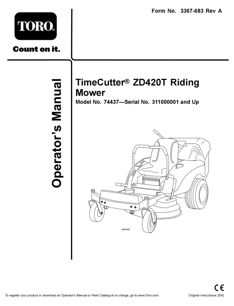
Toro 74437 User manual

Toro
Toro 3431 User manual
Toro
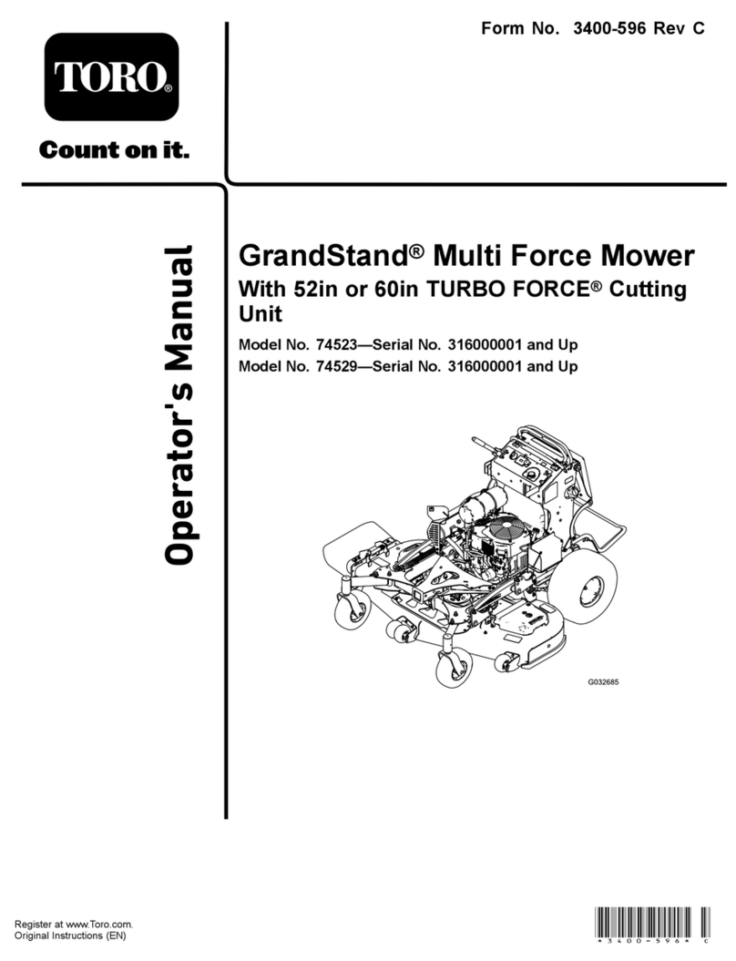
Toro 74523 User manual
Toro
Toro 22157 User manual
Toro
Toro Recycler 20652 User manual

Toro
Toro Reelmaster 5010- H User manual
Toro
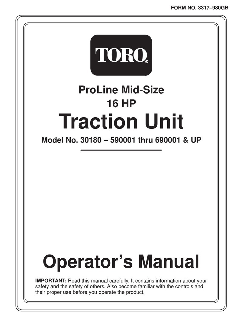
Toro ProLine 30180 User manual
Toro
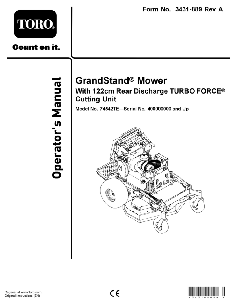
Toro 74542TE User manual

Toro
Toro GrandStand 74534 User manual

Toro
Toro Super Recycler 20382 User manual

Toro
Toro 3550 User manual
Toro
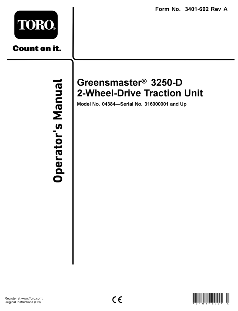
Toro 4384 User manual

Toro
Toro 30144 User manual
Toro
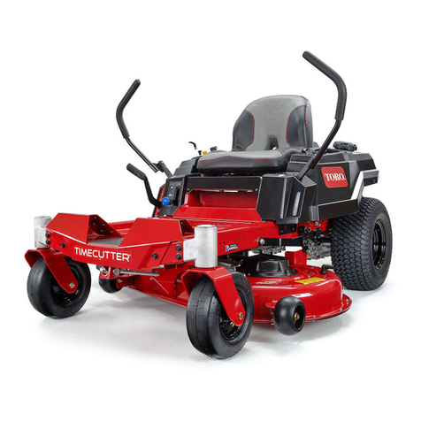
Toro timecutter zs 4200t User manual
Toro
Toro 74410 User manual

Toro
Toro HoverPro 550 User manual
Toro
Toro Recycler 21767 User manual
Popular Lawn Mower manuals by other brands

DEWEZE
DEWEZE ATM-725 Operation and service manual

Weed Eater
Weed Eater 180083 owner's manual

Husqvarna
Husqvarna Poulan Pro PP185A42 Operator's manual

Better Outdoor Products
Better Outdoor Products Quick Series Operator's manual

Cub Cadet
Cub Cadet 23HP Z-Force 60 Operator's and service manual

MTD
MTD 795, 792, 791, 790 Operator's manual
