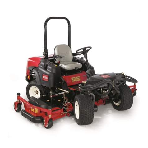
Toro Groundsmaster 223D User manual

(8
+( #(8
//,*+65(5(48('
!
6+47
!
!
!
+( ! &21)2405 62 6+(
0(4,&$1 $6,21$/ 6$1'$4'5 156,676(5 5$)(6;
56$1'$4'5 )24 4,',1* 029(45 9+(1 9(,*+65 $4(
,156$//(' $&&24',1* 62 &+$46 21 3$*( 6+75
3427'/; ',53/$;5 6+( 5$)(6; 5($/
2 $5574( 0$:,070 5$)(6; 236,070 3(4)240$1&(
$1' 62 *$,1 .129/('*( 2) 6+( 342'7&6 ,6 ,5 (55(16,$/
6+$6 ;27 24 $1; 26+(4 23(4$624 2) 6+( 029(4 4($'
$1' 71'(456$1' 6+( &216(165 2) 6+,5 0$17$/ %()24(
6+( (1*,1( ,5 (8(4 56$46(' $; 3$46,&7/$4 $66(16,21 62
6+( # ! +,*+/,*+6(' %; 6+,5
5;0%2/ <
+( 5$)(6; $/(46 5;0%2/ 0($15 !
" 24 3(4521$/ 5$)(6;
,15647&6,21 $,/74( 62 &203/; 9,6+ 6+( ,15647&6,21
0$; 4(57/6 ,1 3(4521$/ ,1-74;

The GROUND MA TER 223-D was developed to satisfy the demand for a maneuverable, intermediate size, turf
maintenance rotary mower. The machine has advanced concepts in engineering, design and safety; and if
maintained properly, it will give excellent service.
ince the GROUND MA TER 223-D is a high quality product, Toro is concerned about the future use of the
machine and the safety of the user. Read this manual to familiarize yourself with the proper set up, operation, and
maintenance instructions. The major sections of this manual are:
"$ !" #"!
" !" #"!
"
" !" #"!
"
Certain information in this manual is emphasized. DANGER, WARNING and CAUTION identify personal safety
related information. IMPORTANT identifies mechanical information demanding special attention. Be sure to read the
directive because it deals with the possibility of damaging a part or parts of the machine. NOTE identifies general
information worthy of special attention.
If help concerning set up, operation, maintenance or safety is ever needed, contact a local Authorized Toro
Distributor. In addition to genuine Toro replacement parts, the distributor also has optional equipment form the
complete line of Toro turf care equipment. Keep your Toro all Toro Ċ buy genuine Toro replacement parts and
accessories.
The engine exhaust from this product
contains chemicals known to the State of
California to cause cancer, birth defects,
or other reproductive harm.
Because in some areas there are local, state or federal regulations requiring that a spark arrestor muffler be used on
the engine of this mower, a spark arrestor screen is available as an option. If a spark arrestor muffler is required,
order the following part from you Authorized Toro Distributor.
(1)75-6880 park Arrestor creen
This part is certified to meet the requirements of U DA Forest ervice tandard No. 5100-1A.
When the mower is used or operated on any California forest, brush or grass covered land, a properly operating
spark arrester must be attached to the muffler. The operator is violating state law, ection 442 Public Resources
Code if a spark arrester is not used.
Whenever you have questions or need service, contact your local authorized Toro Distributor. In addition to having a
complete line of accessories and professional turf care service technicians, the distributor has a complete line of
genuine TORO replacement parts to keep your machine operating properly. Keep your TORO all TORO. Buy
genuine TORO parts and accessories.

! !!
!% !"!
!% !"!
!
! !
!" !"!
!
Check Engine Oil 12. . . . . . . . . . . . . . . . . . . . . . . . .
Check Cooling System 12. . . . . . . . . . . . . . . . . . . .
Check Hydraulic System Fluid 13. . . . . . . . . . . . .
Fill Fuel ank 14. . . . . . . . . . . . . . . . . . . . . . . . . . . . .
!
! !"!
Starting and Stopping 16. . . . . . . . . . . . . . . . . . . . .
Bleeding Fuel System 17. . . . . . . . . . . . . . . . . . . . .
Checking Interlock System 18. . . . . . . . . . . . . . . .
Operating Characteristics 18. . . . . . . . . . . . . . . . . .
Pushing Or owing raction Unit 19. . . . . . . . . . . .
"!
Greasing Bearings And Bushings 19. . . . . . . . . . .
% ! !
# !# !
!
General Air Cleaner Maintenance 22. . . . . . . . . . .
Servicing Dust Cup and Baffle 22. . . . . . . . . . . . . .
Servicing Air Cleaner Filter 22. . . . . . . . . . . . . . . . .
Inspecting Filter Element 23. . . . . . . . . . . . . . . . . .
Cleaning Radiator And Screen 23. . . . . . . . . . . . .
Changing Engine Oil And Filter 23. . . . . . . . . . . . .
Servicing Fuel System 24. . . . . . . . . . . . . . . . . . . . .
Bleeding Air From Injectors 25. . . . . . . . . . . . . . . .
Servicing Engine Belts 25. . . . . . . . . . . . . . . . . . . .
P O Belt 26. . . . . . . . . . . . . . . . . . . . . . . . . . . . . . . .
P O Clutch Adjustment 27. . . . . . . . . . . . . . . . . . .
Changing Coolant In Cooling System 27. . . . . . .
Adjusting ransmission For Neutral 27. . . . . . . . .
Changing Hydraulic Oil And Filter 27. . . . . . . . . . .
Adjusting Service Brakes 28. . . . . . . . . . . . . . . . . .
Servicing Battery 29. . . . . . . . . . . . . . . . . . . . . . . . .
Wiring Harness Service 29. . . . . . . . . . . . . . . . . . . .
Fuses 29. . . . . . . . . . . . . . . . . . . . . . . . . . . . . . . . . . .
%" !
! !
! !
! "
"! !!
!
! ! &(0 4:*6
!% !"!
!-* " ! ;&7 8*78*) &3)
(*68.+.*) '< ! +46 (4251.&3(* ;.8- 8-*
> 75*(.+.(&8.437 4+ 8-* 2*6.(&3 &8.43&1
8&3)&6)7 378.898* 18-49,- -&=&6) (438641 &3)
&((.)*38 56*:*38.43 5&68.&11< &6* )*5*3)*38 9543
8-* )*7.,3 &3) (43+.,96&8.43 4+ 8-* 2&(-.3* 8-*7*
+&(8467 &6* &174 )*5*3)*38 9543 8-* &;&6*3*77
(43(*63 &3) 5645*6 86&.3.3, 4+ 8-* 5*67433*1
.3:41:*) .3 8-* 45*6&8.43 86&375468 2&.38*3&3(*
&3) 7846&,* 4+ 8-* 2&(-.3* 25645*6 97* 46
2&.38*3&3(* 4+ 8-* 2&(-.3* (&3 6*7918 .3 .3/96< 46
)*&8- !4 6*)9(* 8-* 548*38.&1 +46 .3/96< 46 )*&8-
(4251< ;.8- 8-* +4114;.3, 7&+*8< .37869(8.437
$ Engine exhaust contains carbon
monoxide which is an odorless, deadly poison. Carbon
monoxide is also known to the State of California to
cause birth defects. Do not run engine indoors or in an
enclosed area.
!
Read and understand the contents of this manual
before starting and operating the machine. Become
familiar with the controls and know how to stop the
machine and engine quickly. A free replacement
manual is available by sending the complete model
and serial number to:
he oro Company
8111 Lyndale Avenue South
Minneapolis, Minnesota 55420-1196.
Never allow children to operate the machine. Do
not allow adults to operate machine without proper
instruction. Only trained operators who have read this
manual should operate this machine.

Never operate the machine when under the
influence of drugs or alcohol.
Remove all de ris or other o jects that might e
picked up and thrown y the lades or fast moving
components from other attached implements. Keep all
ystanders away from operating area.
Keep all shields, safety devices and decals in
place. If a shield, safety device or decal is defective,
illegi le or damaged, repair or replace it efore
operating the machine. Also tighten any loose nuts,
olts or screws to ensure machine is in safe operating
condition.
Always wear su stantial shoes. Do not operate
machine while wearing sandals, tennis shoes,
sneakers or when arefoot. Do not wear loose fitting
clothing that could get caught in moving parts and
possi ly cause personal injury. Wearing safety
glasses, safety shoes, long pants and a helmet is
advisa le and required y some local ordinances and
insurance regulations.
Check interlock switches daily for proper operation
(Refer To Checking Interlock Switches, Page 18). Do
not rely entirely on safety switches Ćshut off engine
efore getting off seat. If a switch fails, replace it efore
operating the machine. The interlock system is for your
protection, so do not ypass it. Replace all interlock
switches every two years. Interlock switches should e
adjusted so:
A. Engine cannot e started unless traction pedal
is released (neutral position)Ċand PTO lever is
DISENGAGED (off position).
B. Engine stops if operator gets off seat when
traction pedal is depressed.
C. Engine stops if operator gets off seat when
PTO lever is ENGAGED (on position).
Grass deflectors must e installed in lowest
position on side discharge units.
Since diesel fuel is highly flamma le, handle it
carefully:
A. Use an approved fuel container.
B. Do not remove fuel tank cap while engine is hot
or running.
C. Do not smoke while handling fuel.
D. Fill fuel tank outdoors and only to within an inch
from the top of the tank, not the filler neck. Do not
overfill.
E. Wipe up any spilled fuel.
Sit on the seat when starting and operating the
machine.
Before starting the engine:
A. Engage the parking rake.
B. Make sure traction pedal is in NEUTRAL and
PTO switch in OFF position.
C. After engine is started, release parking rake
and keep foot off traction pedal. Machine must not
move. If movement is evident, the neutral return
mechanism is adjusted incorrectly; therefore, shut
engine off and adjust until machine does not move
when traction pedal is released.
Seating capacity is one person. Therefore, never
carry passengers.
Do not run engine in a confined area without
adequate ventilation. Exhaust fumes are hazardous
and could possi ly e deadly.
Make sure seat elt can e removed quickly if
machine is driven or rolls into a pond or lake.
Traverse slopes carefully. Do not start or stop
suddenly when traveling uphill or downhill.
When operating a 4 wheel drive machine or any
machine on slopes, y anks or drop offs, always have
ROPS (roll over protection system) installed.
When operating a machine with ROPS (roll over
protection system) always use seat elt and make sure
seat pivot retaining pin is installed.
Operator must e skilled and trained in how to
drive on hillsides. Failure to use caution on slopes or
hills may cause loss of control and vehicle to tip or roll
possi ly resulting in personal injury or death.
This product may exceed noise levels of 85 dB(A)
at the operator position. Ear protectors are
recommended for prolonged exposure to reduce the
potential of permanent hearing damage.
Using the machine demands attention and to
prevent loss of control:
A. Operate only in daylight or when there is good
artificial light.
B. Drive slowly. Avoid sudden stops and starts.
C. Watch for holes or other hidden hazards.
D. Look ehind machine efore acking up.
E. Do not drive close to a sand trap, ditch, creek
or other hazard.
F. Reduce speed when making sharp turns and
turning on a hillside.
G. The cutting deck must e lowered when going
down slopes for steering control.

!
Check carefully for overhead clearances such as
branches, doorways, electrical wires, before driving
under any ob ects and do not contact them.
If engine stalls or loses headway and cannot make
it to the top of a slope, do not turn machine around.
Always back slowly straight down the slope.
Never raise the cutting unit or other attached
implement while the blades or other parts are rotating.
The grass deflector must always be installed and in
the lowest position on the cutting unit. This product is
designed to drive ob ects into the ground where they
lose energy quickly in grassy areas.
! When a person or pet appears
unexpectedly in or near the mowing area,
. Careless operation, combined with terrain
angles, ricochets, or improperly positioned guards can
lead to thrown ob ect in uries. Do not resume mowing
until area is cleared.
Do not touch engine, muffler or exhaust pipe while
engine is running or soon after it is stopped. These
areas could be hot enough to cause burns.
If cutting deck strikes a solid ob ect or vibrates
abnormally, stop immediately, turn engine off, set
parking brake and wait for all motion to stop. Inspect for
damage. If damaged, repair or replace any
components before operating.
Before getting off the seat:
A. Move traction pedal to neutral position and
remove foot from pedal.
B. Set the parking brake and turn the PTO switch
OFF.
C. Shut the engine OFF and remove key from
ignition switch. Wait for all machine movement to
stop before getting off the seat.
Before servicing or making ad ustments, stop
engine and remove key from the switch.
Make sure machine is in safe operating condition
by keeping all nuts, bolts and screws tight.
Make sure all hydraulic line connectors are tight,
and all hydraulic hoses and lines are in good condition
before applying pressure to the system.
Keep body and hands away from pin hole leaks or
nozzles that e ect high pressure hydraulic fluid. Use
cardboard or paper to find hydraulic leaks. Hydraulic
fluid escaping under pressure can penetrate skin and
cause in ury. Fluid accidentally in ected into the skin
must be surgically removed within a few hours by a
doctor familiar with this form of in ury or gangrene may
result.
Before disconnecting or performing any work on
the hydraulic system, all pressure in system must be
relieved by stopping engine and lowering implement
to the ground.
If ma or repairs are ever needed or assistance is
desired, contact an Authorized Toro Distributor.
To reduce potential fire hazard, keep engine area
free of excessive grease, grass, leaves and dirt.
If engine must be running to perform maintenance
or an ad ustment, keep hands, feet, clothing and other
parts of the body away from cutting deck and other
moving parts. Keep all bystanders away.
Do not overspeed the engine by changing
governor setting. To assure safety and accuracy, have
an Authorized Toro Distributor check maximum engine
speed.
Periodically inspect the roll bar and roll bar
mounting. Replace, if necessary. Do not modify roll
over protection frames or structures because they are
specifically designed, sized, located, and tested for
in ury reduction. If a rollover occurs, a modified ROPS
will not provide adequate protection.
Shut engine off before checking or adding oil to the
crankcase.
At the time of manufacture, the machine
conformed to the safety standards for riding mowers
when weights are installed according to chart on page
11. To assure optimum performance and continued
safety certification of the machine, use genuine Toro
replacement parts and accessories. Replacement
parts and accessories made by other manufacturers
may result in nonĆconformance with the safety
standards, and the warranty may be voided.

!& !"!
The following safety and instruction decals are affixed to the traction unit. If any decal becomes illegible or damaged,
install a new decal. Part numbers are listed below and in your Parts Catalog.
"
')* (
! # $
')* (
! ! !
')* (
! ! $!
')* (
! "
')* (
! !
')* (
! !
')* (
')* (
"
')* (
! %
')* (
! % #
')* (
! %
')* (
!!
"!
! "
!!
"

!
0*,0(
Manufacturer Ċ Mitsubishi.
Horsepower Ċ 22 (16 w) @ 3000 RPM.
Torque Ċ 40 ft-lb (54.2 Nm) @ 2400 RPM.
Displacement Ċ 58.1 cu in. (952 cc).
Crankcase Capacity Ċ 3.8 qt. (3.6 L).
Governor Ċ Mechanical.
Governor Limit Ċ 3100Ć3250 RPM.
Idle Speed Ċ 1700 RPM.
,3 .(%0(3 Donaldson heavy duty with precleaner.
Remote mounted.
6(. !%0- %2%&,5: 8.5 gal. (32 l).
6(. ,.5(3$%5(3 (2%3%513 3 micron spinĆon type
element. Replaceable (Toro Part No. 63-8300).
6(. 6/2 12 volt electric (transistor type)
w/replaceable fuel filter (Toro Part No. 43-2550).
11.,0* :45(/
Radiator Ċ Approx. 6 qt (5.7 l) capacity.
Expansion Tank Ċ Remote mounted; 1 qt (0.946 l)
capacity. System contains a 50/50 mix of ethylene
glycol antiĆfreeze and water.
.(&53,&%. Battery Ċ 12 volt, BCI group size 26,530
Amp at 0 F. 35 amp alternator with regulator/rectifier.
3,7( 162.,0* Transmission driven by steel shaft
with flexible rubber couplings at each end.
!3%04/,44,10
Manufacturer & Type Ċ Sundstrand hydrostatic,
Type U15.
Normal Charge Pressure Ċ 70Ć150 psi
(483Ć1034 kPa).
Implement Relief Setting Ċ 700Ć800 psi
(4 826 Ć 5 516 kPa).
:'3%6.,& ,.5(3 25 micron mounted directly to
transmission. Replaceable (Toro Part No. 23-2300).
3,7( 9.( Manufacturer Ċ Dana Corp., Model GTĆ20.
Axle serves as a hydraulic fluid reservoir and mates
directly with the transmission. Approximately 5 qt (4.7 l)
capacity.
3%-(4 Mechanical drum type, 7 in. (17.8 cm) dia. x
1Ć3/4 in. (45 mm) wide. Individually controlled by two
pedals connected by cable and conduit for steering
assist. Pedals may be latched together for two wheel
braking. Lever provided for parking brake.
!,3(4 $+((.4 3(4463(
Front Tires Ċ 23 x 8.50 - 12
Rear Tires Ċ 16 x 6.50 - 8
All tires 4 ply rating, tubeless type.
(Pressure Ċ 20 psi (138 kPa).
5((3,0* 13 in. (33 cm) steering wheel. TRW power
steering valve.
%,0 3%/( Frame is welded, formed steel.
04536/(05%5,10 Fuel gauge, water temperature
gauge, hour meter and warning lights for high
temperature shutdown, oil pressure, amperage and
glow plug are mounted on the console.
10531.4 Throttle, PTO switch, parking brake,
implement lift, ignition switch and glow plug switch are
all handĆoperated. Forward/reverse traction pedal and
turning brakes are foot operated.
! 3,7( Splined PTO shaft is clutched by a
torqueĆteamed HA Section, spring tensioned VĆbelt
directly from engine output shaft. PTO shaft engaged
by electric clutch/brake assembly. PTO speed Ċ 2200
RPM @ 3250 RPM engine speed.
/2.(/(05 100(&5,10 Ċ Universal joint and
telescoping shaft assembly.
,)5 :.,0'(34 Two, with 2 in. (51 mm) bore, 3.5 in. (89
mm) stroke.
05(3.1&- 8,5&+(4 Prevents engine starting if traction
pedal or PTO switch are engaged. Stops engine if
operator leaves seat with either traction pedal or PTO
switch engaged.
,/(04,104 %0' $(,*+5 %22319
Traction Unit w/Standard Seat
Length: 82 in.
Width: (Rear Wheels) 44 in.
Height: 50 in.
Weight: 1120 lb
! "!
,'( ,4&+%3*( 655,0* "0,5ĊModel No. 30555
(%3 ,4&+%3*( 655,0* "0,5ĊModel No. 30568
,'( ,4&+%3*( 655,0* "0,5ĊModel No. 30564
6%3',%0 (&:&.(3 655,0* "0,5ĊModel No.
30569
,'( ,4&+%3*( 655,0* "0,5ĊModel No. 30575
#;.18 ,5 Ċ Model No. 30750
#;.18 1605,0* ,5 Ċ Model No. 30749. Required
with 30750 VĆPlow. 11Ć0390 Tire Chains
recommended.
3/ (45 ,5 Ċ Model 30707. Fits Models 30769,
30772 Seat its.
(%3 ,4&+%3*( +,(.' ,5 Ċ Model No. 30567.
(%3 $(,*+5 19 ,5 Ċ Part No. 24-5780.
3%44 1..(&5,10 :45(/ Ċ Model No. 30502, 52"
Blower it (for Model 30555 deck) or Model 30503 62"
Blower it (for Model 30564 deck) can be used with
either Model No. 30504, 9 cu. fit. Hopper it or Model
No. 30505, 15 cu. ft. Hopper it.
$,'( !,3(4 83,/ 23 x 10.5 Ć 12, 4 ply Ċ Part No.
62-7020. 23 x 10.5 Ć 12, 6 ply Ċ Part No. 69-9870.
(%%* %)'(10 Ċ Part No. 11-0440. 50 lb (23 kg).
%!/ %)'(1 )1 Ċ Part No. 24-5780. 70 lb (31.8 kg).
%)'(1 )1 *" Ċ Part No. 92-8763.
)/% (!),0 Ċ Part No. 11-0390.
1!,$!/$ %!1 )1 Ċ Model No. 30769.
%*25% %!1 )1 Ċ Model No. 30772.
Refer to Specifications section of individual Cutting
nit Operator's Manuals for cutting unit options.
se this chart as a checklist to assure all parts have been received. Without these parts, total set-up cannot
be completed.
Steering Wheel 1
Nut 1 Install Steering Wheel.
Screw 1
Cap 1
Manual Tube 1
R-Clamp 2 Install on right underside of seat.
Capscrew 2
Washer 2
Roll Pin 1
Capscrew 5/16 Ć 18 x 1-3/4 in. 2 Secure universal shaft to implement.
Locknut 5/16 Ć 18 2
Cylinder Pin 2 Secure deck lift arms to lift cylinders.
Cotter Pin 3/16 x 1-1/2 in. 4
Brake Return Springs 2
Pivot Pin Assemblies 2 Mount deck lift arms.
Cotter Pin 1/8 x 1-1/4 in. 2
Operator's Manual (Traction nit) 2
Parts Catalog 1
Registration Card 1 Fill out and return to Toro
2,)3%/0!* 0(!&1 )0 !11!#(%$ 1- 1/!#1)-, 2,)1
&/!+% 4)1(-21 &)/01 /%6
+-3),' 2,)3%/0!* 0(!&1 -/ #-2.*),' )1 1- ! 02)16
!"*% )+.*%+%,1
Remove steering wheel from seat plate. Remove
screw and cap from steering wheel (Fig.1).
Remove jam nut from steering shaft. Make sure
foam seal is on steering shaft (Fig.1). Slide steering
wheel onto steering shaft.
Secure steering wheel to shaft with jam nut and
tighten it to 10-15 ft-lb.
Mount cap to steering wheel with screw.
)'2/%
1%%/),' 4(%%*
!+ ,21
!.
#/%4
-!+ 0%!*

!" !"!
! !
The Groundsmaster 223-D is shipped without the
seat assembly. Either optional Seat Kit, Model No.
30769 or 30772 must be installed.
'#5 +5 1&'. 1 5#0& '#5
Attach " springs to seat mounting brackets with
(4) capscrews and flange nuts as shown in figure 2.
Secure seat mount assemblies to bottom of seat
with (4) flange head capscrews and (4) spacers.
(Fig. 2). Spacers to be positioned between seat and
seat mount.
15' Mount the bracket in the forward set of tapped
mounting holes in seat.
+)63'
9" 423+0)
'#5 /1605+0) $3#%-'5
2#%'3
Remove hair pin cotter and pull back on locking
spring flap to pivot mounting plate forward (Fig. 3).
+)63'
#+3 2+0
1%- 423+0) (.#2
'#5 /1605+0) 2.#5'
Hold mounting plate in upright position with
support rod (Fig. 4).
+)63'
1605+0) 2.#5' 0&'05 622135 31&
Mount seat and spring assembly to rear holes in
seat mounting plate with two shoulder bolts, small I.D.
flat washers and locknuts (Fig. 2 & 5).
+)63'
1605+0) 2.#5'
'#5 423+0)
*16.&'3 $1.5 7+5* 7#4*'3
#0& .1%-065
&,645/'05 *#0&.'
Secure front slot of seat springs to traction unit
front mounting holes with adjustment handles and
flatwashers (Fig. 2 & 5).
Adjust seat to desired operating position. Loosen
adjustment handles, slide seat fore or aft in slotted
holes and tighten adjustment handles to secure in
place.
'#5 +5 1&'. 1 '.68' '#5
Position threaded mounting studs of seat
suspension into holes in seat mounting plate.
Remove hair pin cotter and pull back on locking
spring flap to pivot mounting plate forward (Fig. 3).
Hold mounting plate in upright position with
support rod (Fig. 4).

Secure seat suspension to seat mountin plate
with (4) flan e locknuts (Fi . 6 & 7).
(&2/%
%!1 020.%,0(-,
Mount seat to seat suspension with (4) capscrews,
lockwashers and flatwashers (Fi . 6 & 7).
Adjust seat for operator's comfort and wei ht. To
adjust seat fore and aft, pull handle on left side of seat
assembly outward (Fi . 7). Release handle to lock seat
position. To adjust for operator's wei ht, turn sprin
tension knob; clockwise to increase tension,
counterclockwise to decrease sprin tension (Fi . 7).
(&2/%
%!1
20.%,0(-, !00%+"*4
-2,1(,& .*!1%
-/3!/$"!#)3!/$ '!,$*%
./(,& 1%,0(-, ),-"
Remove manual tube and R-clamps secured to
seat plate. Retain (2) mountin capscrews and
flatwashers.
Loosely mount R-clamps to outer holes in ri ht
side of seat with (2) capscrews and flatwashers
previously removed. (Fi . 8).
Install manual tube into R-clamps, insert manual
into tube and thread cap into tube (Fi . 2). Ti hten
capscrews.
(&2/%
!,2!* 12"%
#*!+.0
LIft en ine cover. Check to see that the battery is
securely fastened in place (Fi . 9).
(&2/%
!11%/4
!11%/4 0%#2/(,& "-*1
2""%/ "--1
Check battery char e with a hydrometer. If battery
needs char in , be sure at least one of the battery
cable is disconnected from the battery before the
char er is connected.
Remove tape from battery cables and secure the
cables to the proper battery post. The positive (+) red
cable oes to the positive post and the ne ative (-)
black cable oes to the ne ative post on the battery.

11
SET-UP INSTRUCTIONS
WARNING
Connecting cables to the wrong post could
damage the electrical system and result in perĆ
sonal injury.
Note: Make sure battery cables are route away from
any sharp e ges or moving parts.
4. Coat the terminal with sealant such as Grafo 112X,
Toro Part No. 505Ć47 an install the rubber boot onto
positive terminal.
CHECK TIRE PRESSURE
The tires are over-inflate for shipping. Therefore,
release some of the air to re uce the pressure. Correct
air pressure in front an rear tires is 20 psi.
Figure 10
1. Front tire valve stem
1
INSTALL REAR WEIGHT
Two Wheel Drive Groun smaster 223-D Series Traction Units comply with ANSI B71.4-1990 Stan ar when
equippe with rear weight. Use chart below to etermine combinations of weight require . Or er parts from your
local Authorize Toro Distributor.
Four Wheel Drive Groun smaster 223-D Series Traction Units o not nee a itional rear weight to comply with
ANSI B71.4-1990 Stan ar .
Rear Weight
Required
Weight Part
Number
Weight
Description Qty.
52" Side Discharge Deck
with 9 cu. ft. Hopper
52" Rear Discharge Deck
( odel 30568)
or
52" Side Discharge Deck
( odel 30555)
92-876320 lb. Weight Kit - 20 lb. 1
52" Side Discharge Deck
with 15 cu. ft. Hopper
0lb.
Left Side Weight
Required
0 lb.
0 lb. 0 lb. ---
* 77-6700
&
92-9670
&
24-5780
75 lb. Wheel Weight
&
Bracket Kit
&
Rear Weight-Kit
1
1
1
215 lb.
62" Side Discharge Deck
( odel 30564)
or
62" Side Discharge Deck
with 9 cu. ft. Hopper
24-5790
325-8
3253-7
3-8847
3217-9
&
92-8763
55 lb. Rear Weight - 35 lb.
Capscrew - 1/2-13 x 2"
Lockwasher - 1/2
Spacer
Nut - 1/2
&
Weight Kit - 20 lb.
1
2
2
2
2
1
62" Side Discharge Deck
with 15 cu. ft. Hopper
0 lb.
* 75 lb. wheel weight (included with 15 cu. ft. Hopper) required on left wheel
0 lb.
75 lb.* * 77-6700 75 lb. Wheel Weight 1
62" Guardian Recycler
Deck
( odel 30569)
24-578070 lb. Rear Weight - Kit 1
0 lb.
72" Side Discharge Deck
( odel 30575)
24-5780
&
92-8763
90 lb. Rear Weight Kit
&
Weight Kit-20 lb.
1
1
0 lb.

The engine is shipped with 3.8 qt (3.6 l) of oil in the
crankcase; however, level of oil must e checked
efore and after the engine is first started.
Position machine on a level surface.
Open the hood.
Remove dipstick and wipe it with a clean rag. Insert
dipstick into the tu e and make sure it is seated fully.
Remove dipstick and check level of oil (Fig. 11). If oil
level is low, add enough oil to raise level to FULL mark
on dipstick. Do not overfill (Fig. 12).
&$0-"
*$&*" +&( !&,./& '
*$&*" +&( #&(/"-
&( !-&* ,(0$
&$0-"
*$&*" +&( #&((
+/" If level of oil is at the ADD mark on the dipstick,
add 1 pint (0.47 l) of oil and recheck level. Do not
overfill.
The engine uses any highĆquality 10W30
detergent oil having the American Petroleum Institute
Ċ API Ċ"service classification" CD.
%" ' ("1"( +# +&( "1"-3 +,"-/&*$
%+0-. +- !&(3 %*$" +&( #/"- "1"-3 %+0-. +#
+,"-/&+*
Insert dipstick into tu e.
Clean de ris off screen and front of radiator daily
(Fig. 13), hourly if conditions are extremely dusty and
dirty; refer to Cleaning Radiator and Screen Section.
&$0-"
!&/+-
!&/+- . -""*
-""* %**"(
The cooling system is filled with a 50/50 solution of
water and permanent ethylene glycol antiĆfreeze.
Check level of coolant at eginning of each day
(Fig. 14) efore starting the engine. Capacity of cooling
system is approximately 6 quarts (5.7 l).
Carefully remove radiator cap and the expansion
tank cap.
# "*$&*" %. ""* -0**&*$ ,-"..0-&4"! %+/
++(*/ * ". ," 2%"* -!&/+- , &. -"5
)+1"! *! 0." 0-*.

+)52'
#&+#402 %#1
81#/3+0/ 4#/, %#1
81#/3+0/ 4#/, (+-- .#2,3
Check level of coolant in radiator. adiator should
be filled to the top of the filler neck and the expansion
tank filled to between the marks on its side.
If coolant level is low, replenish the system. DO
NOT OVE FILL.
Install radiator cap and expansion tank cap.
" "
The hydraulic system was designed to operate on any
high quality detergent oil having the American
Petroleum InstituteĊAPIĊservice classification" SF,
CC or CD. Oil viscosity Ċ weight Ċ must be selected
according to anticipated ambient temperature.
Temperature/viscosity recommendations are:
81'%4'& '%0..'/&'&
.$+'/4 +3%03+49
'.1'2#452' #/& 91'
(Extreme) over 90 F SAE 30, Type SF, CC or CD
engine oil.
(Normal) 40Ć100 F SAE 10WĆ30 or 10WĆ40.
Type SF, CC or CD engine oil.
(CoolĊSpring/Fall) SAE 5WĆ30, Type SF, CC or
30-50 F CD engine oil.
(Winter) Below 30 F Type F" or FA" ATF Automatic
Transmission Fluid.
04' Do not mix engine oil and automatic
transmission fluid or hydraulic component damage
may result. When changing fluids, also change
transmission filter. !
The axle housing acts as the reservoir for the system.
The transmission and axle housing are shipped from
the factory with approximately 5 quarts (4.7 l) of SAE
10WĆ30 engine oil. However, check level of
transmission oil before engine is first started and daily
thereafter.
Position machine on a level surface. Place all
control in neutral position and start the engine. un
engine at lowest possible PM to purge the system of
air. Cycle steering wheel
several times fully to the left and right. aise the cutting
unit to extend lift cylinders, aiming steering wheels
straight forward and stop the engine.
emove dipstick cap (Fig. 15) from filler neck and
wipe it with a clean rag. Screw dipstick cap fingerĆtight
onto filler neck; then remove it and check level of fluid. If
level is not within 1/2 inch (13 mm) from the groove in
the dipstick (Fig. 15), add SAE 10WĆ30 engine oil, or, if
used, automatic transmission fluid to raise level to
groove mark. Do not overfill.
+)52'
9&2#5-+% 3934'. 2'3'260+2 (-5+&#&& &+134+%, %#1
*'/ #&&+/) 42#/3.+33+0/ (-5+& 40 4*'
*9&2#5-+% 3934'. 53' # (5//'- 7+4* # (+/' 7+2'
3%2''/ : .'3* 02 (+/'2 : #/& .#,' 352' (5//'-
#/& 42#/3.+33+0/ (-5+& #2' +..#%5-#4'-9 %-'#/ *+3
120%'&52' 12'6'/43 #%%+&'/4#- %0/4#.+/#4+0/ 0(
4*' *9&2#5-+% 3934'.
Thread dipstick fill cap fingerĆtight onto filler neck. It
is not necessary to tighten cap with a wrench.
Check all hoses and fittings for leaks.

" 0." !&"."( #0"( &. #())(" 0/&+*
)0./ " 0."! 2%"* ./+-&*$ +- %*!(&*$ &/ +
*+/ #&(( #0"( /*' 2%&(" "*$&*" &. -0**&*$ %+/ +-
2%"* ) %&*" &. &* * "* (+."! -" ,+-.
)4 0&(! 0, *! " &$*&/"! 4 .,-' +-
#()" .+0- " )*4 #""/ 24
2%&(" #&((&*$ /%" #0"( /*' /+ ,-"1"*/ /%" ,+..&5
&(&/4 +# * "3,(+.&+* (24. #&(( #0"( /*' +0/5
.&!" *! 2&," 0, *4 .,&(("! !&"."( #0"( "#+-"
./-/&*$ "*$&*" ." #0**"( +- .,+0/ /+ ,-"5
1"*/ .,&((&*$ !&"."( #0"( *! #&(( /*' /+ +0/
&* % )) "(+2 /%" #&(("- *" ' /+-" !&"."(
#0"( &* ("* .#"/45,,-+1"! +*/&*"- *!
'"", /%" , &* ,( " +* /%" +*/&*"- "",
!&"."( #0"( &* ++( 2"((51"*/&(/"! ,( " *"15
"- &* * "* (+."! -" .0 % . %+/ ./+-$"
.%"! + ..0-" 1+(/&(&/4 *! /+ ,-"1"*/ +*5
/)&*/&+* !+ *+/ 04 )+-" /%* )+*/%
.0,,(4
The engine runs on No. 2-D or 1-D automotive type
diesel fuel with a minimum cetane rating of 40.
+/" Higher cetane rated fuel may e required if
machine is to e used at high altitudes and
lowĆatmospheric temperatures.
Use No. 2ĆD diesel fuel at temperatures a ove 20F
(Ć7 C). and No. 1ĆD diesel fuel elow 20F(Ć7 C). Use
of No. 1ĆD diesel fuel at lower temperatures provides
lower flash point and pour point characteristics,
therefore easing starta ility and lessening chances of
chemical separation of the fuel due to low
temperatures (wax appearance, which may plug
filters).
Use of No. 2ĆD diesel fuel a ove 20 F (Ć7 C) will
contri ute toward longer life of the pump components.
Do not use furnace oil. Furnace oils usually contain
heavy cracked distillates which are not suita le for
diesel engines.
Store fuel outside of uildings in a convenient location.
Tipping the front of the tank up slightly will allow
contaminants to collect at the lower end away from the
outlet. Never empty the tank elow 4 in. (10 cm) from
the ottom of the tank to avoid picking up water and
other contaminants that may have collected at the
ottom. Either filter the remainder at the ottom
through a chamois or dispose of it periodically to
prevent excessive uildĆup of contaminants.
Keep all fuel containers free of dirt, water, scale and
other contaminants. Many engine difficulties can e
traced to contaminants in the fuel.
Use only metal containers for fuel storage. DO NOT
store the fuel in a galvanized metal container. A
chemical reaction will result, which will plug the filters
and cause possi le fuel system damage.
If possi le, fill the fuel tank at the end of each day. This
will prevent possi le uildup of condensation inside
the fuel tank, preventing possi le engine damage.
Allow the engine to thoroughly cool down efore
refueling.
Using a clean rag, clean area around fuel tank cap.
Remove cap from the fuel tank (Fig. 16) and fill the
8 gallon (34 l) tank to within 1 inch (25 mm) from the top
with diesel fuel. Install fuel tank cap tightly after filling
tank.
&$0-"
0"( /*' ,

+/$ +% , (Fi . 17) Ċ The left and ri ht brake
pedals are connected to the left and ri ht front wheels.
Since both brakes work independently of each other,
the brakes can be used to turn sharply or to increase
traction if one wheel tends to slip while operatin on
certain slope conditions. However, wet rass or soft turf
could be dama ed when brakes are used to turn
sharply. To make a quickĆstop", depress both brake
pedals to ether. Always lock brakes to ether when
transportin the traction unit.
$".+
+%$(" +% %()
$"#- +% * &
!- +% * &
$".+
!- +% * &
$"#- +% * &
)% +'
+%$(" +% Ċ Whenever the en ine is shut off, the
parkin brake must be en a ed to prevent accidental
movement of the machine. To en a e the parkin
brake, push lock arm (Fi . 18) on left brake pedal so
that it locks to ether with the ri ht pedal. Next, push
down fully on both pedals and pull parkin brake knob
out (Fi . 17) then release the pedals. To release
parkin brake, depress both pedals until parkin brake
knob retracts. Before startin the en ine, however,
lock arm may be disen a ed from left brake pedal so
both pedals work independently with each front wheel.
'* $"#- (Fi . 19) Ċ The amp li ht should be off
when en ine is runnin . If it is on, the char in system
should be checked and repaired if necessary.
$".+
'* &$"#-
).+ ' - +
))&(- - '* +-.+ "."
$"# - '* +-.+ ,#.-)!! &$"#-
"($-$)( % 1 ,0$-#
$& *+ ,,.+ &$"#-
,0$-#
&)0 *&." $($-)+
&)0 *&." ,0$-#
#+)--&
1+.&$ &$!- & / +
. & "."
).+ - + (Fi . 19) Ċ Accumulated en ine operatin
time re isters on the hour meter.
'* +-.+ ." ( $"# '* +-.+ $"#-
(Fi . 19) Ċ The coolant temperature au e re isters
the coolant temperature in the system. If the
temperature ets too hi h the en ine will automatically
shut off and the Hi h Temperature Shutoff Li ht will
li ht. When this happens, turn the i nition key off,
check radiator for debris, check the fan belt and check
the expansion tank for proper coolant level. The hi h
temperature shutoff will automatically reset when the
coolant temperature has reached a safe level.
)0 $& + ,,.+ $"#- (Fi . 19) Ċ If en ine oil
pressure falls below a safe level, the li ht lows. Stop
en ine and repair before resumin operation.
0$-# (Fi . 19) Ċ Pull up on sleeve on to le
switch handle and move handle to ON to ENGAGE
electric PTO clutch. Pull up on sleeve and move handle
to OFF to DISENGAGE electric PTO clutch. The only
time the PTO switch should be in the ENGAGE position
is when the implement is down in operatin position
and ready to be in operation.

%,'1'-, #6 4'1!& (Fig. 19) ĊThe ignition switch,
which is used to start and stop the engine, has three
positions: OFF, RUN and START. Rotate key clockwise
Ċ START position Ċ to engage starter motor. Release
key when engine starts. The key will move
automatically to the ON position. To shut engine off,
rotate key counterclockwise to the OFF position.
*-4 *2% 4'1!& ," ,"'!1-/ (Fig. 19) Ċ Use to
preheat engine cylinders prior to cold engine starting
procedures Ċ cylinders are preheated automatically
during warm engine start operation. For cold starting,
push switch lever upward and hold while watching
indicator. Indicator will glow orange when the glow
plugs are activated. Length of time necessary to
preheat cylinders should be determined by
atmospheric temperature; refer to Starting /Stopping
Engine procedure.
&/-11*# (Fig. 19) Ċ Throttle is used to operate engine
at various speeds. Moving throttle forward increases
engine speed Ċ FAST; rearward decreases engine
speed Ċ SLO . The throttle controls the speed of the
cutter blades and, in conjunction with traction pedal,
controls ground speed of the traction unit.
6"/2*'! $1 #3#/ (Fig. 19) Ċ The hydraulic lift lever
has three positions: FLOAT, TRANSPORT and RAISE.
To lower cutting unit to the ground, move lift lever
forward into notch in seat platform Ċ FLOAT. The
FLOAT position is used for mowing and when machine
is not in operation. To raise cutting unit, pull lift lever
rearward to the RAISE position. After cutting unit is
raised, allow lift lever to move to the TRANSPORT
position. Cutting unit must be raised when driving from
one work area to another.
#3#/ /'0# !211',% 2,'1 4&'*# *"#0 /# /-118
',% #!20# '1 '0 &7/"-20
/!1'-, #"* (Fig. 20) Ċ Traction pedal has two
functions: one is to make the machine move forward,
the other is to make it move rearward. Using the heel
and toe of the right foot, depress top of pedal to move
forward and bottom of pedal to move rearward.
Ground speed is proportionate to how far pedal is
depressed. For maximum ground speed, traction
pedal must be fully depressed while throttle is in FAST
position. Maximum speed forward is 10 mph (16
Km/hr) (approx.). To get maximum power under heavy
load or when ascending a hill, have throttle in FAST
position while depressing traction pedal slightly to
keep engine rpm high. hen engine rpm begins to
decrease, release traction pedal slightly to allow rpm to
increase.
'%2/#
/!1'-, .#"*
#1 "(201',% ,"*# Ċ To adjust seat, loosen
adjusting knobs and slide seat to desired position.
Tighten knobs to lock seat in place.
#1 "(201',% ,"*# 9 #*25# #1 Ċ To adjust
seat, move lever on left side outward, slide seat to
desired position and release lever so it will lock in track.
&# $2#* 0601#+ +201 # *#" '$ ,6 -$
1&# $-**-4',% 0'121'-, &3# -!!2//#"
,'1'* 01/1 2. -$ ,#4 +!&',#
,%',# &0 !#0#" /2,,',% "2# 1- *!) -$
$2#*
',1#,,!# &0 ##, .#/$-/+#" 2.-, $2#*
0601#+ !-+.-,#,10 '# $'*1#/ /#.*!#"
0#./1-/ 0#/3'!#" #1!
#$#/ 1- *##"',% &# 2#* 601#+
Ensure parking brake is set, PTO switch is in OFF
position and lift lever is in TRANSPORT or FLOAT
position (Fig. 19). Remove foot from traction pedal and
insure it is in neutral.
Move throttle control (Fig. 19) to full FAST position.
hen temperature is below 15C (60F), push
glow plug switch to ON position (Fig. 19) and hold for
suggested interval.
-1# Do not exceed 1 minute of continuous use or
glow plug may burn out prematurely.
-1# Refer to chart indicating approximate preheat
time suggested in various temperature ranges.

&.1&2"452& 2&)&"4 4*.& 3&$
Above 5C (41F) 10
+5C (41F) to 20
-5C (23F)
Below -5C (23F) 30
Turn key in ignition switch to START position
(Fig. 19). Release key immediately when engine starts
and allow it to return to RUN position. Move throttle
control to SLO position.
04& Do not run starter motor more than 20 seconds
at a time or premature starter failure may result. If
engine fails to start after 20 seconds, turn key to OFF
position, recheck controls and procedures, wait 10
additional seconds and repeat starter operation.
hen engine is started for the first time, or after
engine oil change, or overhaul of engine, transmission
or axle, operate the machine in forward and reverse for
one to two minutes. Also operate the lift lever and PTO
lever to assure proper operation of all parts. Turn power
steering wheel to the left and right to check steering
response. Then shut engine off and check fluid levels,
check for oil leaks, loose parts and any other
noticeable malfunctions.
)54 &/(*/& 0'' "/% 7"*4 '02 "-- .06*/( 1"243 40
3401 #&'02& $)&$,*/( '02 0*- -&",3 -003& 1"243
02 04)&2 ."-'5/$4*0/3
To stop engine, move throttle control backward to
SLO position, move PTO switch to OFF position and
rotate ignition key to OFF. Remove key from switch to
prevent accidental starting.
!
Raise hood over engine.
Loosen air bleed screw on top of fuel filter/water
separator (Fig. 21).
Turn key in ignition switch to the RUN position.
Electric fuel pump will begin operation, thereby forcing
air out around air bleed screw. Leave key in RUN
position until solid stream of fuel flows out around
screw. Tighten screw and turn key to OFF.
*(52&
5&- '*-4&2 *2 #-&&%&2 3$2&7
Open the air bleed screw on the fuel injection
pump (Fig. 22) with a 10 mm wrench.
*(52&
5&- */+&$4*0/ 15.1 #-&&%&2
Turn key in ignition switch to the RUN position.
Electric fuel pump will begin operation, thereby forcing
air out around air bleed screw on fuel injection pump.
Leave key in RUN position until solid stream of fuel
flows out around the screw. Tighten screw and turn key
to OFF.
04& 02."--8 &/(*/& 3)05-% 34"24 "'4&2 "#06&
#-&&%*/( 120$&%52&3 "2& '0--07&% 07&6&2 *'
&/(*/& %0&3 /04 34"24 "*2 ."8 #& 42"11&% #&47&&/
*/+&$4*0/ 15.1 "/% */+&$4023 2&'&2 40 -&&%*/( *2
20. /+&$4023

The purpose of the safety interlock system is to prevent
the engine from cranking or starting unless the traction
pedal is in neutral and the PTO switch is in the OFF
position. In addition, the engine will stop when the PTO
control is engaged or traction pedal is depressed with
operator off the seat.
* )*/ %.*))!/ /$! ."!/4 .2%/$!. !5
0.! /$!4 -! "*- /$! *+!-/*-. +-*/!/%*)
$!& *+!-/%*) *" /$! .2%/$!. %'4 /* !
.0-! /$! %)/!-'*& .4./!( %. *+!-/%)# *--!/5
'4 " .2%/$ %. ('"0)/%*)%)# -!+'! %/ !5
"*-! *+!-/%)# /$! ($%)! !+'! /$!
.2%/$!. !1!-4 4!-. /* ! .0-! *" (3%(0(
."!/4
Move PTO switch to OFF position and remove foot
from traction pedal so it is fully released.
Rotate the ignition key to START. Engine should
crank. If engine cranks, proceed to step 3. If engine
does not crank, there may e a malfunction in the
interlock system.
Raise off the seat and engage the PTO switch while
the engine is running. The engine should stop within 2
seconds. If engine stops, the switch is operating
correctly; thus, proceed to step 4. If engine does not
stop, there is a malfunction in the interlock system.
Raise off the seat and depress the traction pedal
while engine is running the PTO lever is disengaged.
The engine should stop within 2 seconds. If engine
stops, the switch is operating correctly; thus, continue
operation. If engine does not stop, there is a
malfunction in the interlock system.
Practice driving the GROUNDSMASTER 223-D
efore initial operation ecause it has a hydrostatic
transmission and its characteristics are different than
some turf maintenance machines. Some points to
consider when operating the traction unit and cutting
unit are the transmission, engine speed, load on the
cutting lades, and the importance of the rakes.
To maintain enough power for the traction unit and
cutting unit while mowing, regulate traction pedal to
keep engine rpm high and somewhat constant. A good
rule to follow is: decrease ground speed as the load on
the cutting lades increases; and increase ground
speed as load on the lades decreases. This allows the
engine, working with the transmission, to sense the
proper ground speed while maintaining high lade tip
speed necessary for good qualityĆofĆcut. Therefore,
allow traction pedal to move upward as engine speed
decreases, and depress pedal slowly as speed
increases. By comparison, when driving from one work
area to anotherĊwith no load and cutting unit
raisedĊhave throttle in FAST position and depress
traction pedal slowly ut fully to attain maximum
ground speed.
!,0/! -!- 2!%#$/ %. )!!..-4 /* +-!1!)/
/$! -!- 2$!!'. "-*( '!1%)# /$! #-*0) *
)*/ ./*+ .0 !)'4 2$%'! 0//%)# 0)%/ *- %(+'!5
(!)/ %. -%.! * )*/ /-1!' *2) $%'' 2%/$ /$!
0//%)# 0)%/ *- %(+'!(!)/ -%.! " /$! -!-
2$!!'. '!1! /$! #-*0) ./!!-%)# %. '*./
This product may exceed noise levels of 85
dB(A) at the operator position. Ear protectors are
recommended for prolonged exposure to reduce the
potential of permanent hearing damage.
Another characteristic to consider is the operation of
the rakes. The rakes can e used to assist in turning
the machine; however, use them carefully, especially
on soft or wet grass ecause the turf may e torn
accidentally. The rakes can e used to great
advantage to control the direction of the cutting unit
when trimming along fences or similar o jects. The
other enefit of the rakes is to maintain traction. For
example; in some slope conditions, the uphill wheel
slips and loses traction. If this situation occurs, depress
uphill rake pedal gradually and intermittently until the
uphill wheel stops slipping; thus, increasing traction on
the downhill wheel. If independent raking is not
desired, engage the lever on left rake pedal with right
pedal. This provides simultaneous raking at oth
wheels.
Before stopping the engine, disengage all control and
move throttle to SLOW. Moving throttle to SLOW
reduces high engine speed, noise and vi ration. Turn
ignition key to OFF to stop the engine.

!
In n emergency, the tr ction unit c n be pushed or
towed for very short dist nce. However, Toro does not
recommend this s st nd rd procedure.
/ ./3 042) /1 3/6 3)& 31"$3*/. 4.*3
'"23&1 3)". 3/ -0) 3/ -)1 #&$"42&
31".2-*22*/. -"7 #& %"-"(&% 31"$3*/. 4.*3 -423
#& -/5&% " $/.2*%&1"#,& %*23".$& 31".20/13 *3 /. "
314$+ /1 31"*,&1 !)&.&5&1 31"$3*/. 4.*3 *2 042)&% /1
3/6&% #780"22 5",5& -423 #& /0&.
Remove h ir pin, pivot se t pl tform forw rd nd
loc te se t support rod in detent notch.
Depress nd hold the pins loc ted in the center of
the two (2) check v lve ssemblies in the top of the
tr nsmission (Fig. 23) while pushing or towing the
m chine.
*(41&
1".2-*22*/. $)&$+ 5",5& #70"22 0*.2
St rt engine moment rily fter rep irs re
completed nd m ke sure the pins re in the full
diseng ged (fully up) position.
4..*.( 3)& -"$)*.& 6*3) #780"22
5",5& /0&. 6*,, $"42& 3)& 31".2-*22*/. 3/ /5&1)&"3
The tr ction unit h s gre se fittings th t must be
lubric ted regul rly with No. 2 Gener l Purpose
Lithium B se Gre se. If m chine is oper ted under
norm l conditions, lubric te ll be rings nd bushings
fter every 50 hours of oper tion. Be rings nd
bushings must be lubric ted d ily when oper ting
conditions re extremely dusty nd dirty. Dusty nd
dirty oper ting conditions could c use dirt to get into
the be rings nd bushings, resulting in cceler ted
we r. Lubric te gre se fitting immedi tely fter every
w shing, reg rdless of interv l specified.
Apply liber l co ting of gre se to the check v lve pins
once e ch ye r (Fig. 23). Also gre se the be rings in
the re r xle every 500 hours, or ye rly, whichever
comes first (not shown). The tr ction unit h s be rings
nd bushings th t must be lubric ted, nd these
lubric tion points re: PTO univers l sh ft (Fig. 24); lift
rm pivot bushings (Fig. 25), front PTO be ring
(Fig. 25); br ke pivot bushings (Fig. 26); re r wheel
spindle bushings (Fig. 27); steering pl te bushings
(Fig. 28); xle pin bushing (Fig. 28) PTO tension pivot
(Fig. 29) nd re r PTO be ring (Fig. 29). Also pply
gre se to both br ke c bles t the drive wheel nd
br ke ped l ends (Fig. 26).
Wipe gre se fitting cle n so foreign m tter c nnot
be forced into the be ring or bushing.
Pump gre se into the be ring or bushing.
Wipe up excess gre se.
*(41&
2)"'3 ,4#1*$"3*/. 0,"$&2 /. 2)"'3

%#/,!
%". ,( +%0*. /-$%)#- *) !$ -% !
,*). !,%)#
%#/,!
++'3 #,!-! .* *.$ !) - *"
*.$ ,&! '!- ) ,&! +%0*. ./!-
%#/,!
.!!,%)# ,( 1$!!' '/,%.%*) "%..%)#-
%#/,!
!, 2'! "%..%)#-
%#/,!
,!-! .!)-%*) +%0*.
!, !,%)#
This manual suits for next models
5
Table of contents
Other Toro Lawn Mower manuals

Toro
Toro 74702 User manual

Toro
Toro 74218 User manual

Toro
Toro 21761 User manual

Toro
Toro Z Master Professional 7500-DSeries User manual

Toro
Toro Z Master G3 3000 Series User manual

Toro
Toro Groundsmaster 300 Series User manual

Toro
Toro TimeCutter 74766 User manual

Toro
Toro Wheel Horse 15 38 HXL User manual

Toro
Toro Groundsmaster 4300-D User manual

Toro
Toro 72076 Manual