Toro ProLine 30441 User manual

Form No. 3354-451 Rev A
Mid-Size Pistol Grip, Hydro,17hp with 52in Side DischargeMower
Model No. 30441 —Serial No. 260000001 and Up
Register your product at www.Toro.com Original Instructions (EN)

Warning
CALIFORNIA
Pr oposition 65 W ar ning
T he engine exhaust fr om this pr oduct
contains chemicals kno wn to the State of
Calif or nia to cause cancer , bir th defects, or
other r epr oducti v e har m.
T his spark ignition system complies with Canadian
ICES-002
Important: T his engine is not equipped
with a spar k ar r ester muf fler . It is a
violation of Calif or nia Public R esource Code
Section 4442 to use or operate the engine
on an y f or est-co v er ed, br ush-co v er ed, or
g rass-co v er ed land. Other states or federal
ar eas may ha v e similar la ws.
T he enclosed Engine Owner’ s Man ual is
supplied f or inf or mation r egarding the US
En vir onmental Pr otection Agency (EP A) and
the Calif or nia Emission Contr ol R egulation of
emission systems, maintenance, and w ar ranty .
R eplacements may be order ed thr ough the
engine man uf actur er .
Contents
Introduction .......................................................3
Safety ..................................................................5
Safe Operating Practices . . . . . . . . . . . . . . . . . . . . . . 5
T oro Mo w er Safety ..............................6
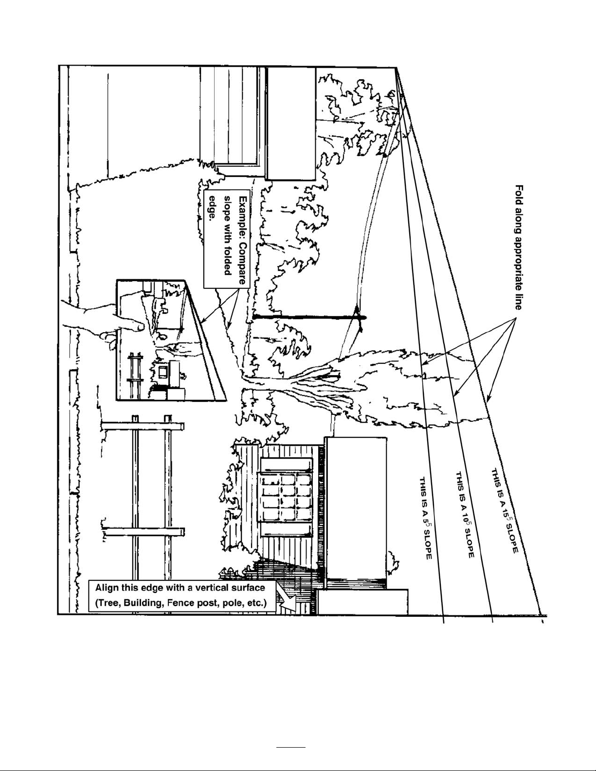
Slope Char t .........................................8
Safety and Instr uctional Decals . . . . . . . . . . . . 9
Setup ................................................................ 13
1 R emo ving the Shipping
Brac k et and Shipping
W ashers ............................. 14
2 Installing the Handle
Assembly .......................... 14
3 Installing the Fuel T ank . . . . . . . . . . . . . . . . . . . 15
4 Installing the Control R ods . . . . . . . . . . . . . . 16
5 Install the Speed Control
R od ................................... 16
6 Installing the Hair pin Cotter Pins
and Spacers ....................... 17
7 Acti v ating the Batter y . . . . . . . . . . . . . . . . . . . . . . 18
8 Chec king the Hy draulic Fluid and
Engine Oil Lev el . . . . . . . . . . . . . . . . 19
9 Setting Up the Hy dro
Linkag e ............................. 19
10 R eading the Man ual and Viewing
the Safety Video . . . . . . . . . . . . . . . . . 19
Product Ov er view ............................................. 21
Controls ............................................ 21
Operation .......................................................... 23
Adding Fuel ...................................... 23
Chec king the Engine Oil Lev el . . . . . . . . . . . 24
T hink Safety First .............................. 24
Operating the P arking Brak e . . . . . . . . . . . . . . 24
Star ting and Stopping the
Engine .............................. 25
Operating the Neutral Loc ks . . . . . . . . . . . . . . 26
Operating the Mo w er Blade
Control (PTO) ................... 26
T he Safety Interloc k System . . . . . . . . . . . . . . . 27
Dri ving the Mac hine F orw ard and
Bac kw ard .......................... 28
Bringing the Mac hine to Neutral
P osition ............................. 28
Stopping the Mac hine ........................ 28
Pushing the Mac hine b y Hand . . . . . . . . . . . . 29
T ranspor ting Mac hines . . . . . . . . . . . . . . . . . . . . . . 29
Using the Side Disc harg e . . . . . . . . . . . . . . . . . . . 29
Adjusting the Height-of-Cut . . . . . . . . . . . . . . 30
Adjusting the Gag e W heels . . . . . . . . . . . . . . . . 30
Adjusting the Handle Height . . . . . . . . . . . . . . 31
Maintenance ...................................................... 33
R ecommended Maintenance
Sc hedule(s) ............................... 33
Lubrication ................................................ 33
Ho w to Grease .................................. 33
W here to Add Grease ........................ 34
Lubricating the Caster
Bearings ............................ 34
Greasing the PTO Dri v e Belt Idler
and Dec k Belt Idler . . . . . . . . . . . . 34
Engine Maintenance .................................. 35
Ser vicing the Air Cleaner . . . . . . . . . . . . . . . . . . . 35
Ser vicing the Engine Oil . . . . . . . . . . . . . . . . . . . . 36
Ser vicing the Spark Plugs . . . . . . . . . . . . . . . . . . . 37
Fuel System Maintenance .......................... 38
Ser vicing the Fuel T ank . . . . . . . . . . . . . . . . . . . . . . 38
Ser vicing the Fuel Filter . . . . . . . . . . . . . . . . . . . . . 39
Electrical System Maintenance . . . . . . . . . . . . . . . . . . . 39
Ser vicing the Batter y .......................... 39
Ser vicing the Fuses ............................ 42
Dri v e System Maintenance . . . . . . . . . . . . . . . . . . . . . . . . . 42
Adjusting the Speed Control
Linkag e ............................. 42
© 2005—The Toro® Company8111 Lyndale Avenue SouthBloomington, MN 55420
2
Contact us at www.Toro.com.
Printed in the USA.All Rights Reserved

T emporar y Neutral Stud
Adjustment ....................... 44
Adjusting the Hy dro Control
Linkag es ............................ 44
Adjusting the Neutral Stud . . . . . . . . . . . . . . . . . 46
Adjusting the Control R od . . . . . . . . . . . . . . . . . 47
Adjusting the T rac king . . . . . . . . . . . . . . . . . . . . . . 48
Chec king the Tire Pressure . . . . . . . . . . . . . . . . . 48
R e placing the Caster W heel F ork
Bushings ........................... 49
Ser vicing the Caster W heel and
Bearings ............................ 50
Adjusting the Electric Clutc h . . . . . . . . . . . . . 50
Cooling System Maintenance . . . . . . . . . . . . . . . . . . . . . 51
Cleaning the Air Intak e Screen . . . . . . . . . . . 51
Brak e Maintenance .................................... 51
Ser vicing the Brak e ............................ 51
Belt Maintenance ....................................... 52
R e placing the Mo w er Belt . . . . . . . . . . . . . . . . . . 52
R e placing the PTO Dri v e Belt . . . . . . . . . . . . 52
Hy draulic System Maintenance . . . . . . . . . . . . . . . . . . 53
Ser vicing the Hy draulic
System ............................... 53
Mo w er Dec k Maintenance ......................... 55
Ser vicing the Cutting Blades . . . . . . . . . . . . . . . 55
Cor recting the Mo w er Quality of
Cut .................................... 57
F rame Set Up .................................... 58
Chec king the Mo w er Dec k
F ront-to-R ear Pitc h . . . . . . . . . . . 59
Changing the Dec k F ront-to-R ear
Pitc h .................................. 60
Chec king the Dec k Side-to-Side
Lev eling ............................ 60
Changing the Side-to-Side
Lev eling ............................ 60
Matc hing Height of Cut . . . . . . . . . . . . . . . . . . . . . 61
R e placing the Grass Deflector . . . . . . . . . . . . 61
Storag e .............................................................. 63
Cleaning and Storag e ......................... 63
T roubleshooting ................................................ 64
Sc hematics ........................................................ 67
Introduction
R ead this infor mation carefully to lear n ho w to
operate and maintain y our product properly and
to a v oid injur y and product damag e . Y ou are
responsible for operating the product properly
and safely .
Y ou ma y contact T oro directly at www .T oro .com
for product and accessor y infor mation, help
finding a dealer , or to register y our product.
W henev er y ou need ser vice , g en uine T oro par ts ,
or additional infor mation, contact an A uthorized
Ser vice Dealer or T oro Customer Ser vice and ha v e
the model and serial n umbers of y our product
ready . Figure 1 identifies the location of the model
and serial n umbers on the product. W rite the
n umbers in the space pro vided.
Figure 1
1. Location of the model and serial numbers
Model No.
Serial No.
T his man ual identifies potential hazards and has
safety messag es identified b y the follo wing w ords:
• Danger signals an extreme hazard that will
cause serious injur y or death if y ou do not
follo w the recommended precautions .
• W ar ning signals a hazard that may cause
serious injur y or death if y ou do not follo w the
recommended precautions .
• Caution signals a hazard that ma y cause minor
or moderate injur y if y ou do not follo w the
recommended precautions .
T his man ual uses tw o other w ords to highlight
infor mation. Impor tant calls attention to special
3

mec hanical infor mation and Note emphasizes
g eneral infor mation w or th y of special attention.
4

Safety
Note: T he addition of attac hments made b y
other man ufacturers that do not meet American
National Standards Institute cer tification will cause
noncompliance of this mac hine .
Improper use or maintenance b y the operator or
o wner can result in injur y . T o reduce the potential
for injur y , comply with these safety instr uctions
and alw a ys pa y attention to the safety aler t symbol
, whic h means CA UTION , W ARNING , or
D ANGER-“personal safety instr uction." F ailure
to comply with the instr uction ma y result in
personal injur y or death.
Safe Operating Practices
T he follo wing instr uctions are from ANSI
standard B71.4-2004.
Training
•R ead the Operator’ s Man ual and other training
material. If the operator(s) or mec hanic(s) can
not read English it is the o wner’ s responsibility
to explain this material to them.
•Become familiar with the safe operation of the
equipment, operator controls , and safety signs .
•All operators and mec hanics should be trained.
T he o wner is responsible for training the users .
•Nev er let c hildren or untrained people operate
or ser vice the equipment. Local regulations
ma y restrict the ag e of the operator .
•T he o wner/user can prev ent and is responsible
for accidents or injuries occur ring to himself
or herself , other people or proper ty .
Preparation
•Ev aluate the ter rain to deter mine what
accessories and attac hments are needed to
properly and safely perfor m the job . Only use
accessories and attac hments appro v ed b y the
man ufacturer .
•W ear appropriate clothing including hard hat,
safety glasses and hearing protection. Long
hair , loose clothing or jew elr y ma y g et tangled
in mo ving par ts .
•Inspect the area where the equipment is to be
used and remo v e all objects suc h as roc ks , to ys
and wire whic h can be thro wn b y the mac hine .
•Use extra care when handling g asoline and
other fuels . T hey are flammable and v apors
are explosi v e .
– Use only an appro v ed container
– Nev er remo v e g as cap or add fuel with
engine r unning . Allo w engine to cool
before refueling . Do not smok e .
– Nev er refuel or drain the mac hine indoors .
•Chec k that operator’ s presence controls ,
safety switc hes and shields are attac hed and
functioning properly . Do not operate unless
they are functioning properly .
Operation
•Nev er r un an engine in an enclosed area.
•Only operate in g ood light, k ee ping a w a y from
holes and hidden hazards .
•Be sure all dri v es are in neutral and parking
brak e is eng ag ed before star ting engine . Only
star t engine from the operator’ s position.
•Be sure of y our footing while using this
mac hine , especially when bac king up . W alk,
don ’ t r un. Nev er operate on w et g rass .
R educed footing could cause slipping .
•Slo w do wn and use extra care on hillsides . Be
sure to tra v el side to side on hillsides . T urf
conditions can affect the mac hine’ s stability .
Use caution while operating near drop-offs .
•Slo w do wn and use caution when making tur ns
and when c hanging directions on slopes .
•Nev er raise dec k with the blades r unning .
•Nev er operate with the PTO shield, or other
guards not securely in place . Be sure all
interloc ks are attac hed, adjusted properly , and
functioning properly .
•Nev er operate with the disc harg e deflector
raised, remo v ed or altered, unless using a g rass
catc her .
•Do not c hang e the engine g o v er nor setting or
o v erspeed the engine .
•Stop on lev el g round, diseng ag e dri v es , eng ag e
parking brak e (if pro vided), shut off engine
before lea ving the operator’ s position for any
reason including emptying the catc hers or
unclog ging the c hute .
5

•Stop equipment and inspect blades after
striking objects or if an abnor mal vibration
occurs . Mak e necessar y re pairs before
resuming operations .
•K ee p hands and feet a w a y from the cutting
unit.
•Look behind and do wn before bac king up to
be sure of a clear path.
•K ee p pets and b ystanders a w a y .
•Slo w do wn and use caution when making tur ns
and crossing roads and sidew alks . Stop blades
if not mo wing .
•Be a w are of the mo w er disc harg e direction and
do not point it at any one .
•Do not operate the mo w er under the influence
of alcohol or dr ugs .
•Use care when loading or unloading the
mac hine into or from a trailer or tr uc k.
•Use care when approac hing blind cor ners ,
shr ubs , trees , or other objects that ma y obscure
vision.
Maintenance and storage
•Diseng ag e dri v es , set parking brak e , stop
engine and remo v e k ey or disconnect spark
plug wire . W ait for all mo v ement to stop
before adjusting, cleaning or re pairing .
•Clean g rass and debris from cutting unit,
dri v es , m ufflers , and engine to help prev ent
fires . Clean up oil or fuel spillag e .
•Let engine cool before storing and do not store
near flame .
•Shut off fuel while storing or transpor ting . Do
not store fuel near flames or drain indoors .
•P ark mac hine on lev el g round. Set parking
brak e . Nev er allo w untrained personnel to
ser vice mac hine .
•Use jac k stands to suppor t components when
required.
•Carefully release pressure from components
with stored energ y .
•Disconnect the batter y or remo v e spark plug
wire before making any re pairs . Disconnect
the neg ati v e ter minal first and the positi v e last.
R econnect the positi v e first and neg ati v e last.
•Use care when c hec king blades . W rap the
blade(s) or w ear glo v es , and use caution when
ser vicing them. Only re place blades . Nev er
straighten or w eld them.
•K ee p hands and feet a w a y from mo ving par ts .
If possible , do not mak e adjustments with the
engine r unning .
•K ee p all par ts in g ood w orking condition and
all hardw are tightened. R e place all w or n or
damag ed decals .
Toro Mower Safety
T he follo wing list contains safety infor mation
specific to T oro products and other safety
infor mation y ou m ust kno w .
T his product is capable of amputating hands and
feet and thro wing objects . Alw a ys follo w all safety
instr uctions to a v oid serious injur y or death.
T his product is designed for cutting and recycling
g rass or , when equipped with a g rass bag g er , for
catc hing cut g rass . Any use for pur poses other
than these could pro v e dang erous to user and
b ystanders .
General Operation
•Be sure the area is clear of other people before
mo wing . Stop the mac hine if any one enters
the area.
•Do not touc h equipment or attac hment par ts
whic h ma y be hot from operation. Allo w to
cool before attempting to maintain, adjust or
ser vice .
•Use only T oro-appro v ed attac hments .
W ar ranty ma y be v oided if used with
unappro v ed attac hments .
•Chec k carefully for o v erhead clearances (i.e .
branc hes , doorw a ys , electrical wires) before
operating under any objects and do not contact
them.
Slope Operation
All slopes and ramps require extra caution. If y ou
feel uneasy on a slope , do not mo w it.
•R emo v e obstacles suc h as roc ks , tree limbs , etc .
from the mo wing area.
•W atc h for holes , r uts or bumps . T all g rass can
hide obstacles .
•Use caution near drop-offs , ditc hes , or
embankments . T he mac hine could suddenly
6

tur n o v er if a wheel g oes o v er the edg e of a
cliff or ditc h, or if an edg e ca v es in.
•Use extra care with g rass catc hers or other
attac hments . T hese can c hang e the stability of
the mac hine .
•K ee p all mo v ement on slopes slo w and g radual.
Do not mak e sudden c hang es in speed or
direction.
•Mo w slopes side to side .
•Do not mo w slopes g reater than 15 deg rees .
Service
•Nev er store the mac hine or fuel container
inside where there is an open flame , suc h as
near a w ater heater or fur nace .
•K ee p n uts and bolts tight, especially the blade
attac hment bolts . K ee p equipment in g ood
condition.
•Nev er tamper with safety devices . Chec k safety
systems for proper operation before eac h use .
•Use only g en uine re placement par ts to ensure
that original standards are maintained.
•Chec k brak e operation frequently . Adjust and
ser vice as required.
7

Slope Chart
8

Safety and Instructional Decals
Safety decals and instr uctions are easily visible to the operator and are located near any
area of potential dang er . R e place any decal that is damag ed or lost.
1-523552
43-8480
66-1340
67-5360
68-8340
93-1122
95-2814
98-0776
9

98-4387
1. Warning—wear hearing protection.
Battery Symbols
Some or all of these symbols are on your battery
1. Explosion hazard 6. Keep bystanders a safedistance from the battery.2. No re, open ame, orsmoking.
7. Wear eye protection;
explosive gases can causeblindness and other injuries3. Caustic liquid/chemical
burn hazard
8. Battery acid can causeblindness or severe burns.4. Wear eye protection
9. Flush eyes immediately
with water and get medicalhelp fast.5. Read the Operator’s
Manual.
10. Contains lead; do notdiscard.
104-2838
104-8186
105-4109
105-4110
106-0699
Manufacturer’s Mark
1. Indicates the blade is identied as a part from the originalmachine manufacturer.
10

106-5532
106-0635
106-5513
11

106-5516
1. Keep bystanders a safedistance from the machine.
6. Engine—stop
11. To place the machine inneutral, squeeze the drivelevers and rotate the neutrallocks backward.
16. Slow
2. Do not allow bystanders tobe hit by thrown objects.
7. Engine—run
12. To drive in reverse, squeezethe drive levers back to thegrips.
17. Neutral
3. Do not operate the mowerwith the deector up orremoved.
8. Engine—start
13. Power take-off (PTO)
4. Stop the engine and pick updebris before operating.
9. Hour meter
14. Fast
5. Mower can cut hands orfeet.
10. To drive forward, rotatethe neutral locks forwardand slowly release the drivelevers.
15. Continuous variable setting
106-5501
1. Choke
2. Fast
3. Continuous variable setting 4. Slow
12

Setup
Loose Parts
Use the chart below to verify that all parts have been shipped.
Step
Description
Qty.
Use
1
No parts required
–
Remove the shipping bracket andshipping washers.
Handle assembly
1
Flanged bolt (3/8 x 1 inch)
2
Flanged bolt (3/8 x 1-1/4 inches)
22
Flange nut (3/8 inch)
4
Install the handle assembly.
Fuel tank with studs installed
1
Bolt (5/16 x 7/8 inch)
2
Lock nut (5/16 inch)
2
Washer (5/16 inch)
4
Hose clamp
1
Lock washer (5/16 inch)
23
Spring
2
Install the fuel tank.
Control rods
24
E-ring
2
Install the control rods.
Washer
15
Cotter pin
1
Install the speed control rod.
Hairpin cotter pin
26
Spacers 6
Install the hairpin cotter pins andspacers.
7
No parts required
–
Activate the battery.
8
No parts required
–
Check the engine oil and hydraulicuid level.
9
No parts required
–
Set up the hydro linkage.
Operator’s Manual
1
Engine Operator’s Manual
1
Parts Catalog
1
Safety Video/DVD
1
Registration Card
110
Oil drain hose
1
Read the Operator’s Manual andwatch the video before operatingthe machine.
Note: Deter mine the left and right sides of the mac hine from the nor mal operating position.
13

Step
1
Removing the ShippingBracket and ShippingWashers
No Parts Required
Procedure
1. R emo v e the center g ag e wheel n ut, 2 larg e
w ashers , angle brac k et, and 1 small w asher
( Figure 2 ). Discard the 2 larg e w ashers and the
angle brac k et.
Figure 2
1. Center Gage Wheels andSpacer
4. Angle bracket-discard
2. Nut
5. Small washer3. Large washer-discard
2. Install the center g ag e wheels with the
previously remo v ed bolt, spacer , small w asher ,
and n ut ( Figure 3 ).
Figure 3
1. Center Gage Wheels andSpacer
4. Washer
2. Nut 5. Spacer3. Bolt
Step
2
Installing the HandleAssembly
Parts needed for this step:
1
Handle assembly
2
Flanged bolt (3/8 x 1 inch)
2
Flanged bolt (3/8 x 1-1/4 inches)
4
Flange nut (3/8 inch)
Procedure
1. Align handle with upper mounting holes in
rear frame ( Figure 4 ).
2. Secure the handle at eac h upper mounting hole
with a flang e bolt (3/8 x 1-1/4 inc hes) and
flang e n ut (3/8 inc h) ( Figure 4 ).
3. Select the lo w position for the lo w er mounting
hole ( Figure 4 ).
4. Secure the handle at eac h lo w er mounting hole
with a flang e bolt (3/8 x 1 inc h) and flang e n ut
(3/8 inc h) ( Figure 4 ).
Note: T he handle position can be adjusted to
matc h the operator’ s height preference .
14

Figure 4
1. Upper handle 6. Lower mounting holes2. Rear frame
7. Low position3. Flange nut, 3/8 inch 8. High position4. Flange bolt, 3/8 x 1 inch 9. Flange bolt, 3/8 x 1–1/4inch5. Upper mounting hole
Note: Install the handle assembly before the
fuel tank.
Step
3
Installing the Fuel Tank
Parts needed for this step:
1
Fuel tank with studs installed
2
Bolt (5/16 x 7/8 inch)
2
Lock nut (5/16 inch)
4
Washer (5/16 inch)
1
Hose clamp
2
Lock washer (5/16 inch)
2
Spring
Procedure
1. Align fuel tank with the top of the rear frame
( Figure 7 ).
2. Push the fuel line through the g rommet and
hole in the h y draulic oil filter brac k et ( Figure 5 ).
Figure 5
1. Fuel line 3. Hydraulic oil lter bracket2. Grommet and hole 4. Brake handle
Note: R emo v e the plastic cap from the fuel
fitting before installing the fuel line .
3. Push the fuel line onto the fuel tank connection
and secure it with the hose clamp that is on
the fuel line ( Figure 6 ).
Note: T o ease assembly of the fuel line to the
fuel tank connection, apply a light lubricant,
suc h as WD-40
®
to the end of the fuel line .
Figure 6
1. Bolt, 5/16 x 7/8 inch 4. Stud2. Lock washer, 5/16 inch
5. Spring3. Washer, 5/16 inch 6. Locknut
4. Secure the right side of the fuel tank to the
rear frame with 2 bolts (5/16 x 7/8 inc h), loc k
w ashers (5/16 inc h) and w ashers (5/16 inc h)
( Figure 7 ).
5. Secure the left side of the fuel tank to the rear
frame with w ashers (5/16 inc h), springs and
loc kn uts (5/16 inc h) ( Figure 7 ).
Note: Tighten left side of the fuel tank until
it is completely tight and then unscrew the
loc kn ut one full tur n. T his will allo w the spring
to w ork.
15

Figure 7
1. Bolt (5/8 x 7/8 inch)
5. Locknut2. Washer (5/8 inch)
6. Hose clamp3. Lock washer (5/8 inch)
7. Fuel tank connection4. Spring
Step
4
Installing the Control Rods
Parts needed for this step:
2
Control rods
2
E-ring
Procedure
1. F or a star ting point, mak e sure the rod fittings
are threaded appro ximately 2-1/2 inc hes (63
mm) onto the control rods ( Figure 8 )..
2. Install the control rod fittings into the control
ar m and secure them with E-rings ( Figure 8 ).
Figure 8
1. Control rod
4. E-ring2. Rod tting 5. Control arm3. 2–1/2 inch (63.5 mm) fromthe bottom
3. Place the clevis pin into the control rod, dri v e
lev er and neutral loc k ( Figure 9 ).
4. Install the hair pin cotter betw een the dri v e
lev ers and the neutral loc ks and into the clevis
pins ( Figure 9 ).
Figure 9
1. Control rod 5. Left handle shown2. Clevis pin 6. Neutral lock3. Drive lever
7. Hairpin cotter pin4. Operator Presence Controllever (OPC)
16

Step
5
Install the Speed ControlRod
Parts needed for this step:
1
Washer
1
Cotter pin
Procedure
Install the swi v el into the speed control crank and
secure it with a w asher and cotter pin ( Figure 10 ).
Note: If necessar y , mo v e the speed control lev er
until the swi v el will g o into the speed control
crank.
Figure 10
1. Speed control rod 4. Speed control crank2. Swivel
5. Cotter pin3. Nut
6. Washer
Step
6
Installing the Hairpin CotterPins and Spacers
Parts needed for this step:
2
Hairpin cotter pin
6 Spacers
Procedure
Store un used height-of-cut spacers on posts and
retain them b y a hair pin cotter .
Note: Mak e sure there is at least one spacer used
on eac h height-of-cut post.
1. R emo v e the existing rear hair pin cotter pins
from the rear height-of-cut posts ( Figure 11 ).
2. Install a spacer onto both rear height-of-cut
posts and install the hair pin cotter pins
( Figure 11 ).
Figure 11
1. Hairpin cotter
3. Height-of-cut post (rearshown)2. Spacer
3. Install a spacer onto both front height-of-cut
posts and install the hair pin cotter pins .
4. On the opposite side of the m uffler ,
install un used spacers onto front and rear
height-of-cut pins and inser t the hair pin cotter
pins ( Figure 12 ).
17

Figure 12
1. Hairpin cotter
3. Height-of-cut post (frontshown)2. Unused spacers
Step
7
Activating the Battery
No Parts Required
Procedure
Bulk electrolyte with 1.265 specific g ra vity m ust be
purc hased from a local batter y supply outlet.
Warning
CALIFORNIA
Pr oposition 65 W ar ning
Batter y posts, ter minals, and r elated
accessories contain lead and lead
compounds, chemicals kno wn to the State of
Calif or nia to cause cancer and r epr oducti v e
har m. W ash hands after handling .
Batter y electr ol yte contains sulfuric acid
which is a deadl y poison and causes sev er e
bur ns.
Do not drink electr ol yte and a v oid contact
with skin, ey es or clothing . W ear safety
g lasses to shield y our ey es and r ub ber g lo v es
to pr otect y our hands.
Fill the batter y wher e clean w ater is al w ays
a v aila ble f or flushing the skin.
F ollo w all instr uctions and compl y with all
safety messa ges on the electr ol yte container .
1. R emo v e the batter y from the mac hine . R efer
to R emo ving the Batter y .
2. Clean the top of the batter y with a paper to w el.
Note: Nev er fill the batter y with electrolyte
while the batter y is installed on the mac hine .
Electrolyte can be spilled on other par ts and
cause cor rosion.
3. R emo v e the v ent caps from the batter y
( Figure 13 ).
4. Slo wly pour electrolyte into eac h batter y cell
until the lev el is up to the upper line on the
batter y case .
Important: Do not o v erfill the batter y
because electr ol yte (sulfuric acid) can
cause sev er e cor r osion and dama ge to the
chassis.
5. W ait fiv e to ten min utes after filling the batter y
cells . Add electrolyte , if necessar y , until the
electrolyte lev el is up to the upper line on the
batter y case .
18

Figure 13
1. Fill caps 3. Lower line2. Upper line
6. Install the batter y fill caps ( Figure 13 ).
Charging the batter y pr oduces gasses
that can explode and cause serious injur y .
• K eep cigar ettes, spar ks and flames
a w ay fr om the batter y .
• Mak e sur e the ignition s witch is of f.
• V entilate when charging or using the
batter y in an enclosed space.
7. Mak e sure the v ent caps are installed in the
batter y . Charg e the batter y . R efer to Charging
the Batter y .
8. Install the batter y in the mac hine and connect
the batter y cables . R efer to Installing the
Batter y .
Important: Do not r un the machine
with the batter y disconnected; electrical
dama ge may occur to the engine.
Step
8
Checking the HydraulicFluid and Engine Oil Level
No Parts Required
Procedure
Before y ou star t the engine do the follo wing:
•c hec k the oil lev el in the engine crankcase;
refer to Chec king the Engine Oil Lev el.
•c hec k the h y draulic fluid lev el in the engine
crankcase; refer to Chec king Hy draulic the
Fluid Lev el.
Step
9
Setting Up the HydroLinkage
No Parts Required
Procedure
Chec k the follo wing adjustments when the
mac hine is first set up and adjust only as needed.
Do them in the order that they are listed here .
1. Chec k the speed control linkag e; refer to
Adjusting the Speed Control Linkag e .
2. Chec k the temporar y neutral stud adjustment;
refer to T emporar y Neutral Stud Adjustment
3. Chec k the h y dro control linkag es; refer to
Adjusting the Hy dro Control Linkag es .
4. Chec k the neutral stud; refer to Adjusting the
Neutral Stud.
5. Chec k the control rods; refer to Adjusting the
Control R ods .
6. Chec king the trac king; refer to Adjusting the
T rac king .
19

Step
10
Reading the Manual andViewing the Safety Video
Parts needed for this step:
1
Operator’s Manual
1
Engine Operator’s Manual
1
Parts Catalog
1
Safety Video/DVD
1
Registration Card
1
Oil drain hose
Procedure
•R ead the Operator’ s Manual and Engine Operator’ s
Manual .
•View the safety video .
•Fill out the registration card.
•Use the oil drain hose when c hanging the
engine oil.
20
Other manuals for ProLine 30441
1
Table of contents
Other Toro Mower manuals