Toro GreensPro 1260 User manual
FormNo.3429-810RevA
GreensPro™1260GreensRoller
ModelNo.44913—SerialNo.404680001andUp
Registeratwww.Toro.com.
OriginalInstructions(EN)*3429-810*A
ThisproductcomplieswithallrelevantEuropean
directives;fordetails,pleaseseetheseparateproduct
specicDeclarationofConformity(DOC)sheet.
ItisaviolationofCaliforniaPublicResourceCode
Section4442or4443touseoroperatetheengineon
anyforest-covered,brush-covered,orgrass-covered
landunlesstheengineisequippedwithaspark
arrester,asdenedinSection4442,maintainedin
effectiveworkingorderortheengineisconstructed,
equipped,andmaintainedforthepreventionofre.
WARNING
CALIFORNIA
Proposition65Warning
Theengineexhaustfromthisproduct
containschemicalsknowntotheStateof
Californiatocausecancer,birthdefects,
orotherreproductiveharm.
Useofthisproductmaycauseexposure
tochemicalsknowntotheStateof
Californiatocausecancer,birthdefects,
orotherreproductiveharm.
Introduction
Thismachineisaride-ongreensrollerintendedfor
usebyprofessional,hiredoperatorsincommercial
applications.Itisprimarilydesignedforrollinggreens,
tenniscourts,andotherneturfsurfacesinparks,golf
courses,sportselds,andoncommercialgrounds.
Usingthisproductforpurposesotherthanitsintended
usecouldprovedangeroustoyouandbystanders.
Readthisinformationcarefullytolearnhowtooperate
andmaintainyourproductproperlyandtoavoid
injuryandproductdamage.Youareresponsiblefor
operatingtheproductproperlyandsafely.
Visitwww.Toro.comforproductsafetyandoperation
trainingmaterials,accessoryinformation,helpnding
adealer,ortoregisteryourproduct.
Wheneveryouneedservice,genuineToroparts,or
additionalinformation,contactanAuthorizedService
DealerorToroCustomerServiceandhavethemodel
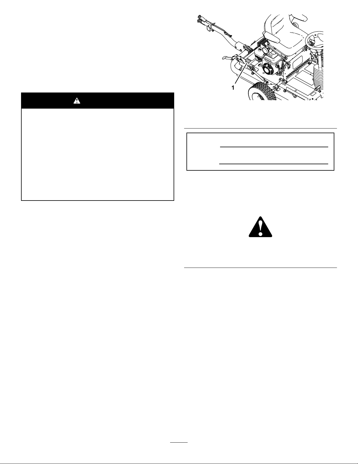
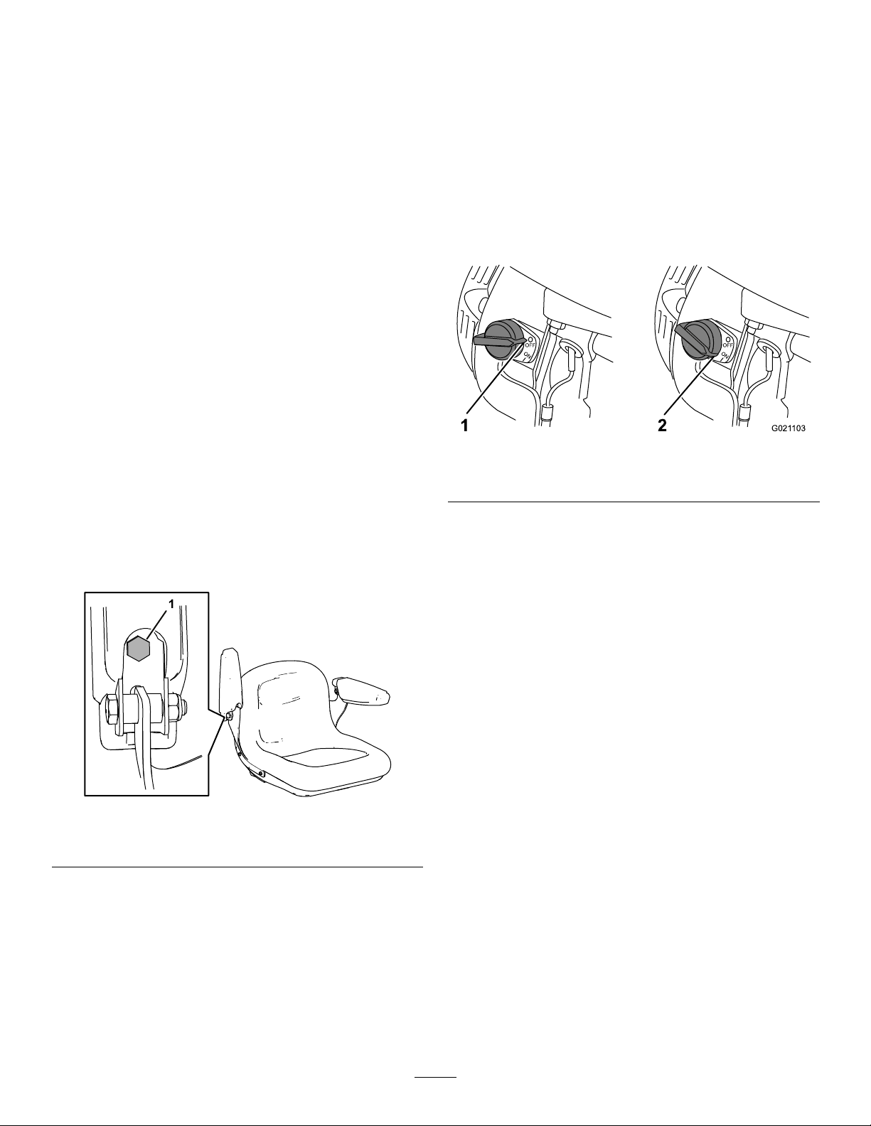
andserialnumbersofyourproductready.Figure1
identiesthelocationofthemodelandserialnumbers
ontheproduct.Writethenumbersinthespace
provided.
g279976
Figure1
1.Locationofthemodelandserialnumbers
ModelNo.
SerialNo.
Thismanualidentiespotentialhazardsandhas
safetymessagesidentiedbythesafety-alertsymbol
(Figure2),whichsignalsahazardthatmaycause
seriousinjuryordeathifyoudonotfollowthe
recommendedprecautions.
g000502
Figure2
Safety-alertsymbol
Thismanualuses2wordstohighlightinformation.
Importantcallsattentiontospecialmechanical
informationandNoteemphasizesgeneralinformation
worthyofspecialattention.
©2019—TheToro®Company
8111LyndaleAvenueSouth
Bloomington,MN554202
Contactusatwww.Toro.com.
PrintedintheUK
AllRightsReserved

Contents
Safety.......................................................................4
GeneralSafety...................................................4
SafetyandInstructionalDecals..........................4
Setup........................................................................7
1InstallingtheTransportWheels........................8
2InstallingtheHitchAssembly...........................8
3RemovingtheMachinefromthe
Pallet.............................................................10
4LubricatingtheMachine.................................10
ProductOverview....................................................11
Controls............................................................11
EngineControls............................................12
Specications..................................................13
Attachments/Accessories.................................13
BeforeOperation.................................................14
BeforeOperationSafety...................................14
PreparingtoUsetheMachine...........................14
FuelSpecication.............................................14
FillingtheFuelTank..........................................15
DuringOperation.................................................15
DuringOperationSafety...................................15
StartingtheEngine...........................................16
ShuttingOfftheEngine.....................................16
TransportingtheMachine.................................16
OperatingtheMachine.....................................19
OperatingTips.................................................19
AfterOperation....................................................19
AfterOperationSafety......................................19
HaulingtheMachine.........................................19
Maintenance...........................................................20
MaintenanceSafety..........................................20
RecommendedMaintenanceSchedule(s)...........20
NotationforAreasofConcern...........................21
DailyMaintenanceChecklist.............................21
Pre-MaintenanceProcedures..............................22
PreparingforMaintenance...............................22
RaisingtheOperator’sSeat..............................22
LoweringtheOperator’sSeat...........................23
Lubrication..........................................................23
LubricatingtheDrive-RollerBearing.................23
EngineMaintenance...........................................24
EngineSafety...................................................24
EngineOilSpecication....................................24
CheckingtheEngine-OilLevel..........................24
ChangingtheEngineOil...................................24
CheckingtheAir-FilterElements.......................26
ServicingtheAirCleaner..................................27
ServicingtheSparkPlug...................................27
CheckingandAdjustingtheValve
Clearance.....................................................28
FuelSystemMaintenance...................................28
CleaningtheSedimentCup..............................28
ElectricalSystemMaintenance...........................29
CheckingtheSafety-InterlockSystem..............29
BrakeMaintenance.............................................29
CheckingtheParkingBrake.............................29
AdjustingtheParkingBrake..............................29
HydraulicSystemMaintenance...........................30
HydraulicSystemSafety...................................30
CheckingtheHydraulicHosesand
Fittings..........................................................30
HydraulicFluidSpecication.............................31
CheckingtheHydraulic-FluidLevel...................31
ChangingtheHydraulicFluidand
Filter..............................................................32
ChassisMaintenance...........................................34
CheckingtheTireAirPressure..........................34
CheckingtheMachineforLoose
Hardware......................................................34
Cleaning..............................................................34
CleaningtheMachine.......................................34
Storage...................................................................35
PreparingtheMachineforShort-Term
Storage.........................................................35
PreparingtheMachineforLong-Term
Storage.........................................................35
StoringtheMachine..........................................35
3

Safety
Thismachinehasbeendesignedinaccordancewith
ENISO12100:2010andANSIB71.4-2017.
Important:ForCErequiredregulatorydata,refer
totheDeclarationofConformitysuppliedwith
themachine.
GeneralSafety
Thisproductiscapableofcausingpersonalinjury.
Alwaysfollowallsafetyinstructionstoavoidserious
personalinjury.
•Readandunderstandthecontentsofthis
Operator’sManualbeforestartingtheengine.
•Useyourfullattentionwhileoperatingthe
machine.Donotengageinanyactivitythat
causesdistractions;otherwise,injuryorproperty
damagemayoccur.
•Donotputyourhandsorfeetnearmoving
componentsofthemachine.
•Donotoperatethemachinewithoutallguards
andothersafetyprotectivedevicesinplaceand
workingonthemachine.
•Shutoffthemachine,removethekey(ifequipped),
andwaitforallmovementtostopbeforeyouleave
theoperator’sposition.Allowthemachinetocool
beforeadjusting,servicing,cleaning,orstoringit.
Improperlyusingormaintainingthismachinecan
resultininjury.Toreducethepotentialforinjury,
complywiththesesafetyinstructionsandalways
payattentiontothesafety-alertsymbol,which
meansCaution,Warning,orDanger—personalsafety
instruction.Failuretocomplywiththeseinstructions
mayresultinpersonalinjuryordeath.
SafetyandInstructionalDecals
Safetydecalsandinstructionsareeasilyvisibletotheoperatorandarelocatednearanyarea
ofpotentialdanger.Replaceanydecalthatisdamagedormissing.
decal120-0627
120-0627
1.Cutting/dismembermenthazard,fan—stayawayfrom
movingparts,keepallguardsandshieldsinplace.
decal127-5885
127-5885
1.Hitchunlock—1)push
downonthelatch;2)pull
outthehitch.
2.ReadtheOperator's
Manual.
decal130-8322
130-8322
1.Useonlygasolinethat
contains10%ethanolby
volume(E10)orless.
3.Donotusegasolinethat
containsmorethan10%
ethanolbyvolume(E10).
2.ReadtheOperator's
Manual.
decal131-0440
131-0440
1.Parkingbrake—engage2.Parkingbrake—disengage
4
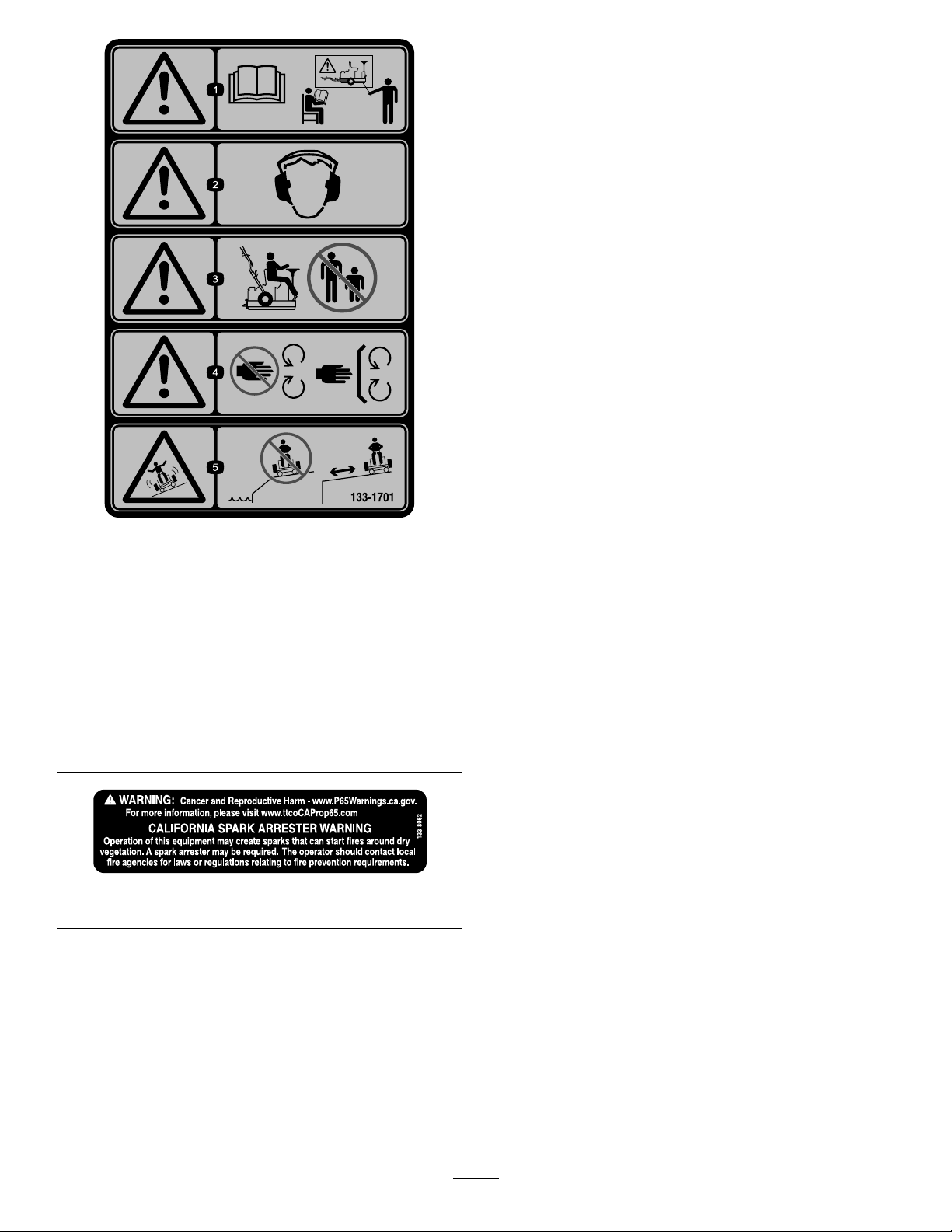
decal133-1701
133-1701
1.Warning—readthe
Operator'sManual;do
notoperatethemachine
unlessyouhavereceived
training.
4.Warning—keepaway
frommovingparts;keep
allguardsandshieldsin
place.
2.Warning—wearhearing
protection.
5.Tippinghazard—donot
operatethemachinenear
water;stayawayfrom
embankmentsordropoffs.
3.Warning—keep
bystandersawayfrom
themachine.
decal133-8062
133-8062
5
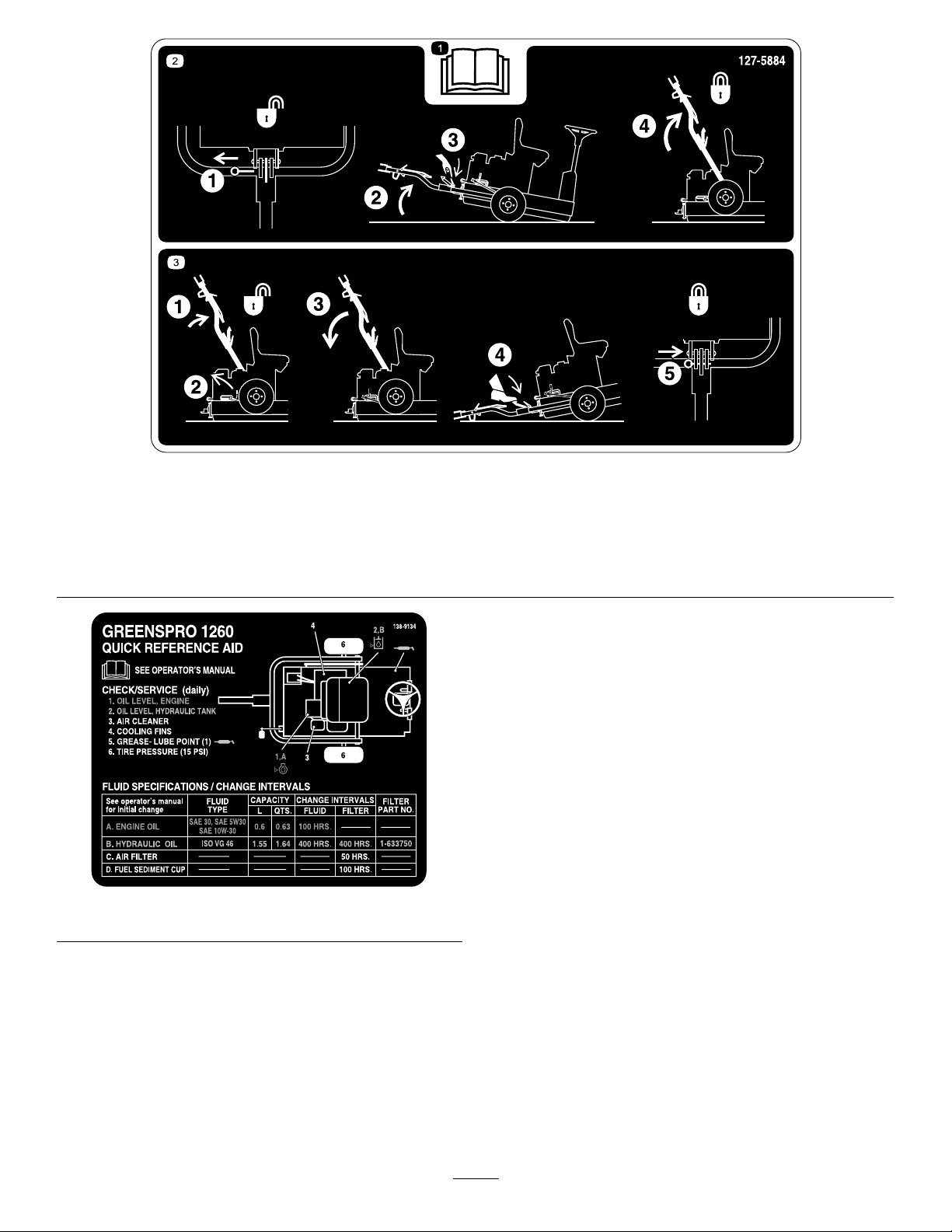
decal127-5884
127-5884
1.ReadtheOperator’sManual.3.1)Pushthehitchup;2)Releasethelatchlever;3)Pullthe
hitchdown;4)Steponthefootpedaluntilthehitchsnapsinto
place;5)Insertthelockpin.
2.1)Pullthelockpin;2)Tipthemachineup;3)Unlatchthe
hitch;4)Raisethehitchuntiltheleverlatchlocksintheslide.
decal138-9134
138-9134
6

Setup
LooseParts
Usethechartbelowtoverifythatallpartshavebeenshipped.
ProcedureDescriptionQty.Use
1Transportwheel2Installthetransportwheels.
Lockbracket1
Bolt(M10x30mm)4
Lockwasher(M10)4
Washer(M10)6
Nut(M10)4
Hitchassembly1
Bolt(M10x100mm)1
Locknut(M10)1
Bolt(M12x100mm)1
Washer(M12)2
Locknut(M12)1
2
Spacerwasher(whenapplicable)2
Installthehitchassembly.
3Nopartsrequired–Removethemachinefromthepallet.
4Lubricants(notincluded)–Lubricatethemachine.
MediaandAdditionalParts
DescriptionQty.Use
Operator’sManual1
Engineowner’smanual1Readthemanualsbeforeoperatingthemachine.
CerticateofCompliance1ThecerticateisrequiredforEuropeanCEcompliance.
7
1
InstallingtheTransport
Wheels
Partsneededforthisprocedure:
2Transportwheel
RemovingtheShippingBrackets
1.Removethelugnutssecuringthewheelhubsto
theshippingbracket(Figure3).
g279735
Figure3
1.Lugnut3.Shippingbracket
2.Lagbolt
2.Removetheotherlugnutthreadedontothe
wheel-hubstud(Figure3).
3.Removethelagboltsthatsecuretheshipping
bracketstothepallet,andremovethebracket
(Figure3).
4.Repeatsteps1through3fortheshipping
bracketattheothersideofthemachine.
InstallingtheWheels
1.Looselyassemblethe2transportwheelsonto
thewheelhubswiththelugnutsthatyou
removedinRemovingtheShippingBrackets
(page8).
Note:Youwilltorquethelugnutsattheendof
2InstallingtheHitchAssembly(page8).
2.Adjustthetireairpressureto103kPa(15psi).
2
InstallingtheHitch
Assembly
Partsneededforthisprocedure:
1Lockbracket
4Bolt(M10x30mm)
4Lockwasher(M10)
6Washer(M10)
4Nut(M10)
1Hitchassembly
1Bolt(M10x100mm)
1Locknut(M10)
1Bolt(M12x100mm)
2Washer(M12)
1Locknut(M12)
2Spacerwasher(whenapplicable)
Procedure
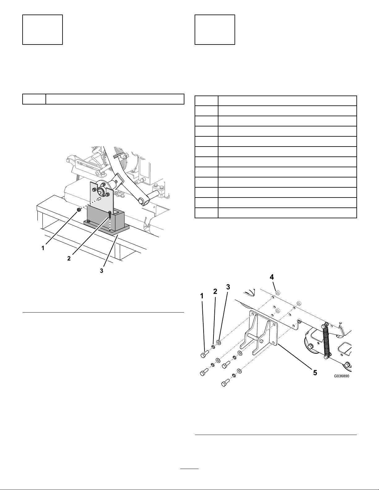
1.Installthelockbrackettotheframeofthe
machineasshowninFigure4.
Note:Torquethenutsto52N∙m(38ft-lb).
g036890
Figure4
1.Bolt—M10x30mm(4)4.Nut—M10(4)
2.Lockwasher—M10(4)5.Lockbracket
3.Washer—M10(4)
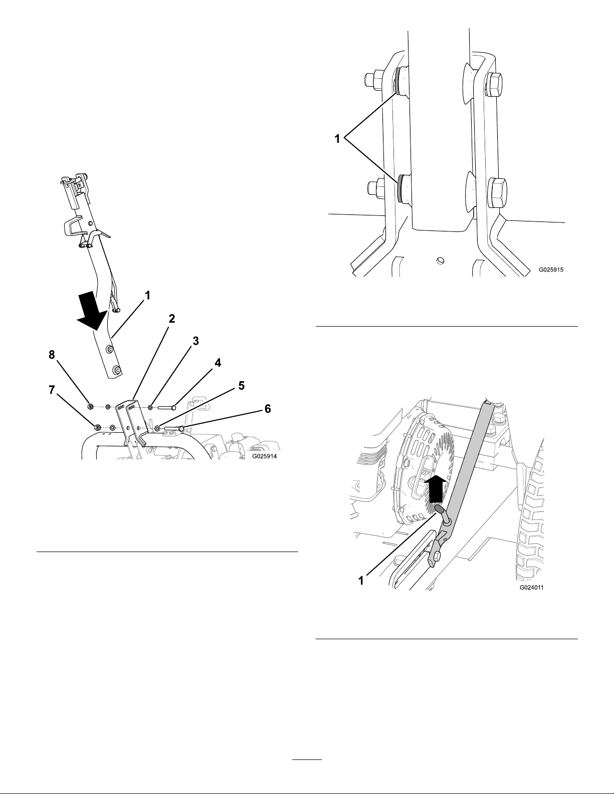
2.Securethehitchtothehitchpivotbracketwith
theappropriatehardware;refertoFigure5.
8
•Inthefrontholes,useabolt(M10x100
mm),2washers(M10),andalocknut(M10).
•Intherearholes,useabolt(M12x100mm),
2washers(M12),andalocknut(M12).
•Ifyourmachinehasathirdwasherincluded
witheachbolt,usethosewashersasspacers
betweenthehitchandtheinsideofthehitch
pivotbracket(Figure6).
Note:Usetheholesinthehitchpivotbracketto
matchthehitchheightofthetow-vehiclehitch.
g025914
Figure5
1.Hitch5.Washer—M12(2)
2.Hitchpivotbracket6.Bolt(M12)
3.Washer—M10(2)7.Locknut(M12)
4.Bolt(M10)8.Locknut(M10)
g025915
Figure6
1.Spacerwashers
3.Tightenthesmallboltto73N∙m(54ft-lb)and
thelargeboltto126N∙m(93ft-lb).
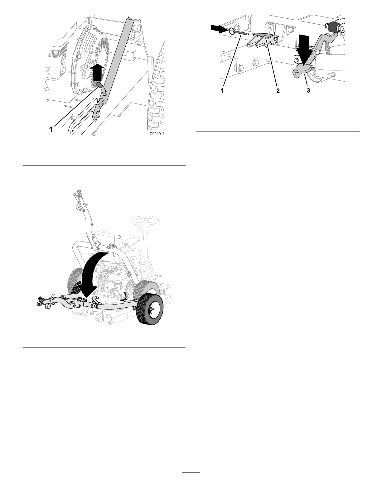
4.Pushuponthehitchassemblyuntilthelatch
leverisunlockedfromtheslidedetent(Figure7).
g024011
Figure7
1.Latchlever
5.Pullthehitchdown.
6.Ifinstalled,removethelockingpinfromthelatch
(Figure8).
9
g279746
Figure8
1.Lockingpin3.Hitchpedal
2.Latch
7.Steponthehitchpedaluntilthehitchlocksinto
place(Figure8).
8.Insertthelockingpinthroughtheholesinthe
latch(Figure8).
9.Torquethelugnutsonthetransportwheelsto
108N∙m(80ft-lb).
3
RemovingtheMachine
fromthePallet
NoPartsRequired
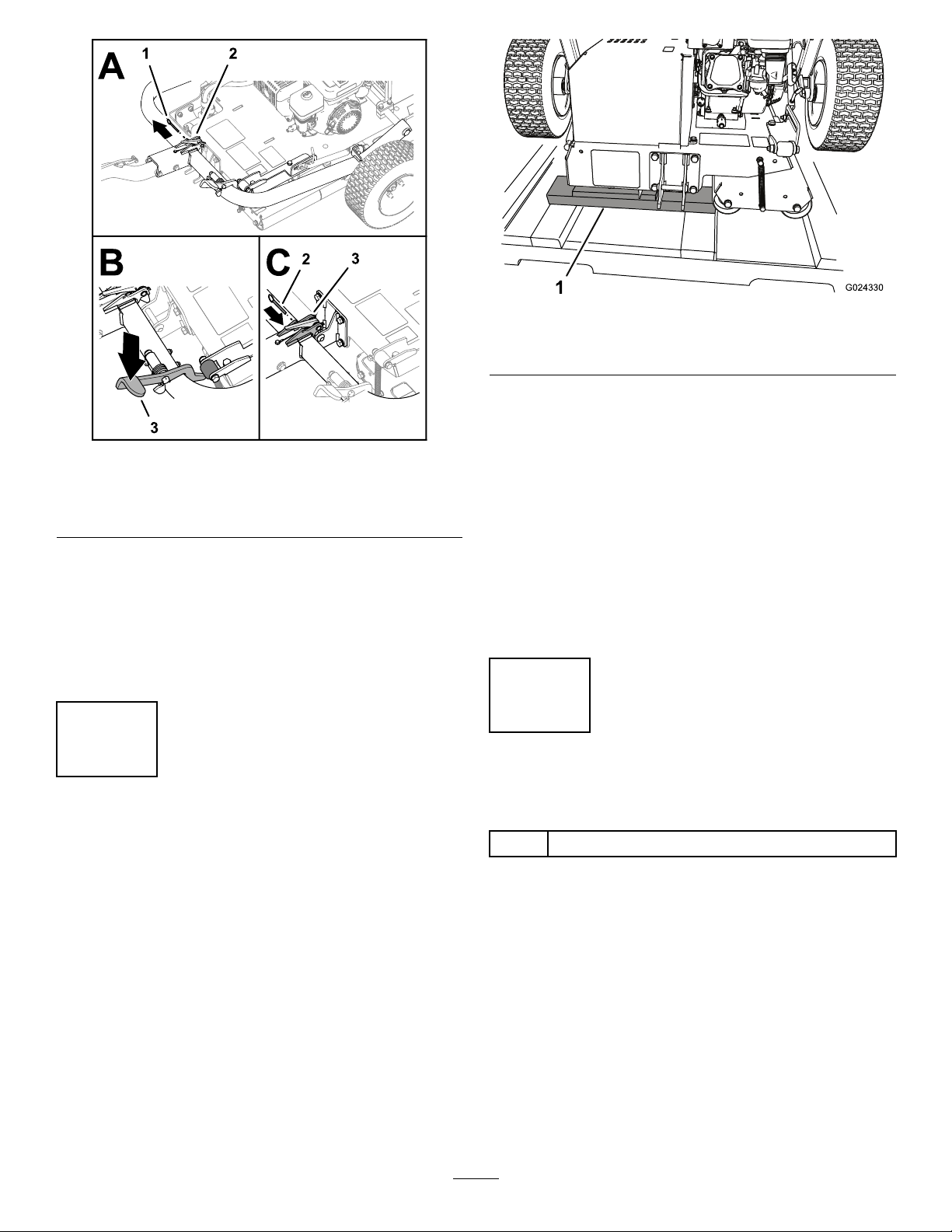
Procedure
1.Removethewoodblocksatthehitchendofthe
pallet.
g024330
Figure9
1.Woodblocks
2.Placesomewoodboardsonthegroundatthe
endofthepallet.
Note:Theheightofthewoodboardsshouldbe
slightlylowerthanthepallet.Youcanusepieces
removedfromthesidesand/orendsofthecrate.
3.Carefullyrollthemachineoffthepallet,ontothe
woodboards,andthentotheground.
Important:Ensurethattherollersdonot
contactthepalletasthemachinedropsto
theground.
4.Removeanyremainingpackaging.
4
LubricatingtheMachine
Partsneededforthisprocedure:
–Lubricants(notincluded)
Procedure
Beforeyouoperatethemachine,lubricateittoensure
properoperatingcharacteristics;refertoLubricating
theDrive-RollerBearing(page23).Failuretoproperly
lubricatethemachinewillresultinprematurefailure
ofcriticalparts.
10
ProductOverview
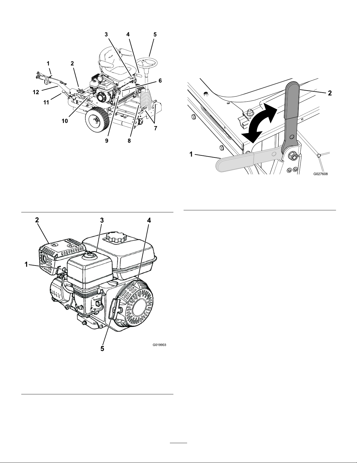
g279748
Figure10
1.Hitch-locklever7.Motionpedals
2.Hitchlatch8.Tilt-steeringpedal
3.Seat-adjustmentlever9.Hourmeter
4.Parkingbrake10.Latchlever
5.Steeringwheel11.Hitchpedal
6.Lightswitch12.Hitchassembly
g019903
Figure11
1.Sparkplug4.Recoilstarter
2.Mufer5.Recoil-starthandle
3.Aircleaner
Controls
ParkingBrake
Engagetheparkingbraketoallowthemachineto
start.T oengagetheparkingbrake(Figure12),pull
backontheparking-brakelever.Todisengageit,
pushtheleverforward.
g027608
Figure12
1.Parking
brake—disengaged
2.Parkingbrake—engaged
SteeringWheel
Turnthesteeringwheel(Figure10)clockwisetoturn
themachineintheforwarddirection.
Turnthesteeringwheelcounterclockwisetoturnthe
machineintherearwarddirection.
Note:Asthedirectionchangesattheendofevery
run,youwillneedtopracticewiththemachineto
becomeaccustomedtothesteering.
Thesteeringwheelcontrolstheangleofthesmoothing
rollers,whichinturnsteerthemachine.Theamount
thewheelcanbeturnedislimited,sotheturning
radiusofthemachineislarge.
Tilt-SteeringPedal
Totiltthesteeringwheeltowardyou,pressthefoot
pedal(Figure10)down,pullthesteeringtowertoward
youtothemostcomfortableposition,andreleasethe
pedal.
MotionPedals
Thefoot-operatedmotionpedals(Figure10),located
toeithersideofthebaseofthesteeringwheel,
controlthemotionofthedriveroller.Thepedalsare
connectedsothattheycannotbothbepresseddown
atthesametime,youcanpressonly1pedalata
11
time.Ifyoupressdowntherightpedal,themachine
movestotheright,andifyoupressdowntheleft
pedal,themachinemovestotheleft.Thefurtheryou
pressapedal,thefasteryourspeedinthatdirection.
Note:Cometoafullstopbeforechangingthe
directionofthemachine;donotabruptlychangethe
pedaldirection.Doingsooverstressesthetraction
driveline,resultinginprematurefailureofdrive-line
components.Actuatethepedalsslowlyandsmoothly
toavoidpotentialturfscufngdamageaswellas
drive-linecomponentdamage.
Whenoperatingthemachineonhills,ensurethat
thedriverollerisonthedownhillsideforadequate
traction.Failuretodosomayresultinturfdamage.
HitchAssembly
Usethehitchassembly(Figure10)totowthemachine
andtolower/raisethetransportwheels.
Seat-AdjustmentLever
Youcanmovetheseatforwardorbackward.Rotate
theseat-adjustmentlever(Figure10)upwardand
slidetheseatforwardorbackward,thenreleasethe
lever.
Armrest-AdjustmentBolts
Youcanadjusteacharmrestbyturningtherespective
adjustmentbolt(Figure13).
g279749
Figure13
1.Adjustmentbolt
LightSwitch
Usethelightswitchtoturnthelightsonandoff(Figure
10).
HourMeter
Thehourmeter(Figure10)indicatesthetotalhoursof
machineoperation.
EngineControls
Note:Refertoyourengineowner’smanualfor
additionalengine-controlinformation.
On/OffSwitch
TheOn/Offswitch(Figure14)allowstheoperatorof
themachinetostartandshutofftheengine.This
switchislocatedonthefrontoftheengine.Rotatethe
On/OffswitchtotheONpositiontostartandrunthe
engine.RotatetheOn/OffswitchtotheOFFposition
toshutofftheengine.
g021103
Figure14
1.OFFposition2.ONposition
ChokeLever
Thechokelever(Figure15)isrequiredwhenstarting
acoldengine.Beforepullingtherecoil-starthandle,
movethechokelevertotheCLOSEDposition.Once
theengineisrunning,movethechokelevertothe
OPENposition.Donotusethechokeiftheengineis
alreadywarmeduporiftheairtemperatureishigh.
12
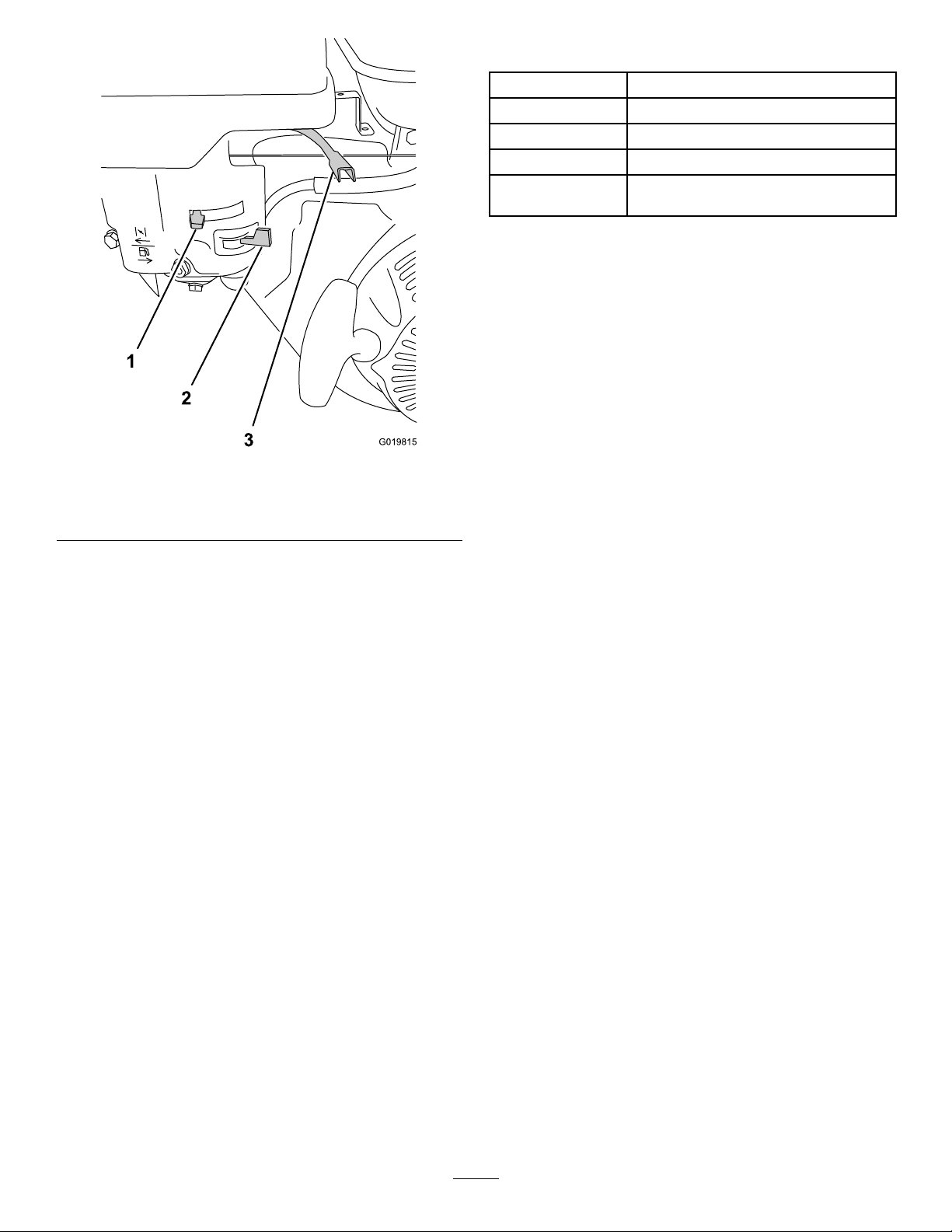
g019815
Figure15
1.Chokelever3.Throttlelever
2.Fuel-shutoffvalve
ThrottleLever
Thethrottlelever(Figure15)islocatednexttothe
chokecontrol;itcontrolsthespeedoftheengine
andthereforecontrolsthespeedofthemachine.For
bestrollingperformance,setthiscontroltotheFAST
position.
Fuel-ShutoffValve
Thefuel-shutoffvalve(Figure15)islocated
underneaththechokelever.Moveittotheopen
positionbeforeattemptingtostarttheengine.Once
youhavenishedusingthemachineandyouhave
turnedtheengineoff,movethefuel-shutoffvalveto
theCLOSEDposition.
Recoil-StartHandle
Tostarttheengine,pulltherecoil-starthandle(Figure
11)quicklytoturntheengineover.Thecontrolson
theenginedescribedabovemustallbesetcorrectly
fortheenginetostart.
Oil-LevelSwitch
Theoil-levelswitchislocatedinsidetheengine;it
preventstheenginefromrunningiftheoillevelfalls
belowthesafeoperatinglimit.
Specications
Weight308kg(679lb)
Length136cm(53.5inches)
Width122cm(48.0inches)
Height107cm(42.2inches)
Maximumground
speed
12.8km/h(8mph)@3600rpm
Attachments/Accessories
AselectionofT oroapprovedattachmentsand
accessoriesisavailableforusewiththemachine
toenhanceandexpanditscapabilities.Contact
yourAuthorizedServiceDealerorauthorizedT oro
distributororgotowww.T oro.comforalistofall
approvedattachmentsandaccessories.
Toensureoptimumperformanceandcontinuedsafety
certicationofthemachine,useonlygenuineToro
replacementpartsandaccessories.Replacement
partsandaccessoriesmadebyothermanufacturers
couldbedangerous,andsuchusecouldvoidthe
productwarranty.
13

Operation
BeforeOperation
BeforeOperationSafety
GeneralSafety
•Shutoffthemachineandwaitforallmovement
tostopbeforeyouleavetheoperator’sposition.
Allowthemachinetocoolbeforeadjusting,
servicing,cleaning,orstoringit.
•Neverallowchildrenoruntrainedpeopleto
operateorservicethemachine.Localregulations
mayrestricttheageoftheoperator.Theowner
isresponsiblefortrainingalloperatorsand
mechanics.
•Becomefamiliarwiththesafeoperationofthe
equipment,operatorcontrols,andsafetysigns.
•Knowhowtostopthemachineandenginequickly.
•Checkthatoperator-presencecontrols,safety
switches,andshieldsareattachedandfunctioning
properly.Donotoperatethemachineunlessthey
arefunctioningproperly.
•Beforeoperating,alwaysinspectthemachine
toensurethatthecomponentsandfasteners
areingoodworkingcondition.Replacewornor
damagedcomponentsandfasteners.
•Inspecttheareawhereyouwillusethemachine
andremoveallobjectsthatthemachinecould
throw.
FuelSafety
•Useextremecareinhandlingfuel.Itisammable
anditsvaporsareexplosive.
•Extinguishallcigarettes,cigars,pipes,andother
sourcesofignition.
•Useonlyanapprovedfuelcontainer.
•Donotremovethefuelcaporllthefueltank
whiletheengineisrunningorhot.
•Donotaddordrainthefuelinanenclosedspace.
•Donotstorethemachineorfuelcontainerwhere
thereisanopename,spark,orpilotlight,such
asonawaterheaterorotherappliance.
•Ifyouspillfuel,donotattempttostarttheengine;
avoidcreatinganysourceofignitionuntilthefuel
vaporshavedissipated.
PreparingtoUsethe
Machine
1.Clearanydebrisontopofandunderneaththe
machine.
2.Engagedtheparkingbrake.
3.Completethefollowingdailymaintenance
procedures:
•LubricatingtheDrive-RollerBearing(page
23)
•CheckingtheEngine-OilLevel(page24)
•CheckingtheAir-FilterElements(page26)
•CheckingtheSafety-InterlockSystem(page
29)
•CheckingtheParkingBrake(page29)
•CheckingtheHydraulicHosesandFittings
(page30)
•CheckingtheHydraulic-FluidLevel(page
31)
•CheckingtheTireAirPressure(page34)
•CheckingtheMachineforLooseHardware
(page34)
4.Ensurethatallguardsandcoversareinplace
andsecurelyattached.
5.Liftthetransportwheelsclearofthegroundand
ensurethattheylockinplace.
FuelSpecication
•Useunleaded(87pumpoctaneminimum)
gasoline.
•Forbestresults,useonlyclean,fresh(lessthan
30daysold),unleadedgasolinewithanoctane
ratingof87orhigher((R+M)/2ratingmethod).
•Ethanol:Gasolinewithupto10%ethanol
(gasohol)or15%MTBE(methyltertiarybutyl
ether)byvolumeisacceptable.EthanolandMTBE
arenotthesame.Gasolinewith15%ethanol
(E15)byvolumeisnotapprovedforuse.Never
usegasolinethatcontainsmorethan10%ethanol
byvolume,suchasE15(contains15%ethanol),
E20(contains20%ethanol),orE85(contains85%
ethanol).Usingunapprovedgasolinemaycause
performanceproblemsand/orenginedamage,
whichmaynotbecoveredunderwarranty.
•Donotusemethanolorgasolinecontaining
methanol.
•Donotstorefueleitherinthefueltankorfuel
containersoverthewinterunlessafuelstabilizer
isused
•Donotaddoiltogasoline.
14
FillingtheFuelTank
Fuel-TankCapacity:3.6L(0.95USgallons)
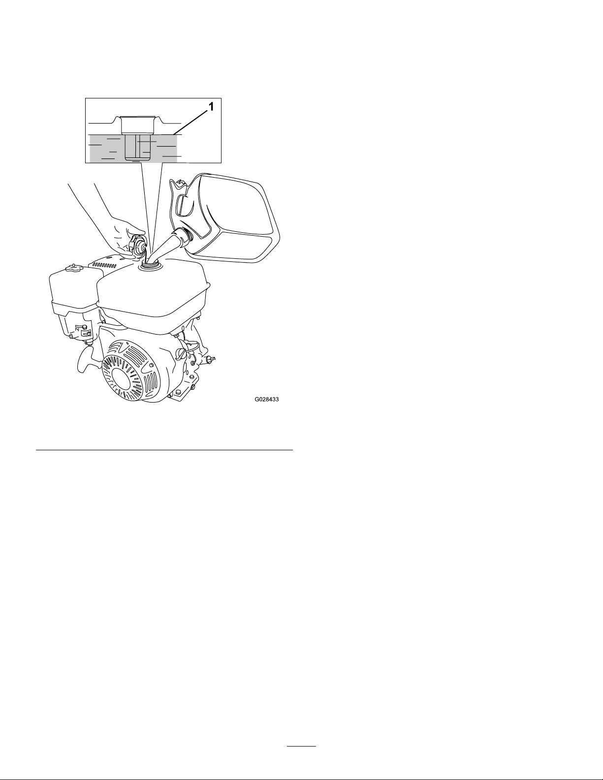
1.Cleanaroundthefuel-tankcapandremovethe
capfromthetank(Figure16).
g028433
Figure16
1.Maximumfuellevel
2.Fillthefueltanktoapproximately25mm(1inch)
belowthetopofthetankwiththespeciedfuel.
Theairspacebelowthetopofthetankallows
thefueltoexpand.
Important:Donotoverllthefueltank.
Addingmorethatthespeciedlevelresults
indamagetothevaporrecoverysystem,
leadingtoengineperformancefailure.This
isnotawarrantablefailureandrequires
fuel-tankcapreplacement.
3.Installthefuel-tankcapandwipeupanyspilled
fuel.
DuringOperation
Note:Determinetheleftandrightsidesofthe
machinefromthenormaloperatingposition.
DuringOperationSafety
GeneralSafety
•Theowner/operatorcanpreventandisresponsible
foraccidentsthatmaycausepersonalinjuryor
propertydamage.
•Wearappropriateclothing,includingeye
protection;longpants;substantial,slip-resistant
footwear;andhearingprotection.Tiebacklong
hairanddonotwearlooseclothingorloose
jewelry.
•Donotoperatethemachinewhileill,tired,or
undertheinuenceofalcoholordrugs.
•Useyourfullattentionwhileoperatingthe
machine.Donotengageinanyactivitythat
causesdistractions;otherwise,injuryorproperty
damagemayoccur.
•Keepbystandersandpetsoutoftheoperating
area.
•Nevercarrypassengersonthemachine.
•Operatethemachineonlyingoodvisibilitytoavoid
holesorhiddenhazards.
•Avoidoperatingonwetgrass.Reducedtraction
couldcausethemachinetoslide.
•Beforeyoustarttheengine,ensurethatalldrives
areinneutral,theparkingbrakeisengaged,and
youareintheoperatingposition.
•Lookbehindanddownbeforebackinguptobe
sureofaclearpath.
•Usecarewhenapproachingblindcorners,shrubs,
trees,orotherobjectsthatmayobscureyour
vision.
•Donotoperateneardrop-offs,ditches,or
embankments.Themachinecouldsuddenlyroll
overifanedgegivesway.
•Stopthemachine,engagetheparkingbrake,
andshutofftheengineinspecttheattachment
afterstrikinganobjectorifthereisanabnormal
vibrationinthemachine.Makeallnecessary
repairsbeforeresumingoperation.
•Slowdownandusecautionwhenmakingturns
andcrossingroadsandsidewalkswiththe
machine.Alwaysyieldtheright-of-way.
•Neverrunanengineinanareawhereexhaust
gassesareenclosed.
•Neverleavearunningmachineunattended.
•Beforeleavingtheoperatingposition,dothe
following:
–Parkthemachineonlevelground.
–Engagetheparkingbrake.
–Shutofftheengine.
–Waitforallmovingpartstostop.
15

•Donotoperatethemachinewhenthereistherisk
oflightning.
•Donotusethemachineasatowingvehicle.
•Useaccessories,attachments,andreplacement
partsapprovedbyTheT oro®Companyonly.
•Keephandsandfeetawayfromtherollers.
•Usecarewhenconnectinganddisconnectingthe
machinetoandfromthetowvehicle.
SlopeSafety
•Establishyourownproceduresandrulesfor
operatingonslopes.Theseproceduresmust
includesurveyingthesitetodeterminewhich
slopesaresafeformachineoperation.Always
usecommonsenseandgoodjudgmentwhen
performingthissurvey.
•Slopesareamajorfactorrelatedtolossofcontrol
androlloveraccidents,whichcanresultinsevere
injuryordeath.Theoperatorisresponsiblefor
safeslopeoperation.Operatingthemachineon
anysloperequiresextracaution.
•Operatethemachineatalowerspeedwhenyou
areonaslope.
•Ifyoufeeluneasyoperatingthemachineona
slope,donotdoit.
•Watchforholes,ruts,bumps,rocks,orother
hiddenobjects.Uneventerraincouldoverturnthe
machine.Tallgrasscanhideobstacles.
•Choosealowgroundspeedsothatyoudonot
needtostoporshiftwhileonaslope.
•Arollovercanoccuriftherollerslosetraction.
•Avoidoperatingthemachineonwetgrass.Rollers
maylosetraction,regardlessofwhetherthe
brakesareavailableandfunctioning.
•Avoidstarting,stopping,orturningthemachine
onaslope.
•Keepallmovementonslopesslowandgradual.
Donotsuddenlychangethespeedordirectionof
themachine.
StartingtheEngine
Note:Makesurethatthespark-plugwireis
connectedtothesparkplug.
1.EnsurethatthelightsswitchisintheOffposition.
2.Ensurethattheparkingbrakeisengagedand
thatthemotionpedalsareintheNEUTRAL
position.
3.TurntheOn/OffswitchtotheONposition.
4.Turnthefuel-shutoffvalvetotheOPENposition.
5.MovethechokelevertotheONpositionwhen
startingacoldengine.
Note:Thechokemaynotberequiredwhen
startingawarmengine.
6.MovethethrottlecontroltotheFASTposition.
7.Standattherearofthemachine,pullthe
recoil-starthandleoutuntilpositiveengagement
results;thenpullitvigorouslytostarttheengine.
Important:Donotpulltherecoilropeto
thelimitorletgoofthestarterhandlewhen
theropeispulledout,becausetherope
maybreakortherecoilassemblymaybe
damaged.
8.Whentheenginehasstarted,pushthechoke
levertotheOFFposition.
9.MovethethrottlelevertotheFASTposition,for
bestrollerperformance.
ShuttingOfftheEngine
1.Afteroperatingthemachine,returnthemotion
pedalstotheNEUTRALpositionandengagethe
parkingbrake.
2.Settheenginespeedtoidle,andallowittorun
for10to20seconds.
3.TurntheengineOn/OffswitchtotheOFF
position.
4.Turnthefuel-shutoffvalvetotheCLOSED
position.
5.SetthelightsswitchtotheOFFposition.
TransportingtheMachine
PreparingtoTransportthe
Machine
1.Drivethemachinetothetransportvehicle.
2.Engagetheparkingbrake.
3.Shutofftheengine;refertoShuttingOffthe
Engine(page16).
4.Ensurethatthefuel-shutoffvalvetotheCLOSED
position.
RaisingtheMachineontothe
TransportWheels
1.Pushuponthehitchassemblyuntilthelatch
leverisunlockedfromtheslidedetent(Figure
17).
16
g024011
Figure17
1.Latchlever
2.Liftthelatchleversothatitslidesfreely,andpull
thehitchdown.
g279826
Figure18
3.Steponthehitchpedaluntilthehitchlocksinto
place(Figure19).
g279795
Figure19
1.Lockingpin3.Hitchpedal
2.Latch
4.Insertthelockingpinthroughtheholesinthe
latch(Figure19).
5.Iftheyouaretransportingthemachine,connect
ittothetowvehicle;refertoConnectingthe
MachinetotheTowVehicle(page17).
ConnectingtheMachinetothe
TowVehicle
Pushdownonthehitch-lockleverwhileinsertingthe
hitchassemblyontothetow-vehiclehitch.Release
theleverwhenthehitchandthehitchassemblyare
aligned(Figure20).
Important:EnsurethattheleverreturnstotheUp
positionandthatthehitchandthehitchassembly
areengaged.
17
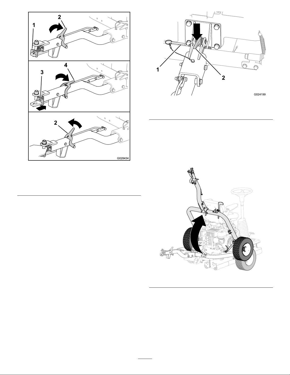
g028434
Figure20
1.Hitchassembly(forward)3.Hitchassembly
(backward)
2.Hitch-locklever(up)4.Hitch-locklever(down)
DisconnectingtheMachinefrom
theTowVehicle
Parkthemachineonlevelgroundandchockthe
wheels.
Pushdownonthehitch-lockleverwhileremoving
thehitchassemblyfromthetow-vehiclehitch(Figure
20).Releasethelatchwhenthehitchandthehitch
assemblyaredisengaged.
LowertheMachineontothe
Rollers
1.Ifthemachineisconnectedtoatowvehicle,
disconnectthemachinefromthetowvehicle;
refertoDisconnectingtheMachinefromtheT ow
Vehicle(page18).
2.Removethelockingpin(Figure21).
g024199
Figure21
1.Lockingpin2.Hitchlatch
3.Liftuponthehitchassemblytotipthemachine
upslightly.
4.Pushdownonthehitchlatchtounlatchthehitch
(Figure21).
5.Raisethehitch(Figure22)untilthelatchlever
locksintheslidedetent(Figure17).
g279827
Figure22
18

OperatingtheMachine
1.Ensurethattheparkingbrakeisengaged.
2.Sitontheoperatorseat,takingcarenotto
contactthemotionpedalsasyousitdown.
3.Adjusttheseatandthesteeringwheeltoa
comfortableoperatingposition.
4.Disengagetheparkingbrake.
5.Holdontothesteeringwheel,andslowlypress
eithertheleftorrightmotionpedalwithyour
correspondingfoot,inwhicheverdirectionyou
wishtomove.
Note:Thefurtheryoupressthepedal,the
fasteryouwilltravelinthatdirection.
6.Tostopthemachine,releasethemotionpedals.
Important:Donotpressthemotionpedals
tooquickly;thismaycausethemachines
toskidandscufftheturfunderthedrive
roller,aswellascausedamagetothedrive
system.Youshouldalwaysoperatethe
motionpedalsinacontrolledmanner.
Note:Asyoubecomefamiliarwiththemachine,
youwillgetthefeelforwhenyoushouldrelease
themotionpedals,whichwillbepriortowhere
youwanttonishtherun,asthemachine
continuestorollforashorttimeafteryourelease
thepedal.Asyoucometoacompletestop,
gentlypresstheothermotionpedalforyour
returnpass.
7.Turnthesteeringwheelclockwisetoturnthe
machineintheforwarddirection.
Turnthesteeringwheelcounterclockwisetoturn
themachineintherearwarddirection.
Note:Asthedirectionchangesattheendof
everyrun,youwillneedtopracticewiththe
machinetobecomeaccustomedtothesteering.
Important:Tostopthemachineinan
emergency,presstheothermotionpedalto
theNEUTRALposition.Asanexample,with
therightpedalpressedandtravelingtothe
right,presstheleftpedaltotheNEUTRAL
positiontobringthemachinetoastop.This
actionmustbermbutnotsudden,asitmay
causethemachinetotipsideways.
8.Beforeleavingtheoperator’sseat,parkedona
levelsurfaceandengagetheparkingbrake.
OperatingTips
•Whenoperatingthemachineonhills,ensurethat
thedriverollerisonthedownhillsideforadequate
traction.Failuretodosomayresultinturfdamage.
•Forthebestrollingeffect,periodicallyremoveany
buildupthataccumulatesontherollers.
AfterOperation
AfterOperationSafety
•Shutoffthemachine,removethekey(ifequipped),
andwaitforallmovementtostopbeforeyouleave
theoperator’sposition.Allowthemachinetocool
beforeadjusting,servicing,cleaning,orstoringit.
•Cleangrassanddebrisfromthemuferand
enginecompartmenttohelppreventres.Clean
upoilorfuelspills.
•Allowtheenginetocoolbeforestoringthemachine
inanyenclosure.
•Shutoffthefuelbeforestoringortransportingthe
machine.
•Neverstorethemachineorfuelcontainerwhere
thereisanopename,spark,orpilotlight,such
asonawaterheateroronotherappliances.
•Keepallpartsofthemachineingoodworking
conditionandallhardwaretightened.
•Replaceallworn,damaged,ormissingdecals.
HaulingtheMachine
•Usefull-widthrampsforloadingthemachineonto
atrailerortruck.
•Tiethemachinedownsecurely.
19

Maintenance
Note:Downloadafreecopyoftheelectricalorhydraulicschematicbyvisitingwww.Toro.comandsearching
foryourmachinefromtheManualslinkonthehomepage.
MaintenanceSafety
•Beforeyouleavetheoperator’sposition,dothe
following:
–Parkthemachineonalevelsurface.
–Movethethrottlelevertotheidleposition.
–Ensurethatthemotionpedalsareinneutral
position.
–Engagetheparkingbrake.
–Shutofftheengine.
–Waitforallmovingpartstostop.
–Allowthemachinetocoolbeforeadjusting,
servicing,orcleaning.
•Ifpossible,donotperformmaintenancewhilethe
engineisrunning.Keepawayfrommovingparts.
•Usejackstandstosupportthemachineor
componentswhenrequired.
•Carefullyreleasepressurefromcomponentswith
storedenergy.
RecommendedMaintenanceSchedule(s)
MaintenanceService
IntervalMaintenanceProcedure
Aftertherst5hours•Checkthemachineforanyloosehardware.
Aftertherst20hours
•Changetheengineoil.
•Changethehydraulicuidandlter.
•Changethehydraulicuidandlter.
Beforeeachuseordaily
•Lubricatethedrive-rollerbearing.
•Checktheengine-oillevel.
•Checktheaircleaner.
•Checktheaircleaner.
•Checkthesafety-interlocksystem.
•Checktheparkingbrake.
•Checkthehydraulichosesandttings.
•Checkthehydraulic-uidlevel.
•Checkthetireairpressureinthetransportwheels.
•Checkthemachineforanyloosehardware.
Aftereachuse•Cleanthemachine.
Every50hours•Cleantheaircleaner(moreoftenindirtyordustyconditions).
Every100hours
•Changetheengineoil.
•Check/adjustthesparkplug.
•Cleanthesedimentcup.
Every300hours
•Replacethepaperelement.
•Replacethesparkplug.
•Checkandadjustthevalveclearance.
Every400hours•Changethehydraulicuidandlter.
•Changethehydraulicuidandlter.
Important:Refertoyourengineowner'smanualforadditionalmaintenanceprocedures.
20
Other manuals for GreensPro 1260
1
This manual suits for next models
1
Table of contents


