Eoslift W20 Series User manual

BEFORE YOU BEGIN
Operating Instructions
Electric Pallet Truck
W20 Series
Welcome to use the electric pallet truck. For your safety and correct operation, please carefully read this
instruction book and warnings on the truck before using it.This Operation Instruction of the truck is edited for
you to completely acquire and master the safety operation of the truck.
The majority of this truck consists of steel, it can be completely recycled. Waste material in conjunction with
repairs, maintenance, cleaning or scrapping, must be collected and disposed of in an environment-friendly way
and in accordance with the directives of respective countries. Such work must be carried out in areas intended
for this purpose. Recyclable material should be taken care of by specialized authorities. Environmentally
hazardous waste, such as oil filters, batteries and electronics, will have a negative effect on the environment, or
health, if handled incorrectly.
All of the information reported herein is based on data available at the moment of printing. Our products are
constantly being developed and renewed, we reserves the right to modify our own products at any moment
without prior notice and incurring in any sanction. So, it is suggested to always verify possible updates.
Electric Pallet Truck
W20 Series
Eoslift Warehousing Equipment Co., Ltd.
No.99, Yanjia Road, Yuantong Town, Haiyan, Zhejiang

1.Safety Operation Regulation
1
1.1 Requirement on operator
The truck must be operated by trained person, who can demonstrate the moving and operating of the truck to
user and can instruct vividly the user how to operate the truck. During operation, the operator must be
responsible for the truck and prevent unauthorized person in driving or operating the truck. The truck is strictly
forbidden to lift or carry person.
1.2 Failure and fault
In case of any failure or fault, please notify the administrator immediately. In case that truck can not work safely
(such as wheel worn-out or brake fault), please stop using the truck until they are properly repaired.
1.3 Danger area
Danger area refers to: the area where the truck or its lifting device (such as fork or attachment) is working or
lifting, which brings potential dangerous factors to person; or the area for load transportation. Generally, the
range of danger area extends to the point of load lowering or truck attachment lowering.
Unauthorized person must be kept away from danger area. For any circumstance with potential danger to
person, the operator must give warning notice. If someone still stays in danger area while being requested to
leave, the operator must stop the truck immediately.
1.4 Safety device and warning signs
Enough importance should be attached to safety device, warning sign and warning notice introduced above in
Operation Instruction.
The truck should always be driven with the height of forks less than 300mm except when placing or removing
load!
1.5 Passengers
Never ride on the truck or let any one else ride.
1.6 Keep Distance
The truck should not be driven on public roads outside a specific area. Remember that the vehicle in front of
you may brake suddenly. Keep a reasonable distance.
1.7 Visibility
The operator must stare at driving direction to ensure legible sight for the road condition ahead. In case that
cargo carried interrupts the sight, reverse driving is requested. If it doesn’t help in this way, there must be
another person walking ahead of truck to give guidance and warning.
1.8 Operation protection
Keep your hands and feet away from all moving parts such as forks and wheels
, .
1. AFETY OPERATION REGULATION
2. CONTROL BAR ASSEMBLY LNSTRUCTION page 4
3. OPERATION INSTRUCTIONS page 5
4.TECHNICAL SPECIFICATION page 10
5. MAINTENANCE OF THE TRUCK page 11
6.MAINTENANCE PROCESS page 22
7. PARTS LIST WITH DRAWINGS page 31
S page 2

Fig. 4 图4 Fig. 5 图5
Fig. 6 图6
1.16 Parking
The truck should always be parked on a level surface, engaged with a parking brake. The forks must be
lowered to their lowest position, so that no one may accidentally trip over them. Always turn the ignition to the
“OFF” position and remove the ignition key from the electrical lock when leaving the truck.
If the truck is left unused for a prolonged period without it being recharged, the battery plug should be
disconnected.
1.17 Repair
Without professional training and specific authorization, the operator is forbidden to repair or change any
part of the truck. Any change of installation position of switches and safety devices is strictly forbidden by
operator to avoid efficiency decrease of the truck.
All spare parts from original manufacturer are qualified by Quality Assurance Authorities. To ensure the
safety and reliability of truck operation, only spare parts from manufacturer can be applied. The parts
replaced, including oils and fuels, must be disposed according to related environmental protection
regulations.
1.9 No unbalanced load or overload
An unbalanced load will lead to the goods fall off the ground or more severely the truck will turn over.
1.10 Speed
Adjusting the speed to the floor conditions, the line of sight and operational safety. Avoid fast acceleration,
rapid braking and cornering at speed, there is a risk for overturning or that the load may fall off.
Speed option is only available when protection arm is open.
1.11 Signaling
Use the signal horn to attract attention when make a turning.
1.12 Floor Load
Carefully check notices or directives about the max. floor load or max. wheel pressure to ensure that these
are not exceeded.
1.13 Smooth Travel
Drive the truck smoothly. Quick steering will be dangerous. Avoid sudden movement of controls. And always
remember to travel with forks at low position close to the ground.
1.14 Loaded travel/ unload travel
When operating loaded truck, keep the rear end of the truck pointed downhill. When operating unloaded truck,
keep the rear end of the truck pointed upgrade.
1.15 Driving on Slope
The cargo carried must face to upward direction of the slope.
Take safety measures to the downward slip direction of the truck: when control button at “ 0” position,
please pull the handle backwards immediately and release it according to actual requirement to enable the
electromagnetic brake to work automatically and control the speed and direction of truck (for downward slip).
2
3
2.Control Bar Assembly Instruction
(1) Screw off the bolts #1,#2,#3,#4,#5,#6
Warning: not to screw off the middle bolt #7
(2)Push the cover aside
(3) Join the wire connection #9 (4) Fix the cover back and tightening
The 6 pieces of bolts

3.4 Horn
3.5 Steering
Control steering by moving the control handle from
side to side.
3.1Power on & off
3.1.1Turn on the truck by turning the key to right—power on.
3.1.2Turn on the truck by turning the key to left—power off.
3.1.3Always turn off the truck when leaving the truck.
\
3.2 Braking
Loose the throttle button will make truck slow down and stop.
3. Operation Instructions
4
5
Throttle button
Horn Button
Move the handle all the way down or all the way up to apply the brake.
3.3 Raising and lowing
Raise: Push raise button until the forks are at the desired height.
Lower: Push lower button until the forks are at the desired height.
3.6 Travelling
Rotate the throttle button in the direction you want to travel.The farther you rotate the throttle button from the
neutral position, the faster the truck will travel.
3.7 Reversing button
If you accidentally hit the reversing button while working in the close corner the truck will move in the direction of
the forks.
Be careful, the reversing button can not prevent all injuries.
3.8 Emergency stop button
Push down emergency stop button will cut any current of the machine, make immediately stop.

6
7
3.9 Battery indicator
Discharging status of battery is indicated on battery capacity meter with ten indicator bars
for each 10% increase. On the bottom, the machine's working hour can be displayed.
If the battery capacity meter indicates capacity insufficient soon after lifting system works, the lifting function
will be resumed only after recharging the battery to at least 70% of the capacity.
Battery sufficient
Battery charger requirement, to be re-charged
Before charging the battery
(1)Make certain the charge is the same voltage and amperage as your battery.
(2)Be sure the charger is turned off before connecting the battery to the charger. Otherwise you might create a
spark which could cause the battery explosion.
(3)Make sure the truck key switch is turned off.
3.10 Charge the battery
When the battery indicator shows “charger require”, the battery should be charged at once. It is not
necessary to open the battery cover when you want to charge, please operate as following steps:
(1) Turn off the key switch of truck.
(2) Connect the charger plug to the truck charger plug.
(3) See charge instruction to operate charger.
3.11 Steering motor control fault codes

8
9
4.Technical specification
AC 1.5
DC 2
3PZS210(Maintenance-free)
24/210(140/70)
¢73X98/80X58
¢115X55/252X67
200(100/50)
kg
kg
mm
mm
mm
mm
mm
mm
mm
mm
mm
mm
mm
mm
mm
mm
km/h
mm/s
mm/s
%
kw
kw
V/Ah
Lb
W20
2000
600
1375
610/510/460
PU
2(4)/1+1
110
870/1220
85
1730
720
540/685
2140
2100
1655
3.5/3.5
56/60
57/59
5/7
1150/1200X180X55
5. Maintenance of the Truck
5.1 Safety Operation and Environmental Protection
The instructions in the chapter of “ Operation of Inspection and Maintenance” should be
performed based on the time interval specified in Maintenance List.
Any part on the truck, especially safety device, can not be changed without permission. Change of
operation speed of the truck is strictly forbidden.
All spare parts from original manufacturer are qualified by Quality Assurance Authorities. To ensure
the safety and reliability of truck operation, only spare parts from manufacturer can be applied. The
parts replaced, including oils and fuels, must be disposed according to related environmental
protection regulations.
5.2 Safety Rules for Maintenance of Pallet Truck
Maintenance staff: Repair and Maintenance of the truck should only be performed by qualified
professionals trained by manufacturer. The after-sales service department of manufacturer has
dispatched special technicians who can be commissioned to sign on the maintenance record in the
maintenance service appointed by manufacturer.
Lifting of truck: For lifting of the truck, the hoisting equipment should be safe and reliable (especially
the hoisting position). When the truck is lifted, necessary measures should be taken to avoid slip and
turnover of the truck (wedge block or wood block can be applied). The truck can be lifted by hoisting
equipment only when the forks are fixed and connecting cable with enough strength is applied.
Cleaning operation: Flammable fluid is strictly forbidden in cleaning of the truck. Before cleaning work starts,
safety measures must be taken to avoid sparkle (e.g. caused by short circuit). Any operation of battery
should be performed after cutting off the power of the battery. All electric elements and electronic assemblies
can only be cleaned by weak wind blower or compressed air, or by in conductive and anti-static brush.
If the truck is cleaned by water jet cleaner or high pressure cleaner, all electric elements and electronic
assemblies should be covered in advance to avoid humidity which will cause fault of function. Cleaning by
steam nozzle is prohibited.
Operation of electrical system: Operation of electrical system of the truck should be
performed by trained professionals only. Before any operation of electrical system, protection measures to
avoid electric shock should be properly taken. During operation of battery, separate the socket of battery
apart to cut off the power of the truck.
Operation of Welding: To avoid damage of electric and electronic assemblies, the assemblies should be
removed away from the truck before welding.
Installation: After repair or replace the hydraulic components, electric elements and electronic assemblies,
please install and confirm them at original positions.
Wheels: The quality of wheels take great effect on the stability and driving performance of the truck. Any
change of wheels should be discussed with and approved by the manufacturer. During replacement of
wheels, the truck must be kept horizontally as original state (wheels must be replaced by pairs, e.g. both
left and right).
Lifting chains: Without lubrication, the lifting chains will be soon worn out. The time interval in maintenance
manual is applicable for normal operation condition. In case of poor operation condition (dust, temperature),
it is necessary to feed lubrication regularly.
Hydraulic oil pipe: Oil pipe should be replaced every six years. Together with replacement of hydraulic
assembly, the oil pipe of hydraulic system should be replaced.
5.3 Maintenance and Inspection
Complete and professional maintenance is an important part for safety operation of pallet truck. Any
negligence of maintenance of stipulated time interval will cause failure of truck and cause potential danger to
person and equipment.
The maintenance cycle stated in instruction manual refers to the normal condition with single shift operating.
Under dusty condition, temperature varying greatly or under multiple shifts operating, the maintenance cycle
should be shortened.
— Check if any loosened nut on wheels and tighten it if necessary
— Check if any leakage of hydraulic parts and tighten it if required
— Replace hydraulic filter

13
12
5.4 Maintenance List
LED
CODE
0.1
1.1
1.2
1.3
1.4
2.1
2.2
2.3
2.4
3.1
3.2
PROGRANNER
LCD DISPLAY
NO KNOWN
FAULTS
FAULT
CATEGORY
0
CURRENT SHUNT
FAULT
HW FAILSAFE
M-SHORTED
SRO
THROTTLE
WIPER HI
EMR REV
WIRING
HPD
SRVC TOTAL
SRVC TRAC
TOTAL
DISABLED
TRAC DISABLE
THROTTLE
WIRPERLO
FIELD SHORT
MAIL CONT
WELDED
POSSIBLE CAUSE
N/A N/A
FAULT CLEARANCE
1
1
1
3
1
1
3
3
3
3
3
1
1
1
1. Abnormal vehicle operation
causing high current spikes
2. Current sensor out of range
3. Controller failure
1. Noisy environment
2. Self-test or watchdog fault
3. Controller failure
1. Inernal or external short of M-to B-
2. Incorrect motor wiring
3. Controller failure
1. Improper sequence of KSI,interlock
and direction inputs
2. Interlock or direction switch circuit
open
3. Sequencing delay too short
4. Wrong SRO of throttle type selected
5. Misadjusted throttle pot
1. Throtte input wire open or shorted to
B+
2. Defective throttle pot.
3. Wrong throttle type selected
1. Improper sequence wire or wire open
1. Improper sequence of KSI,interlock,
and throttle inputs
2. Misadjusted throttle pot
3. Sequencing delay too short
4. Sequencing delay too short
5. Wrong HPD or throttle type selected
1. Total maintence timer expired
1. Traction maintenance timer expired
1. Total disable timer expired
1. Traction disable timer expired
1. Throttle pot wire open of shorted to B+
2. Wrong throttle type selected
3. Defective throttle pot
1. Main contactor coil shorted
2. Field winding shorted to B+ or B-
3. Field resistance too low
1. Main contactor stuck closed
2. Main contactor driver shorted
Cycle KSI. if problem
persists, replace the
controller
Cycle KSI. if problem
persists, replace the
controller
Check wiring;Cycle
KSI.
if problem persists,
replace the controller
Follow proper
sequence;
adjust throttle if
necessary;
adjust programmable
parameters if
necessary
When Throttle wiper
high
input returns to valid
range
Re-apply emergency
reverse or cvcle interlock
Follow proper sequence;
adjust throttle if
necessary;
adjust programmable
parameters if necessary
Reset with proqrammer
Reset with proqrammer
Reset with proqrammer
Reset with proqrammer
When throttle Wiper
Low
input returns to valid
range
Check contactor coil
and
field winding;cycle KSI
Check wiring and
contactor; cycle KSI
3.3
3.4
FIELD OPEN 1
1
MISSING
CONTACTOR
1. Field winding connection open
2. Field winding open
1. Main contactor coil open
2. Main contactor missing
3. Wire to main contactor open
Check wiring and
cycle KSI
Check wiring and
cycle KSI

14
15
Medium term
of overhaul
Name Symbol
Maintenance
level 1
Maintenance
level 2
Maintenance
level 3
Large-scale
over haul
B1
B2
B3
Z
D
Maintenance
level 1
Maintenance
level 2
Maintenance
level 3
Large-scale
over haul
Name Symbol
Maintenance
level 1
Maintenance
level 2
Maintenance
level 3
Large-scale
over haul
B1
B2
B3
Z
D
Check for oil
lesks
looseness
collapse
deformation
and damage

18
19
Maintenance
level 1
Maintenance
level 2
Maintenance
level 3
Large-scale
over haul
Unable to move forward
Unable to move backward

22
23
Unable to lift Unable to lower

26
27
Trouble showing code of controller
Trouble showing code of controller
20

30
31
Parts List
Fig.1 Steering control system
Steering control system
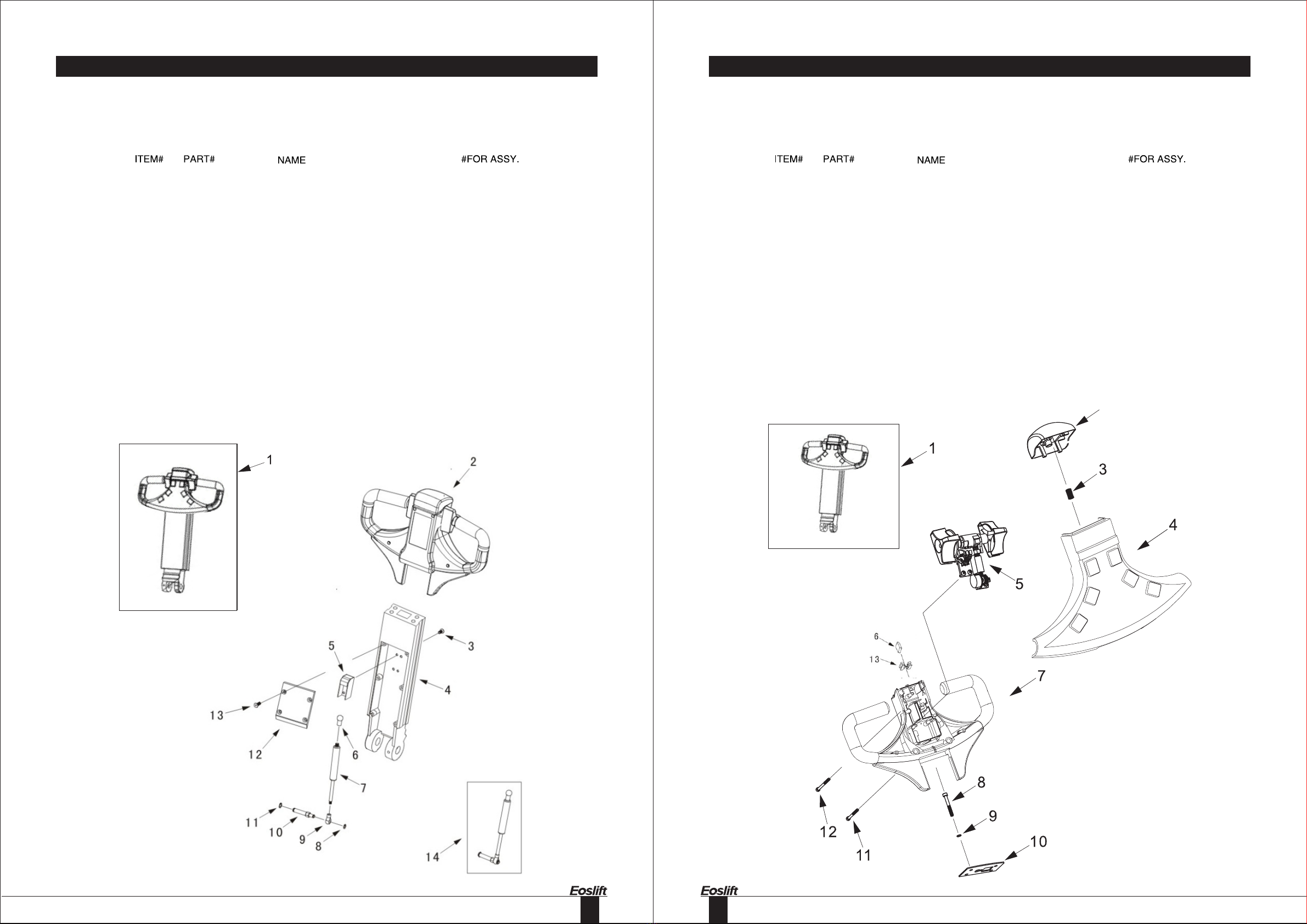
Handle assembly
Switch box assembly
Switch box assembly
Stepped switch assembly
Driving system
Gear box assembly
Driving system
Drive motor
Hydraulic system
Cylinder assembly
Hydraulic power unit
Valve assembly
Oil pump
Frame
Balance wheel assembly
Electric panel assembly
Forked frame
Electric panel assembly
Battery a ssembly
Fig.1
Fig.2
Fig.3
Fig.4
Fig.5
Fig.6
Fig.7
Fig.8
Fig.9
Fig.10
Fig.11
Fig.12
Fig.13
Fig.14
Fig.15
Fig.16
Fig.17
Fig.18
Fig.19
Fig.20
ITEM# DENAME PAGE
1500500001
Lubricated bush
Pin shaft
Pin shaft
Sping pin
Rubber washer
Rubber sack
Rubber sleeve
Steel ball
2000507004
4300501001
Inner covering plate
Handle socket
Electron hanbgrip
32
33
Fig.3 Switch box assembly
5300500002
5300518003
2000519004
5300500001
4300500004
2000507002
5300517002
6000131001
1001437003
1200518001
6000131006
4300531001
9300517001
1
2
3
4
5
6
7
8
9
10
11
12
13
Switch box assembly
Emergency reverser button cover
Spring
Cover assembly
Stepped switch assembly
Emergency reverser button
Handle
Screw
Washer
Supporting plate
Screw
Screw
Seat
1
1
1
1
1
1
1
4
4
1
2
2
1
Fig.2 Handle assembly
1500500001
5300500002
2000442001
4300501004
6000502002
2000525010
4000519004
2000527002
2000520003
2000525006
1000527001
4000517001
2000542001
4000500006
1
2
3
4
5
6
7
8
9
10
11
12
13
14
Handle assembly
Switch box assembly
Screw
Handle tube
Pneumatic spring seat
Joint
Pneumatic spring complete
Snap ring
Joint
Shaft
Snap ring
Covering plate
Screw
Pneumatic spring assembly
1
1
4
1
1
1
1
1
1
1
1
1
4
1
34
35
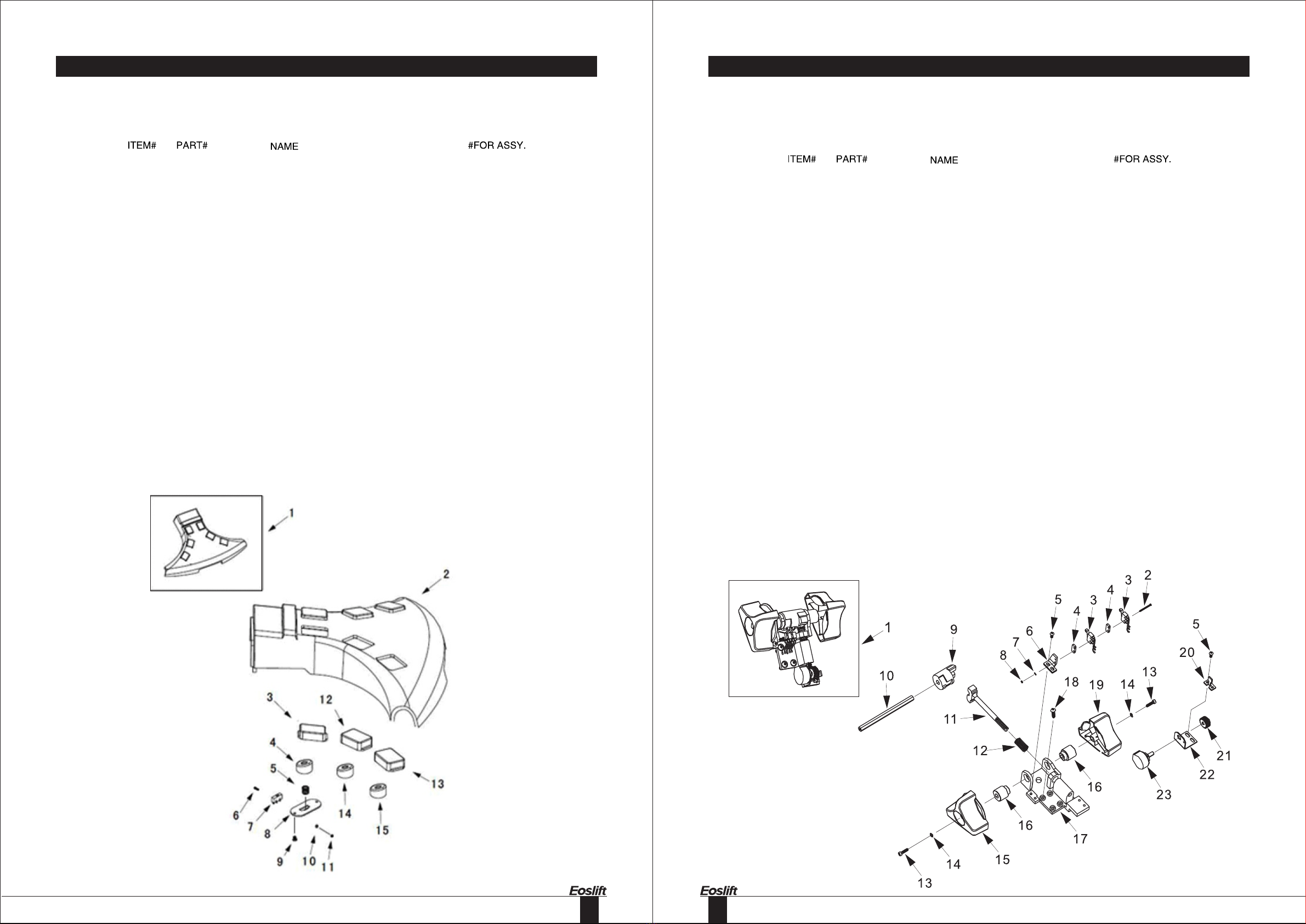
Fig.5 Stepped switch assembly
1
2
3
4
5
6
7
8
9
10
11
12
13
14
15
16
17
18
19
20
21
22
23
4300500004
2000538005
2000507003
2000535001
2001141005
4300518003
1000504001
2000539002
4300501005
4300513001
1002343003
2000519004
4300900002
2001437005
4300540001
4300512001
4300535001
2000541004
4300540002
4300518004
2000521001
4700418001
4700400001
Stepped switch assembly
Screw
Inching switch
Isolate block
Screw
Fastening bracket
Washer
Nut
Cam
Cam shaft
Rack
Spring
Screw
Circlip
Right control knob
Shaft sleeve
Fastening bracket
Screw
Left control knob
Baffle
Gear
Fastening bracket
Potentiometer
1
2
2
2
2
1
2
2
1
1
1
1
2
2
1
2
1
4
1
1
1
1
1
Fig.4 Switch box assembly
1
2
3
4
5
6
7
8
9
10
11
12
13
14
15
4300500007
4300508002
4300508003
4300540003
4300519001
4300541001
2000507002
4300518001
2000441002
1000504001
2000539002
4300508004
4300508005
4300540004
4300540005
Cover assembly
Cover
Button cover
Rubber contact
Spring
Screw
Inching switch
lsolate block
Screw
Washer
Nut
Button cover
Button cover
Rubber contact
Rubber contact
1
1
2
2
6
12
6
6
12
12
12
2
2
2
2

36
37
Fig.7 Gear box assembly
1
2
3
4
5
6
7
8
9
10
11
12
13
14
15
16
17
18
19
20
21
22
23
24
25
Screw
Gear
Nut
Gear
Bearing
Screw
Bolt
Washer
Side cover
O-ring
Bolt
Washer
Gear
Bearing
Washer
Washer
Gear
Flat
Circlip
Screw
Bearing
Seal washer
Spline shaft
Gear box body
Gear box assembly
2000130002
7800321001
2000125001
2000121006
2000120003
2000141001
2000625001
2000603010
2000111002
2000128002
2000130001
2000135001
2000121002
2000120002
2000137001
2000137002
4000201001
4000101001
2001037001
2000731003
2000120001
2000105001
2000121003
2000126001
7800300003
4
1
1
1
2
8
2
2
1
1
1
1
1
1
2
2
1
1
8
8
1
1
1
1
1
Fig.6 Driving system
1
2
3
4
5
6
7
8
9
10
11
12
13
14
15
7800300001
1000131001
2001037001
7800300002
5501221004
7800337001
7800330002
1500318001
0300320001
7800300003
2000325001
4000332001
2000325002
8700406001
9300312002
1
4
4
1
1
1
1
1
1
1
5
1
5
1
1
Electromotor
Screw
Washer
Electromotor
Gear
Washer
Screw
Flange
Axletree
Gear box assembly
Double-head bolt
Drive wheel assembly
Nut
Limittation Switch
Sleeve

38
39
Fig.9 Drive motor
1
2
3
4
5
6
7
8
9
0301415001
0301408001
4300900002
0301411001
2001420001
2001427002
0301412001
0301400002
0301400001
3
1
2
1
1
1
1
1
1
Tie-in
Plastic mantle
Screw
Cover
Bearing
Snapring
Spring
Rotor
Drive motor
Fig.8 Driving system
1
2
3
4
5
6
7
8
9
10
11
12
13
14
15
16
17
Brake assembly
Spline
Snap ring
Sleeve
0-ring
Flat key
Moto r
Screw
Position sleeve
Dus t ring
O-ring
Bearing
Snap ring
Snap ring
Gea r
Semicircle key
Nu t
0301000001
2001021001
2001427001
4301412002
2000628005
2001021001
0301400001
0301431001
2001212003
2001405001
2001228001
2001420001
2001427001
2001227003
2000121005
2001435001
2001425002
1
1
1
1
1
1
1
4
1
1
1
1
1
1
1
1
1

40
41
Fig.11 Cylinder assembly
1
2
3
4
4700613001
2800605002
4700612001
2800605001
1
1
2
1
Pistonrid
Dustring
Supporting tach
Seal washer
Fig.10 Hydraulic system
1
2
3
4
5
Joint
O-ring
Hydraulic power unit
Washer
Joint
8700615004
6000637001
4000600007
1500617001
1500615001
1
2
1
1
1

42
43
Fig.13Valve assembly
Fig.12 Hydraulic power unit
1
2
3
4
5
6
7
8
9
10
11
12
13
1001400001
2000612004
4000600006
1000628001
1000600007
2000631003
2000631001
1000626001
1000609001
1000741001
1000635002
1000605005
1000605006
1
1
1
1
1
2
2
1
4
4
1
1
1
Hydraulic motor
Connecting bearing sleeve
Valve assembly
O-ring
Oil pump
Screw
Screw
Oil tank
Washer
Screw
Joint
Oil plug
Cover

44
45
Fig.14 Oil pump
1
2
3
4
5
6
7
8
9
10
11
12
13
14
15
2000628001
2000605006
2000628002
4000611001
2000628016
2000628017
2000605002
2000612002
1000621005
1000621006
2000633001
1000603006
2000611006
2000628019
4000625002
1
1
1
1
2
2
2
2
1
1
4
1
1
1
1
O-ring
Seal washer
O-ring
Oil out cover
O-ring
O-ring
O-ring protection washer
Oil discharge block
Drive gear
Driven gear
Pin
Pump body
Oil feed cover
O-ring
Oil suction pipe
Fig.13 Valve assembly
1
2
3
4
5
6
7
8
9
10
11
12
13
14
15
16
17
18
19
20
21
22
23
24
25
26
27
28
29
30
31
32
33
2
2
1
2
1
1
1
1
1
2
1
1
1
1
1
1
1
1
1
1
1
1
1
1
1
1
1
1
1
1
1
1
1
1
2000630001
2000637001
2000625003
2000628014
2000619004
2000614008
4000603010
2000619001
2000613003
2000628007
2000612006
2000628015
2000610001
2000628001
2000603018
1000603003
2000628018
2000637005
2000634002
1000603012
2000628009
2000619003
2000613001
2000504001
2000603004
2000628010
2000634001
1000604001
1000603013
1000619001
1000303014
2000637002
1000603016
Bolt
Washer
Bolt
O-ring
Spring
Core of slide valve
Valve body
Spring
Core of slide valve
O-ring
Slide valve sleeve
O-ring
Washer
O-ring
Electromagnetic coil
Plug
O-ring
Washer
Filter net
Valve holder
O-ring
Spring
Spring socket
Steel ball
Valve holder
O-ring
O-ring protection washer
Steel ball
Spring socket
Spring
Pressure adjusting bolt
Washer
Nut

46
47
Fig.16 Banlance wheel assembly
1
2
3
4
5
6
7
8
9
10
11
12
13
14
15
16
17
18
4300327001
7300712002
7300320001
7300218001
1001031003
7301218001
1000339001
2000737003
2000305001
2300312001
1000320002
4000312002
2700332001
7300330001
7300300001
4300304001
4300720002
7300305001
1
1
1
1
6
1
1
1
2
2
2
1
1
1
1
1
1
1
Mat
Mat
Bearing
Wheel seat
Screw
Wheel bracket
Nut
Circlip
Dust ring
Bush
Bearing
Wheel sleeve
Balance wheel
Screw
Balance wheel assembly
Nut
Bearing
Pressurize circle
Fig.15 Frame
1
2
3
4
1500724001
1500724002
7300300001
1500400001
1
1
1
1
Frame
Bracket
Balance wheel assembly
Electric panel assembly
Table of contents
Other Eoslift Truck manuals


Popular Truck manuals by other brands


EP Equipment
EP Equipment CQD15S-E Operation manual

Sealey
Sealey Premier CST990HD quick start guide

Eagle
Eagle TT Series Parts and service manual

STEWART-AMOS
STEWART-AMOS Starfire S-6t 2012 Operation and maintenance manual

Komatsu
Komatsu 210M Operation & maintenance manual

Dawson
Dawson Truck Mate Operator's manual