AluTeam BR 248-2 User manual

Always read through these instructions, completely
and carefully, before you start the assembly work.
MA2482.ENG
Assembly Instructions BR 248-2
Box Body Kits
AluTeam Fahrzeugtechnik GmbH
Brockhagener Straße 88, D - 33649 Bielefeld
Tel. + 49 (0)521 - 41 73 11 - 0, Fax + 49 (0)521 - 41 73 11 - 90

Series 248-2 Assembly Instructions Dated 11/2021 Previous instructions become invalid. 2 / 12
Table of Contents
1. Safety Instructions and Warnings 2
1.1 Checking the kit contents 2
1.2 Warnings 2
1.3 Safety instructions 3
1.4 Copyright 4
2. Preparatory work / Personnel requirements 4
2.1 Personnel requirements 4
2.2 Tools and equipment required 4
2.3 Tightening torques of the bolts and screws 4
2.4 Preparations 5
3. Assembling the kit on the floor 5
3.1 Assembling the walls 5
3.2 Installing the frame crossmember 6
3.3 Attaching the roof 6
3.4 Wiring the kit and fastening the roof 6
3.5 Assembling the frame, doors, etc. 8
3.6 Sealing 8
3.7 Positioning on the underbody or chassis 8
4. Finishing Work 9
5. Maintenance, Service 11
5.1 Maintenance 11
5.2 Service 11
6. Disposal of Old Box Bodies and Components 11
7. Kit Contents 12
These instructions explain how to assemble the 248-2 kit with alumini-
um frame. To create a fault-free body, always follow the work instruc-
tions described, especially the following warnings, otherwise the war-
ranty is voided.
If you ordered a steel frame or another custom design, it is possible
that individual work steps are not explained here. Note: coloured rep-
resentations are for illustration purposes only. Get in touch with us
immediately in case of uncertainties.
1.1 Checking the kit contents
Check the delivery against the enclosed packing list for
completeness. Notify the delivering carrier immediately of any trans-
port damage. Please understand that we must reserve the right to make
changes to the design, features and technology delivered. The general
kit contents are listed on page 12.
1.2 Warnings
AluTeam generally does not know the precise intended purpose of the
kit. As the body builder, you must match the order and use of the
kit to the requirements of your customer and the body
guidelines of the vehicle manufacturers. This also applies to materi-
als used and surface finishes. Damage due to transport goods such as
aggressive chemicals are not a reason for complaint.
•Store the kit in a dry and clean place (not outdoors).
1. Safety Instructions and Warnings
Always read through these instructions, completely and carefully, before assembling the kit!

Series 248-2 Assembly Instructions Dated 11/2021 Previous instructions become invalid. 3 / 12
•To ensure water cannot penetrate the assembled box body, the
sealing cords in the profiles must not show any signs of damage.
•Connect the components directly using the screws supplied.
The assembly contact surfaces must be free from dirt.
•Use the original screws and bolts, and use them only once (even for
repairs). Third party / used screws and bolts endanger operational
safety. Screws must not tilt. Never position the screws or bolts at an
angle and keep to the specified torques (2.3). A torque lower than
specified weakens the strength and tightness of the body, a signifi-
cant exceedance can cause damage to components!
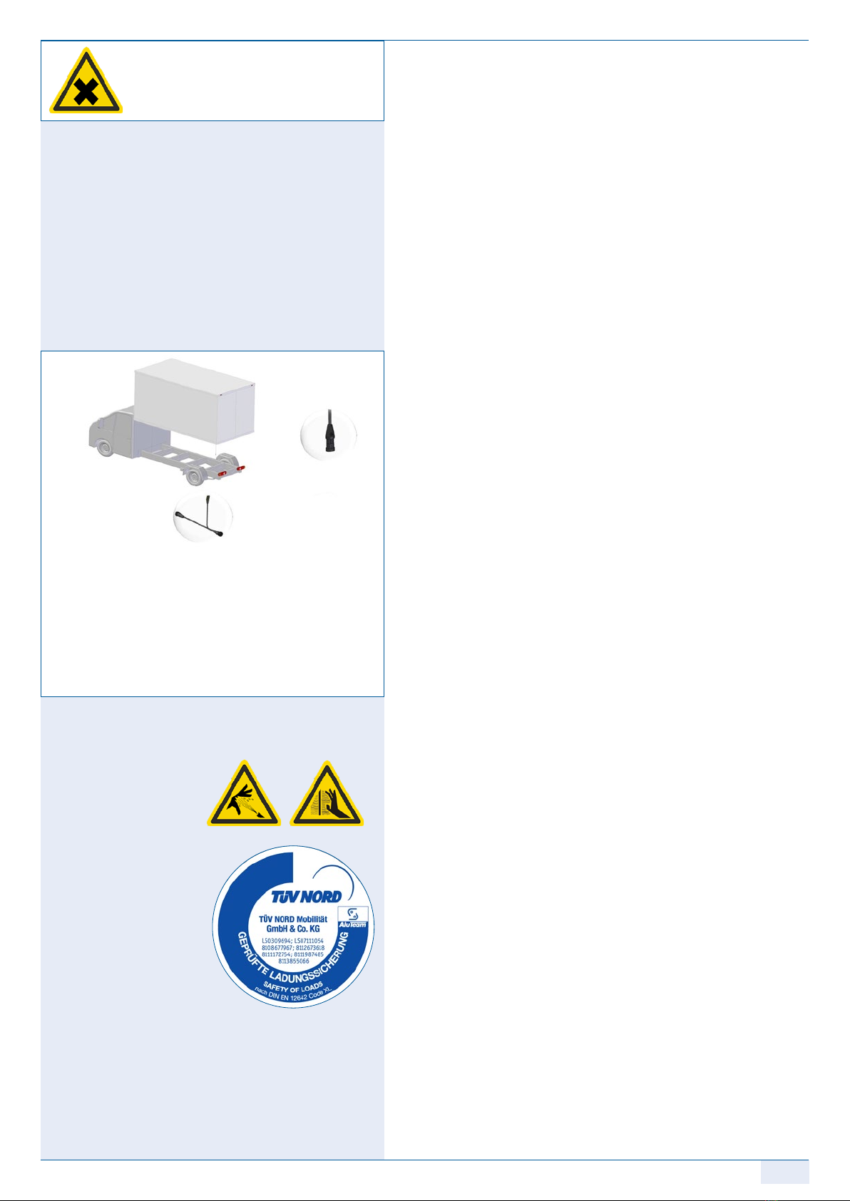
•The body is not designed for docking operations! Set out the un-
derbody so that forces acting through rear bumper guards are trans-
ferred into the auxiliary frames or the chassis.
•The fastenings between the longitudinal chassis beams and chassis
frame must be made as described in the body guidelines of the
respective chassis manufacturer. The two front fastenings at least
must be spring-mounted. Otherwise, forces that occur, e.g. in case of
cornering, load changes or non-uniform loading, are transferred onto
the body and can cause cracks in the body structure.
1.3 Safety instructions
Pay attention to your own safety and to that of your employees.
Working with kits involves hazards. Therefore, caution is always
necessary, in particular, you should definitely:
... Wear safety gloves. Wear safety footwear, as heavy parts can fall.
Wear hearing protectionas well as safety goggles when working
with air screwdrivers, grills, grinding equipment, etc. Wear a helmet
when working with or near a crane.
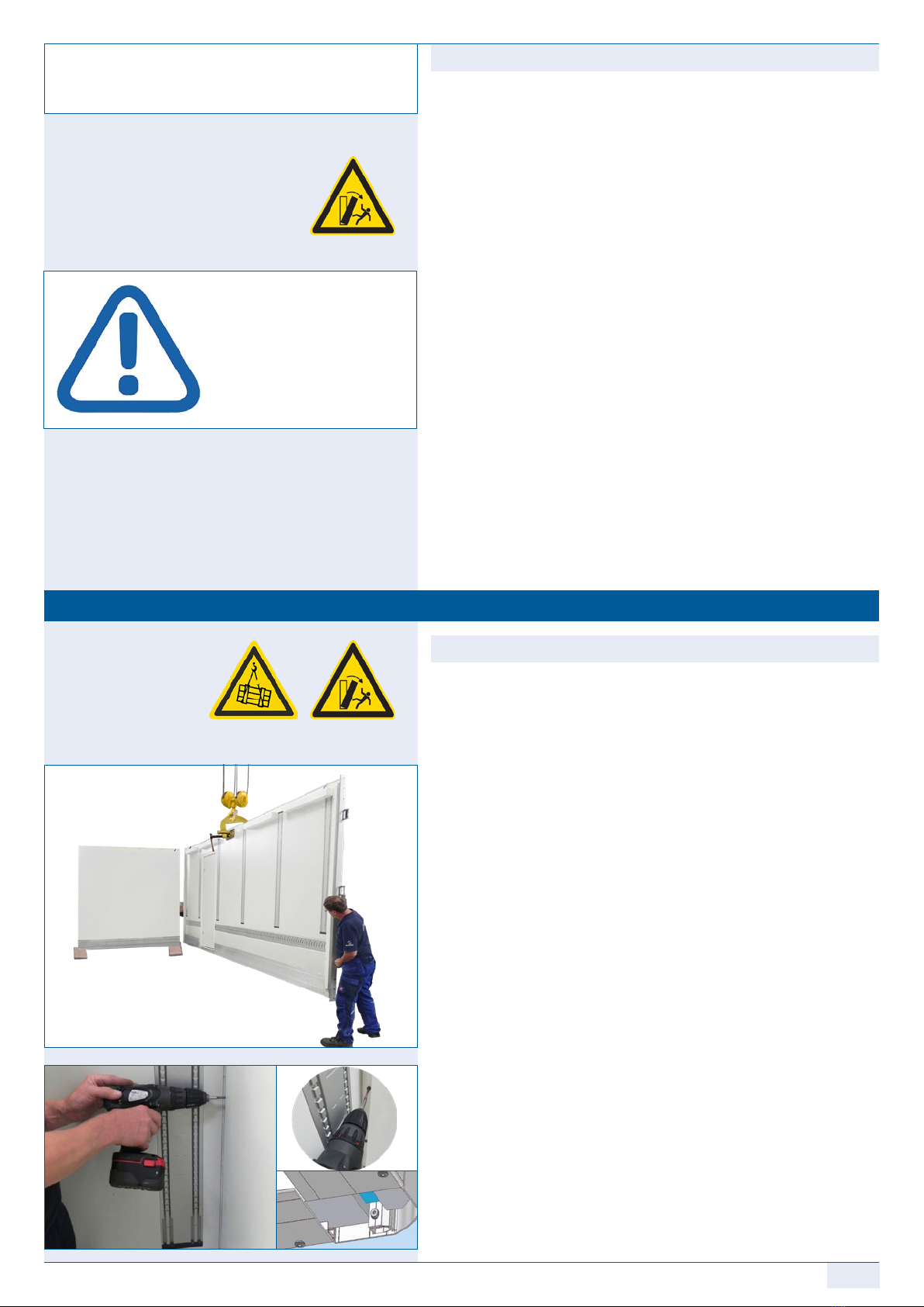
... when unloading /transporting the kit in the transport rack using a
crane, use a suitable lifting beam. If using a forklift truck, push the
transport rack completely onto the fork arms.
... Place transport racks on level surfaces only and secure them against
tilting and toppling, secure any assembly dollies against rolling
away.
... Always lift assemblies vertically, not at an angle! Never step under
raised loads! The suspension point/anchorage in the crane must al-
ways be above the assembly’s centre of gravity!
... remove all packing straps in the specified order during assembly,
always remove the white packing straps first. The individual compo-
nents and assemblies are held by a red packing strap. Secure the part
to be removed against toppling before cutting the packing strap.
... lift the roof with a lifting beam or vacuum lifter only! The roof
mounting strips (airline rails) are used as an assembly aid only. They
must not be used to lift assembled box bodies. Risk of pulling out!
... comply with all relevant legal requirements in your country, such
as laws, regulations, etc. regarding road traffic and goods transport,
as well as all relevant occupational health and safety regulations.
This is the responsibility of the body builder.
... ensure adequate ventilation when cleaning and sealing and follow
the use, safety and disposal instructions of the adhesive / sealant
manufacturer. Request the safety sheet and the instructions for
use from the manufacturer as printed on the cartridge or contact
+49 (0)521 4173 -1110.
1
2
suspended
loads on the
crane
Risk due to
high-pressure
cleaners
falling
objects
Risk of
scalding
hazardous
materials
toppling parts
or assemblies

Series 248-2 Assembly Instructions Dated 11/2021 Previous instructions become invalid. 4 / 12
©2.1 Personnel requirements
1-2 fitters with training as a vehicle or vehicle body builder or equiva-
lent training are required.
2.2 Tools and equipment required
Before starting the assembly, make sure the following equipment
is to hand:
o Measuring tape
o Precision air or cordless screwdriver with torque setting up
to 12 Nm (e.gB. Fein Accutec or comparable)
o Power screwdriver bit Tx 30 (DIN 3126 / ISO 1173), extra hard type,
¼” drive, min. 70 mm length (AluTeam Article No. MH170107)
An extension for screwdriver pits may be useful
o Ratchet and sockets for hexagon socket size 6 and 8
o Torque wrench up to 200 Nm
o Carrying straps with 4 double-stud fittings
(e.g. LoadLok 5018 or allsafe JUNGFALK 7105/75018)
o Assembly dolly or Euro pallets or suitable support trestles
o Pneumatic or manual dispenser gun for 310 ml sealant cartridges
o Rivet gun for rivet diameter 5 mm
o Crane with at least 1 tonne working load limit
and vacuum lifting beam or lifting gear
o 4 wooden panels approx. 300 x 300 mm (20 mm stark) or similar
o Hammer (500 g), Punch d = 3 mm and d = 4 mm
o 2 standing ladders or scaffold unit
o HSS drill bit Ø 5.0 mm (shorter than the wall thickness!)
o Painter's putty knife
2.3 Tightening torques for screws and bolts
You only join the components together directly. After setting it, the
named power screwdriver type has a uniform, tight tightening torque.
The torques apply to a dry thread. The settings for the screws and bolts
must be checked using appropriate measuring equipment. Set the fol-
lowing torque:
oAssembly screw M 6 x 21 10 Nm ± 1 Nm
o Pan head screw with flange M 6 x 26 5 Nm ± 1 Nm
o Countersunk screw M 10 x 30 60 Nm ± 5 Nm
oFrame screw M 12 x 45 125 Nm ± 5 Nm
2. Preparatory work / personnel requirements
AluTeam kits can be assembled in any well-
equipped workshop. Carry out the following
preparations beforehand.
1.4 Copyright
AluTeam holds the copyright to these instructions. They are intended
for the assembly company and its personnel and may not, neither as a
whole nor in part, be:
• reproduced
• distributed or
• otherwise disclosed.
Infringements can result in civil and criminal charges!

Series 248-2 Assembly Instructions Dated 11/2021 Previous instructions become invalid. 5 / 12
2.4 Preparations
•Check the delivery (1.1) and check that the bottom rail of the
walls as well as the floor section are undamaged. Damage can make
the assembly difficult or even impossible!
•Note and follow the safety instructions and warnings (1.2 & 1.3).
In particular, secure the overall kit against toppling, as well as the
individual assemblies. These are stored on the pallet in the order
they are required to assemble the body. Therefore, do not cut the red
straps securing one component each until the assembly is removed.
•Provide sufficient free space (at lest 3 m) on both sides, as well as
in front of and behind the vehicle or assembly area and the required
Tools and Equipment (2.2) .
•The ambient temperature for components as well as adhesives and
sealants must be at least 15°C.
•The following describes off-vehicle preassembly. To this end, carry
out the assembly on a level floor. To protect the painted components
and to make alignment easier, place e.g. wooden panels 300 x 300
mm (at least 20 mm thick) or similar on the floor under the corners
of the front wall / side wall and side wall / rear frame.
3.1 Assembling the walls
•Use a crane and lifting gear or a vacuum lifting beam to remove the
front wall (bulkhead) from the transport unit and carefully place it
on the plywood boards.
Danger: Toppling assemblies are at risk to life and limb.
The wall therefore remains secured, e.g. in the crane.
•Remove the first side wall in the same way and push it onto the
front wall at right-angles.
Attention: The corner pillars must not be closed off at the bottom,
as it may be necessary to lay cables through them later.
•One fitter secures the components on the outside. The 2nd employee
MD100224 (torque 10 Nm ±1) up to a approx. ¾ of the box height,
starting at the bottom, until the sections are pressed together. If
necessary, use punches as an assembly aid.
•Remove the second wall (as described above) from the transport
rack. Position the wall and align it at right-angles with the front
wall; the wall remains hanging from the crane initially.
•Now screw in 3 - 4 screws MD100224 again, starting from the bottom
up to approx. ¾ of the box height, until the sections are pressed
together and the required torque (10 Nm ± 1) is reached.
3. Assembling the kit on the floor
AluTeam kits can be assembled in any well-
equipped workshop. Carry out the following
preparations beforehand.
Attention: If you use adhesives or
sealants other than those
supplied by AluTeam, you
are responsible for the
seals and bonding carried
out with these alternative
products. No warranty is
provided for them.

Series 248-2 Assembly Instructions Dated 11/2021 Previous instructions become invalid. 6 / 12
3.2 Installing the frame crossmembers
•Now position the bottom frame crossmember supplied between the
frame pillars.
•Fix the crossmember from the outside of the pillars with 4 screws
M 12 x 45 mm each. Do not tighten the screws yet!
•You have now stably connected all the walls to each other. Check
and if necessary, correct the angularity and diagonal dimensions
of the parts assembled until now.
3.3 Attaching the roof
•If a kit includes doors, before attaching the roof, undo the lashing
straps of the doors. However, the doors must continue to be secured
against turning.
•If a kit includes a top tailgate, use assembly screws (included in the
material for the top gate) to fix it onto the roof flange using the
holes provided in the hinge.
•Use a crane and lifting gear or vacuum lifting beam to remove the
roof from the transport unit. Position the roof horizontally and hook
the single-stud fittings into the roof assembly rails (if you are work-
ing without a vacuum lifting beam). The fittings must be tight! 4 or
more fittings are required, depending on the kit length.
•Push the top frame gusset plates, with the pointed tip facing down-
wards, sideways into the frame crossmember. If applicable, insert
the side lights into the crossmember.
•Screw the gusset plates with 2 screws MD 100227 and plain washers
10.5 mm each by hand so that they are slightly tightened.
•Lift the roof with the single-stud fittings or the vacuum lifting
beam. Centre the roof, starting from the front, on the top rail of
the front wall (bulkhead). The roof caps grip over the corner pillars.
Align the roof with the wall sections.
Danger: Never step under raised loads! Wear a helmet. Lift the
horizontal roof at the assembly’s centre of gravity,
never lift it with an inclined angle (see 1.3)!
3.4 Wiring the kit and fastening the roof
•Lower the roof slowly. If necessary, use a painter’s putty knife as
an assembly aid. Centre the downward pointing frame gusset plates
in the pillars. Fix them on each side with three vertically positioned
hexagon head cap screws MD100227 and plain washer 10.5 mm -
finger-tight!
Attention: The screws must not tilt, the cables and connectors
must not be crushed!
•Install the cable connections of the 248-2 kits as follows:
• To wire the side lights, fit together the
1. plug-in connection on the right and push
2. the cables into the right-hand frame pillar.
Floor support
Adapter
MA 350147
Adapter
MA 350148
MA 350151
MA 350151
3. Brake
light
MA 350143
MA 350081
MA 350149
Molex pin
Molex socket
1
Driving direction
2

Series 248-2 Assembly Instructions Dated 11/2021 Previous instructions become invalid. 7 / 12
•Now continue to connect the various lights:
• To wire the LED strips with motion detectors (infrared sen-
sor), fit together only 1. the connectors and push 2. the plug-in
connection downwards into the left-hand frame pillar.
• To wire the LED strips without motion detectors fit together
only 1. the connectors and push 2. the plug-in connection
downwards into the left-hand frame pillar.
Note: The figure shows wiring with LED strips on the right
and/or on the left-hand side.
•Fix the gusset plate in the corner pillars with 3 M 10 x 30 countersunk
screws MD100268 positioned on each side (tightening torque
60 Nm ± 5 Nm).
•Screw the roof from the top using 3 - 4 screws on each side
MD100318 together with ring seals MD110044 uniformly distribut-
ed, each from the front to the back. Set the screwdriver tightening
torque to 5 Nm ± 1 Nm.
Attention: To maintain the sealing function, the sealing washer
must not be pressed out from under the screw head by
more than approx. 0.5 - 1 mm!
•Measure the diagonals of the frame and correct them if necessary,
until they match each other.
•Screwing the remaining screws MD100224, M 6 x 21 mm Tx 30 to
a tightening torque of 10 Nm ± 1 Nm vertically into the side
walls-front wall connection, until the sections are pressed together.
•Fill the remaining cavity between the front wall and side wall panel
with the piece of cut foam supplied.
•Then close off the vertical front inside body corners with the corner
covers using the rivets MD150023.
•Screw the remaining screws MD100318 with the ring seal MD110044
into the connection of the roof and walls. Again, pay attention to
deformation of the sealing washer (see above).
•Tighten the screws MD100268 of the frame gusset plates at the top
as well as the screws M 12 x 45 mm, MD100307 of the frame cross
member to the required torque of 125 Nm ± 5 Nm.
Attention: The rear surface of the two crossmembers must form a
flush plane with the rear surface of the pillars.
•Now seal the component crossovers of the frame.
•Remove the single-stud fittings from the roof assembly rails.
•If necessary, screw the inside right handle onto the frame pillar.
•Close off the side screw holes in the rear pillars using the plugs supplied.
0.5-1
correct wrong wrong
MA 350081
MA 350081
MA 350120
MA 350081
MA 350120
Power IN cable
Power IN cable
Roof edge
MA 350114...19,
MA 350141
MA 350114...19,
MA 350141
LED strip, rightLED strip, left
12
Roof edge
MA 350114...19, MA 350141
MA 350127
MA 350081
Power IN cable
MA 350081
MA 350126
1
2
Driving direction
Driving direction

Series 248-2 Assembly Instructions Dated 11/2021 Previous instructions become invalid. 8 / 12
3.5 Assembling the frame, doors, etc.
•If the kits have a top gate, latch the gas springs of the gate onto the
ball heads. If the frame pillar does not have an integrated seal, the
gate must be secured against lateral movement during operation us-
ing two brackets as shown in the sketch.
•If a kit includes rear doors, they must be closed to check the fit. If
necessary, adjust the rotary bar locks by adjusting the position of
the hitches. Always re-check the screws for tight fit.
•In the case of kits with supplied roller shutter, the roller shutter
must be installed as described in the instructions supplied, “Installa-
tion of DP 25HR-d 2007”. Rivet the guide rails onto the preassembled
horizontal top-hat sections.
3.6 Sealing
•Use the bond-activating cleaner of the kit to clean the sealing
surfaces and after approx. 10 sec. flash-off time, treat with Sika
Activator 205.
•After approx. 10 min. flash-off, seal with the sealing compound:
Front right and left roof corner, all round from above and the rivet
head.
The connection of the walls to the roof and the corner cover.
The connections of the top frame crossmember to the pillars.
•The seals should only be pressed in and smoothened with
smoothing agent or water —without soap additives.
•If necessary, the joint between the side door and the floor must also
be sealed.
3.7 Positioning on the underbody or chassis
•Fasten the box body onto the substructure as shown in the sketch
on the left.
Attention: Failing to follow the bolting instruction will cause
the warranty to be voided.
•The design of the substructure is the responsibility of the vehicle
builder, and must follow the body and conversion guidelines of the
respective chassis manufacturer. In particular, take into considera-
tion the positioning, the intended use of the body as well as the type
of connection, flexible or stiff under shear.
Forces acting on the rear bumper guard must be reliably and safely
transferred into the auxiliary frame or chassis. The frame and body
are not designed to absorb forces caused by docking operations
(see 1.2)!
•Position the underbody or the chassis, aligned horizontally and
torsion-free, on a level surface.
F
Substructure bolting
instruction
max. 625 mm,
M 10 - 8.8
max. 450 mm,
Ø 6.5 mma
Distance from the wall 25 mm
1
1
2
2
3
3

Series 248-2 Assembly Instructions Dated 11/2021 Previous instructions become invalid. 9 / 12
•In case of side doors, the drain holes for the water must remain
clear even after installation on the external subframe!
•Use the crane and a lighting gear to position the finished box body
onto the subframe or the chassis (Fig. 3.7.1). Never lift the
assembled box body by the roof eyebolts. Risk of pulling out!
•In case of bodies with multi-leaf side doors, if necessary, stiffen the
subframe in the area of the side doors and approx. 1 m to the right
and left of it. If necessary, the stiffening must be extended over the
fulllength of the body. The body builder is responsible for the design
and its execution.
•In case of bodies with coupé doors, you must stiffen the subframe
at the coupé doors as well as approx. 1 m to the right of them, espe-
cially in the area of the step; e.g. by reinforcing with gusset plates.
The body builder is responsible for this.
•When installing floorboards/panels, always take into consideration
their swelling behaviour. Ask your board/panel supplier. Basically,
the joint between the floor and the body must be sealed. The body
builder is solely responsible for this.
the
•After mounting the box body on the substrukture, latch the cover
into the bottom rail section (drawing on the left). Insert the cover
into the clean (cleaned) bottom groove and knock or press it in from
one end, starting from the top. Depending on the kit length, this is a
task for 2 employees.
Attention: If box bodies are unpainted, do not attach the cover
until after painting, to prevent corrosion damage.
•After mounting the covers, use bond-activating cleaner to clean the
remaining vertical gap between the bottom rail or rather the cover
and the respective front and rear pillar and seal it with 1C sealant.
•The assembled box body can be handled, but not loaded. Note that
the final strength of the sealant is not reached until after 24 hours at
20 °C. The operating temperature should not be below 15 ° Celsius.
•In case of subsequently mounted parts or changes to AluTeam com-
ponents, pay attention to corrosion protection and above all,
prevent contact corrosion caused by different materials!
Otherwise the guarantee and warranty for the painting and coating
will be voided.
4. Finishing Work
F
Substructure bolting
instruction
max. 625 mm,
M 10 - 8.8
max. 450 mm,
Ø 6.5 mma
Distance from the wall 25 mm
Keep the water drain holes clear

Series 248-2 Assembly Instructions Dated 11/2021 Previous instructions become invalid. 10 / 12
•Unless ordered otherwise, the kit is finish coated. If necessary, paint
coilcoating and powder-coated parts with conventional wet paints.
For secure, reliable adhesion, consult the paint supplier, especially
regarding the primer. Untreated and galvanised sections must be
treated with a suitable primer before painting. Grind the finish-coat-
ed parts supplied with the abrasive pad and remove dust and grease
to prepare them for painting. The temperature in the paint booth
must not exceed 60°C.
•Do not clean the body with a steam jet cleaner for at least 6 weeks.
To prevent paint damage, maintain a minimum nozzle distance of
approx. 300 mm. The water temperature must not exceed 60 °C, The
maximum allowable water temperature of the cleaner is 60°C, the
maximum working pressure is 100 bar, and the pH-value is 4 - 10.
Then rinse immediately with plenty of clean water. Remove flash rust
on stainless steel parts (including the frame) using common house-
hold stainless-steel cleaners. After cleaning, treat all seals with rub-
bing care product.
•After mounting the box body on the underbody, depending on the
supplied features, pull the connection cable for the side lights
out of the frame pillar and use the adapter cable supplied to connect
it to the connection cable of the respective vehicle manufacturer.
•Connecting the interior lighting to the chassis s the sole respon-
sibility of the body builder. Always follow the body guidelines of the
chassis manufacturer.
•After assembling the box body, please only check the roof corners,
doors and the lighting for leaks.
•To perform a water test on bodies, based on EN 283, use a water jet
from a ½” nozzle (Ø 12.5 mm inside) to test the external seal welds,
at a pressure of roughly 1 bar. The nozzle must be held at a distance
of at least 1.5 m from the body to be tested. After testing, there must
be no penetrated water in the body.
•Body strength stickers are only valid in conjunction with a body
strength certificate of an independent test organisation issued
through AluTeam.
Plug-in connection
in the right-hand
frame pillar
Supplied connection cable
Mercedes: Atego , Antos, Actros - MA350155 & MA350083
MAN TGM, TGL, TGE, as well as VW Crafter and Scania: MA350158
DAF: MA350157 & MA350156
Iveco Eurocargo: MA350190 / Iveco Daily: MA350159
MB Sprinter, Opel Movano Citroen Jumper Peugeot Boxer: MA350158
Mitsubishi Fuso Canter, Fiat Ducato, , Renault Master: MA350158
Ford Transit: MA350168
Attention: Paints, solvents
and dust are harmful to health.
Protect yourself!

Series 248-2 Assembly Instructions Dated 11/2021 Previous instructions become invalid. 11 / 12
5.1 Maintenance
Visually inspect body screws with sealing washer regularly. If neces-
sary, replace seals (e.g. which swell out)and screws. At the same time,
check the specified torque.
•Locks and lock cylinders are maintenance parts. Lubricate them to
keep them in working order if necessary. Frozen locks due to lack of
maintenance are not a reason for complaint.
•To clean the body with the steam jet cleaner, follow the correspond-
ing instructions in 4. Finishing work.
•Check all seals regularly and always treat with a rubber care product
after cleaning.
5.2 Service
If you have any questions regarding the assembly, please contact our
customer service:
If you require spare parts, please either contact your local sales repre-
sentative or call us on: +49 (0)521 - 41 73 11 - 10.
•You can remove the metallic outer layers from the foam core and,
like the aluminium sections, hand them over to the scrap trade for
recycling. The same applies to the steel and / or stainless steel com-
ponents of the frames.
•A PUR foam core can be incinerated in thermal waste treatment
plants without polluting the environment. Plywood, like particle-
boards, can be burned in wood-fired furnaces with at least 50 kW
nominal heat output. They are subject to stricter carbon monoxide
limits than solid wood. These values are mostly only achieved by
automatically loaded plants. Odour nuisance due to the ammonium
additives in the binders must be avoided.
•GRP must be processed by a recycling/recovery company, and is used
as a substitute fuel. For energy recovery in a cement works, the EWC
code is 070213 (waste plastic).
•For information on disposing of the foam in the area of the floor,
contact the trade association for extruded polystyrene foam (in Ger-
many: Fachvereinigung Polystyrol-Extruderschaumstoff (FPX), Od-
enwaldring 68, 64380 Rossdorf (https://xps-spezialdaemmstoff.de/
wpcontent/uploads/XPS-mit-halogenfreien-Treibmitteln-1.pdf).
•Hardened adhesives and sealants are disposed of as residual waste
(black bin). Residual quantities of solvents, as hazardous waste,
must be handed into the respective disposal company or collec-
tion point. The technical data sheets can be requested from the
individual manufacturers.
5. Maintenance, Service
6. Disposal of Old Box Bodies and Components

Series 248-2 Assembly Instructions Dated 11/2021 Previous instructions become invalid. 12 / 12
Please understand that we must reserve the right to make changes to
the design, features and technology delivered.
A BR248-2 kit includes:
o Front wall assembly
o 2 x side wall assemblies (rh/lh) with mounted rear pillars
and, depending on features, with attached doors
o Roof assembly with integrated frame crossmember incl. frame
gusset plate as well as preassembled roof corners
o Optional rear steel frame, e.g. in kits with roller shutters
o In case of liftgate kits: Top tailgate with pneumatic spring and
Mounting screws MD100058
o Bottom frame crossmember, depending on the features
o Assembly screw M 6 x 21 Tx30 self-locking,
AluTeam Article No.: MD100224
o Pan head screws with flange for connecting the wall elements
to the roof from above, M 6 x 26, AluTeam No.: MD100318
as well as suitable ring seals
o Ring seal MD 110044 for the assembly screw MD 100318
o Screws M 12 x 45, MD100307 for connecting the aluminium
pillars to the bottom frame crossmember
o 2 x corner covers for the vertical front body inside corners
o Depending on features, 2 x galvanised frame gusset plates, bolted
type, as corner connector for the integrated frame
o Ifnecessary,2piecesofcutfoamforthecavitybetweenthefrontwall
and the side wall
o Plugs for bolting holes in the frame pillars
o Avinox blind rivet Ø 4.8 x 11.3 VA Article No.: MD150023
o Countersunk screw M 10 x 30 galv., MD 100268 Connection of
aluminium pillars to top frame crossmember
o If necessary, cover for the bottom rails, side and front
o If necessary, handle
o Depending on the features, rear side lights (see circuit diagram)
o If necessary, side marking lights with a connection kit
o If applicable, a connection cable for truck chassis as stated in the
purchase order (see circuit diagram)
o Sealants, white and grey (stainless steel frame)
o Pretreatment agent, cleaner, activator
o Paper towels
o Sticker with body number
o Optional sticker “Tested load security”
Attention: The sticker is only valid with a certificate issued by AluTeam
o Assembly Instructions
7. Kit Contents
Table of contents
Other AluTeam Truck manuals