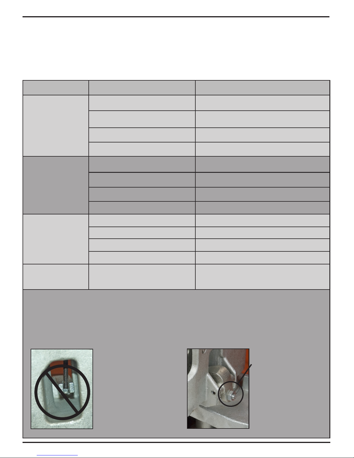
Kleton MN059 User manual

Instruction Manual
Galvanized Hydraulic Hand Pallet Truck
(MN059 & MN648)
9008-08/29/07
9258-01/15/16

WARNING!
• Readandunderstandtheentireoperator’smanualbeforeusingthepallettruck.
• Don’tloadpallettruckbeyondratedcapacityof5,500lbs.
• Secureloadbeforetransporting.
• Keeptheloadcenteredonthepallet.
• Don’toperateloadedpallettruckonrampsorinclines.
• Alwayswearappropriatesafetyshoes.
• Neverleavealoadedpallettruckunattendedintheraisedposition;
alwayslowerloadtotheoor.
PALLET TRUCK ASSEMBLY
Note:Individual trucks are assembled and ready to use. Pallet trucks purchased in
crate quantities (6 units to a crate) require some assembly.
Toolsneededforassembly:hammer, flat screwdriver, 14mm wrench
*** IMPORTANT - SAFETY ***
Verify that spring safety pin is in place.
The pin should be well rested in the
holes situated on each side of the pump
housing. If the safety pin is not rested
properly in one of the holes, put pres-
sure on the spring using a “C" clamp
pushing down on the pump stem. Once
pressure is relieved on the pin, reinsert
properly and remove clamp slowly,
To attach handle assembly to the frame:
If handle pin’s center hole is
facing away from you, insert pin
from other side.
*** IMPORTANT - FACT ***
The up/down lever’s chain
passes through this center hole.
If left this way, the chain will
have an “S" form and be under
too much tension, making the
up/down lever difficult to use
accurately.
1.
Insert handle pin without the
handle and verify that the center
hole is facing you.
3. 4.
Insert handle pin into cor-
responding holes and using a
hammer, drive in one spring pin
on one side only.
2.

*** IMPORTANT - CHAIN****
Before this step, make sure to
feed the chain on the outside
of the piston stem roller (see
yellow arrow). If left in its proper
position, it will not be possible to
insert the handle pin and chain,
breakage may occur.
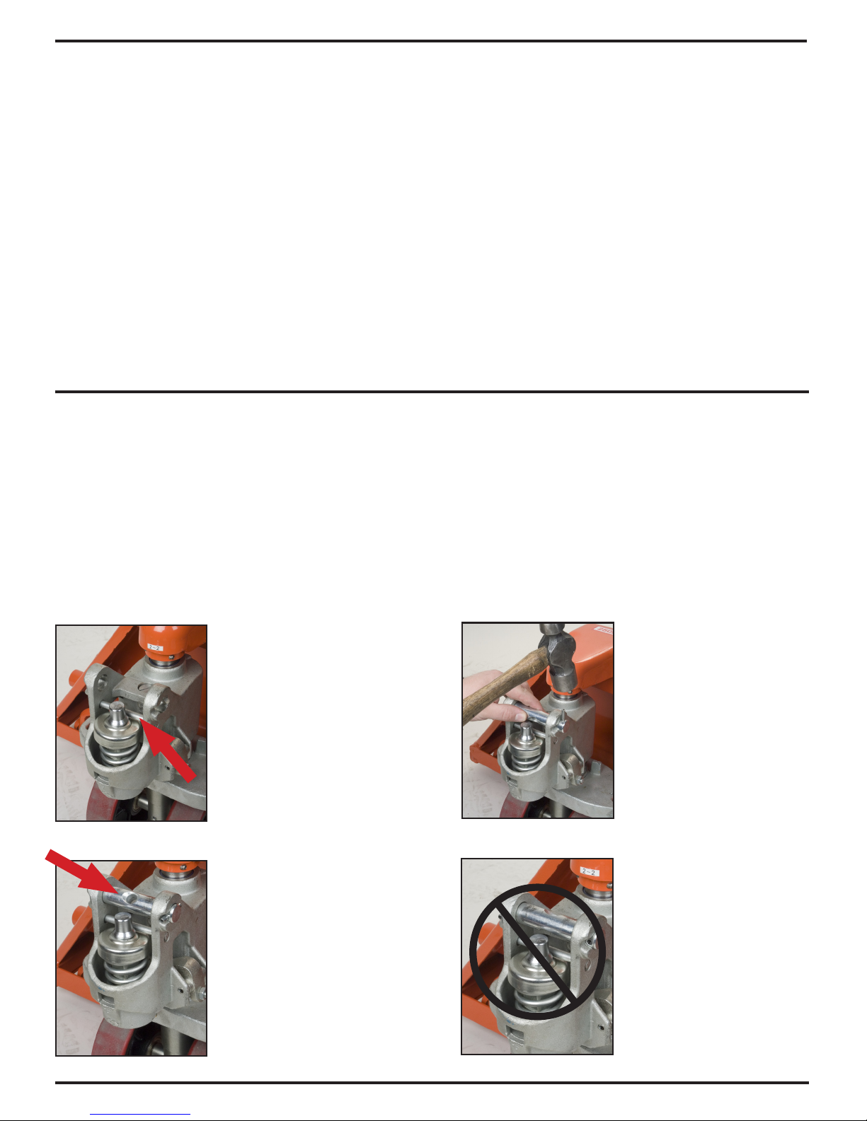
Align handle holes with pump
housing holes and push through
handle pin (see red arrow)
Make sure that handle pin is
completely through the handle
and resting on the other side.
Pull down on the handle to
release the tension on the safety
pin. CAREFULLY remove the
safety pin.
Feed the chain and nut first back
inside the handle THROUGH the
handle pin’s center hole.
***IMPORTANT - TIP ***
Release the up/down lever to
its lowest position to make the
process easier.
Once the chain is in the proper
position, check to see that it
moves freely and that it is not
obstructed.
Using both hands,
push on the valve
cam to raise the
hook inside the
housing and feed
the end of the
chain in the cam.
(see image at
right)
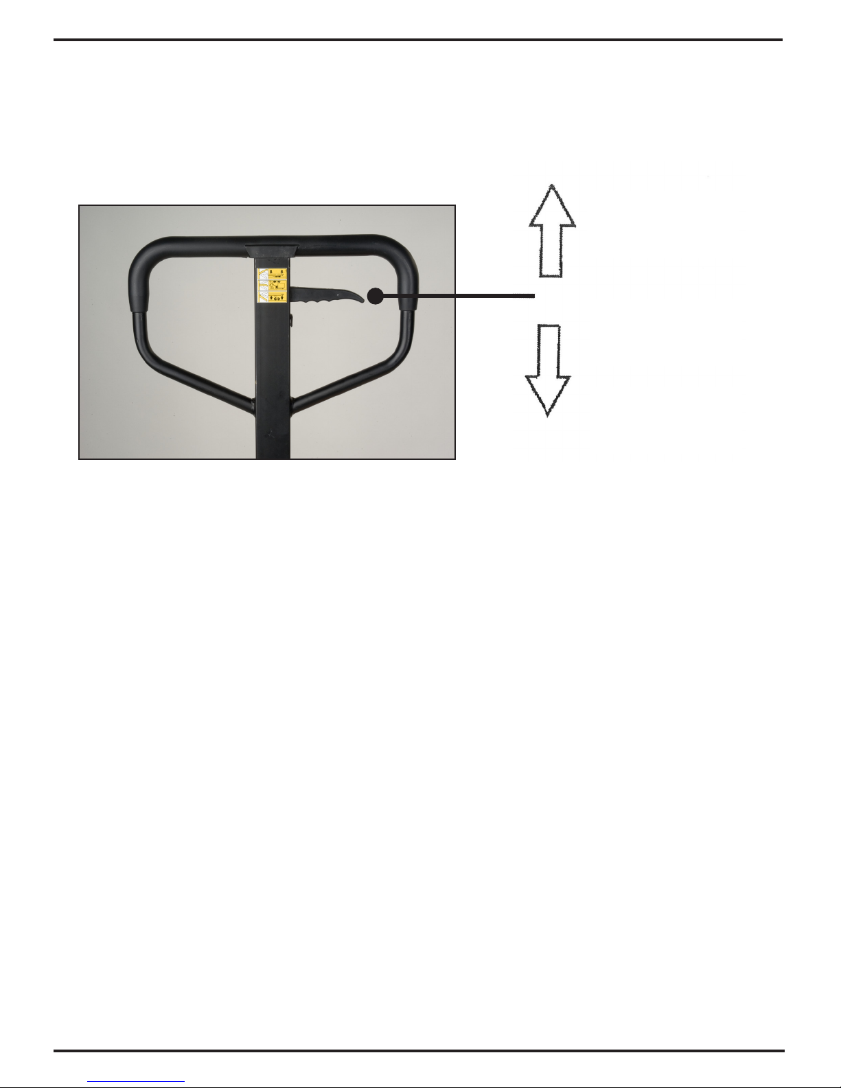
Pump the lever a few times to
raise the forks. Put the up/down
lever to its NEUTRAL position.
Using a 14mm wrench and a
flat screwdriver, adjust the valve
cam so that the forks don’t lower
or rise (if handle is pumped) at
this position.
*** IMPORTANT - FINAL CHECK ***
Test all the features of the pallet
truck before this step. The handle
should be pumped with full strokes
to prime and eliminate air in the
system. The up/down lever should be
checked at the handle’s lowest posi-
tion for this puts the most tension
on the chain. Once the pallet truck is
adjusted properly and is performing
well, drive in the second spring pin
using a hammer.
5. 6.
7. 8.
9. 10.
11. 12.

OPERATING PALLET TRUCK
To raise the forks, place handle lever in UP position (bottom part of the handle slot).
See Figure 2.
Figure 2
To lower forks, pull lever to DOWN position (upper part of the slot).
To freely move the handle, set the lever in NEUTRAL (center notch of the slot).
To lift a load:
1. Lower forks to lowest position.
2. Insert forks under load or into pallet.
3. Place lever in UP position (bottom part of the slot).
4. Move handles up and down until forks reach desired height.
To move a load:
1. Place lever in NEUTRAL position (center notch of the slot).
2. Pull or push to desired location.
To lower a load:
1. Pull lever to the DOWN position (upper part of the slot).
2. Pull forks away from load.
DOWN
NEUTRAL
UP

TECHNICAL PARAMETER
Model No. MN648 MN059
Capacity 5500 lbs. 5500 lbs.
2500 kg 2500 kg
H - Maximum
Raised Height
7 1/2" 7 1/2"
190 mm 190 mm
S - Lowered Height
3" 3"
75 mm 75 mm
L - Fork Length
42" 48"
1070mm 1220mm
E - Fork Width 6 1/4" 6 1/4"
160 mm 160 mm
B - Fork Outside
Distance
27" 27"
685 mm 685 mm
Diameter of the
steer wheel
7" x 2" 7" x 2"
180 mm x 50 mm 180 mm x 50 mm
Diameter of the
load wheel
3" x 3 5/8" 3" x 3 5/8"
74 mm x 93 mm 74 mm x 93 mm
1214
421.5
105
105
384

TROUBLESHOOTING
Possible problems could arise in the operation of your hydraulic pallet truck. Their probable cause(s) and
corrective action(s) follow:
Condition Probable Causes Corrective Action
Hydraulic unit does
not lift
Oil low in tank Make sure there is no till leakage from valve and add oil.
Relief valve not seated properly or air in the
system See “Cleaning Relief Valve" in this manual.
Defective pressure seal in main cylinder Consult authorized service centre.
Relief valve not adjusted properly Adjust valve by pressure adjustment screw
Once lifted truck
lowers by itself
Relief valve not seated properly See “Cleaning Relief Valve" in this manual.
Defective pressure seal in main cylinder Consult authorized service centre
Relief valve not adjusted properly Adjust valve by pressure adjustment screw
Oil leakage Consult authorized service centre
Fork does not lower
Cam chain broken Replace cam chain.
UP-DOWN cam nut out of adjustment Refer to “Adjusting UP-DOWN Cam" in this manual.
Broken fork rods and linkage Consult authorized service centre
Cam chain lock-nut fallen off Replace cam chain lock-nut
Lever does not set at
NEUTRAL position Relief valve not adjusted properly Adjust valve by pressure adjustment screw
Cleaning Relief Valve
Over time, relief valve may become clogged with debris and will not work properly.
To clean relief valve, flush the hydraulic system as follows:
Hold the UP/DOWN lever to the DOWN position and move the handles up and down several times.
Adjusting UP-DOWN Cam
DO NOT adjust the up/down
lever control using the lock
nut at the end of the handle
chain. If nylon locking threads
are removed from the screw
threads, rolling vibration will
cause the nut to unscrew and
fall off, leaving the up/down
lever unusable.
Use proper set screw
and lock nut adjustment
located on the side of the
pump. This feature was
designed to ease the pallet
truck adjustment.
Tools required are:
flat screwdriver and a
14mm wrench.

HYDRAULIC HAND PALLET TRUCK ASSEMBLY AND PARTS LIST
No. Order No. DESCRIPTION Qty. No. Order No. DESCRIPTION Qty.
B1 MN319 Handle Assembly 1 B24 GB879-86 Spring Pin 5X28 2
B2 MN977 Steer Wheel Shaft 1 B25 SYBC.5-06 Shaft 16X85 2
B3 GB5782-86 Bolt M8X55 1 B26 DF-04 Shaft 20X152 2
B4 MJ584 Bearing 8111 1 B27 GB879-86 Spring Pin 5X35 2
B5 BF-03 Supporting Base 1 B28 AF-04 Roll Ring 4
B6 GB879-86 Spring Pin 5X32 2 B29 MJ635 Shaft 20X122 2
B7 GB894-86 Ring For Axle 55 1 B30 MJ585 Spring Pin5X32 2
B8 MN304 Nylon Steer Wheel 2 B31 AF.7-03 Frame of Wheel 2
B9 MK984 Bearing 60204 8 B32 GB879-86 Spring Pin 5X32 8
B10 MN978 Half Ring 4 B33 SYBC.5-09 Shaft 20X95 4
B11 MN979 Washer 2 B34 AF.7-04 Nog of Wheel 4
B12 MJ591 Ring For Axle 20 2 B35 MN330 Nylon Load Wheel 2
B13 MN310 Dust Cap 2 B36 GB5782-86 Bolt M6X50 2
B14 MN302 Handle Pin 2 B38 MN306 Entry Roller 2
B15 GB1152-79 Oiler M6 6 B39 MK984 Bearing 2
B16 GB879-86 Spring Pin 5X28 2 B40 BF.4-00 Fork Frame 1
B17 AF.7-05 Joint 2 B42 GB70-85 Bolt M6X12 1
B18 DF-01 Pin 16X44 2 B43 BF.3-00 Rocker Arm 1
B19 AF.7B.1-00 Straight Tappet 1 B44 GB889-86 Lock Nut M8 1
B20 AF-02 Long Shaft 1 B45 AF.7-01 Wheel 80/74X70 4
B21 GB893-86 Ring For Hole25 2
B22 GB1155-74 Oiler 6 4
B23 AF-10 Roll Sheath 2

PUMP ASSEMBLY AND PARTS LIST
No. Order No. Description Qty. No. Order No. Description Qty.
B101 DF.1-01a Blade Spring 1 B128 BF.2-5 Spring 1.2X9.8X22 1
B102 GB879-86 Spring Pin 4X30 2 B129 AF.2-7 Strike Pin 1
B103 DF.1-02 Roller 1 B130 GB3452.1-82 O-Ring 7X1.8 1
B104 GB879-86 Spring Pin 4X20 1 B131 AF.2-06a Seat of Strike Pin 1
B105 GB879-86 Spring Pin 6X30 1 B132 GB3452.1-82 O-Ring 8X2.65 1
B106 GB879-86 Spring Pin 4X20 1 B133 GB73-85 Bolt M6X25 1
B107 DF.1-03 Handle 1 B134 GB6170-86 Nut M6 1
B108 BF.1.1-00 Handle Tube 1 B135 AF.2-8a Lever Plate 1
B109 DFI.2-04 Shaft 1 B136 CN.2-28 Bolt M10X1 1
B110 MN309 Spring Pin 3X20 1 1 B137 CN.2-27 Spring 2X8X16 1
B111 CN.2-13 Pressure Roller 1 B138 CN.2-26 Ball Base 1
B112 CSB10 Bush 1220 1 B139 GB308-77 Ball 5 1
B113 DF.1.2-00 Pull Pole 1 B140 BF.2-3 Pin 8X58 1
B114 SF-1 Bush SF-1F2015 2 B141 UHS31.5 Y-Ring 31.5 1
B115 MN321 Chain C-6-9-04A 1 B142 GB3452.1-82 O-Ring 65X2.65 1
B116 MN324 Lock Nut M5 1 B143 BF.2-2a Cylinder Cap 31.5 1
B117 GB879-86 Spring Pin 5X35 2 B144 GB3452.1-82 O-Ring 31.5X3.55 1
B118 BF-01 Shaft 1 B145 DH31.5 Dust Ring 31.5 1
B119 JF.1-17 Plug M20X1.5 1 B146 MN322 Steel Ball 19.05 1
B120 JB982-77 Copper Washer 20 2 B147 MN362 Piston 1
B121 AF.2-9 Spring 1 B148 MN363 Spring Cap 1
B122 SYBC2-07 Spindle of Valve 1 B149 MJ575 Spring 1
B123 SYBC.2-08 Seat of Valve 1 B150 DH20 Dust Ring 18 1
B124 GB308-77 Ball 6.35 1 B151 UHS18 Y-Ring 18 1
B125 BF.2.1-00 Base 1 B152 AF.2-4 Piston Rod 1
B126 JB982-77 Copper Washer 10 2 B153 GB894.1-86 Ring For Axle 8 1
B127 CN.2-17 Plug M10X1 2 A MN320 Pump Assembly 1
B MN464 Control Valve Assembly 1
A
B
This manual suits for next models
1
Table of contents
Other Kleton Truck manuals