DAF LF45 Series Instructions for use

©200515 1-1
Maintenance intervals
MAINTENANCE SCHEDULE
ΛΦ45/55 series
4
1. MAINTENANCE INTERVALS
1.1 MAINTENANCE SCHEDULE
The service intervals stated in the maintenance
schedule are based on use of the oils and fuels
specified by DAF.
1. Automatic gearboxes are subject to different
changing intervals; see maintenance
schedule notes. Extended changing interval
not permitted for ZF 6S-850 gearbox.
2. Changing interval for 1132 rear axle
450,000 km max.
+
+
Maintenance
schedule
LF45
LF55
1x per YEAR
G000318
X service Y service
40.000 km
40.000 km
40.000 km
1 year
max. 100.000 km
1 year
max. 100.000 km
1 year
max. 150.000 km
3 year
max. 180.000 km
3 year
max. 300.000 km
3 year
max. 450.000 km
1 year
max. 100.000 km
1 year
max. 100.000 km
1 year
max. 150.000 km
2 year
max. 120.000 km
3 year
max. 300.000 km
3 year
max. 300.000 km
Ext.
Ext.
Ext.
(1)
(2)

MAINTENANCE SCHEDULE
2-2 ©200515
Maintenance activities
4
ΛΦ45/55 series
2.2 OVERVIEW OF ANNUAL MAINTENANCE ACTIVITIES
ANNUAL MAINTENANCE ACTIVITIES (Y-SERVICE)
"Correct, if necessary, after inspection"
CAB AND ELECTRICAL SYSTEM
O Check pedal rubbers
O Check whether the latest version of the ITS manual is kept in the cab
O Replace the cab filter element - See note 1 Replaced O Yes O No
O Check the fluid level of the cab tilting pump
O Check cab fastening
ENGINE, COOLING SYSTEM AND FUEL SYSTEM
O Replace the air filter element
O Check the air inlet dust trapping valve
O Check the vibration damper (vulcanised version)
O Check/adjust the valve clearance - See note 4 Done O Yes O No
O Check the coolant freezing point
O Change the coolant - See note 5 Changed O Yes O No
O Remove the fuel fine filter
STEERING GEAR AND BRAKE SYSTEM
O Check the steering ball joints
O Replace the air dryer filter element
O Check the brake cylinder fastening
O Check/adjust the load-dependent control valve
O Replace the steering gear filter element if the vehicle is equipped
with the RAS-EC system - See note 6 Replaced O Yes O No
O Replace the steering gear high-pressure filter if the vehicle is
equipped with the RAS-EC system - See note 6 Replaced O Yes O No
DRIVE AND CHASSIS
O Change the differential oil - See note 2 Changed O Yes O No
O Change the hub oil - See note 2 Changed O Yes O No
O Check operation of the differential lock
O Check the drive shaft play
O Check attachment of the clamp of the drive shaft universal joint
O Adjust the crown wheel guide bolt in case of a 5.12 rear axle
O Check for noticeable wheel bearing play in case of a 5.10, 5.12,
5.14 and 8.20 rear axle - See note 1 Done O Yes O No
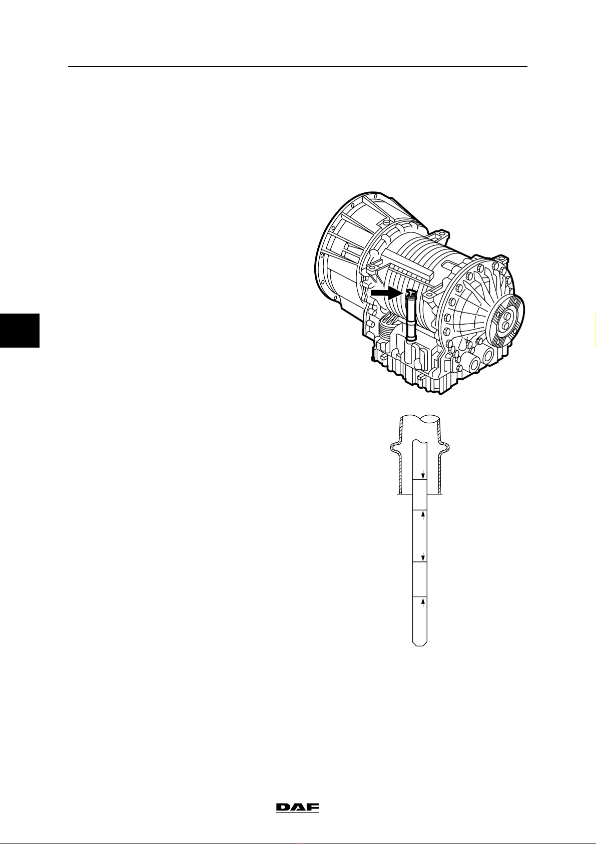
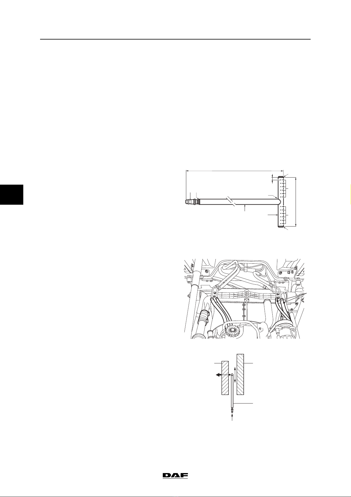
O Change the gearbox oil - See note 3 Changed O Yes O No
O Replace the grease of grease-lubricated hubs, F36 and F48 front
axles - See note 1 Replaced O Yes O No
O Check the fifth wheel
O Check the trailer coupling
O Check superstructure attachment
O Lubricate according to Y-service lubrication schedule
OTHER ACTIVITIES
O Check whether there are any field actions that still need to be performed on the vehicle

EXPLANATORY NOTES ON THE MAINTENANCE ACTIVITIES
3-30 ©200515
Inspection and adjustment
5
ΛΦ45/55 series
Checking hot oil level
1. Bring the gearbox up to operating
temperature (approx. 71C - 93C).
2. Remove the dipstick when the engine is
idling and wipe it clean with a lint-free cloth.
Note:
To take the dipstick out of the holder, the
sealing cap must be held while the dipstick is
turned anti-clockwise.
3. Put the dipstick back.
4. Remove the dipstick and check the oil level.
5. The oil level should be between the "Hot
add" and "Hot full" marks.
6. Clean the dipstick with a lint-free cloth and
put it back.
7. Remove the dipstick and check the oil level
again.
8. Oil needs to be added when the oil level is
below the "Hot add" mark.
9. Oil needs to be drained when the oil level is
above the "Hot full" mark.
Note:
The oil level must be checked at least twice.
When there are differences between the
measurements, check the bleeder for
clogging.
HOT
FULL
COLD
FULL HOT
ADD
COLD
ADD
W 3 03 099

EXPLANATORY NOTES ON THE MAINTENANCE ACTIVITIES
3-32 ©200515
Inspection and adjustment
5
ΛΦ45/55 series
3.38 CHECKING GREASED WHEEL HUBS FOR LEAKS
1. Check the wheel hubs for leaks.
Note:
For maintenance-free wheel hubs:
If there are serious grease marks on the
brake disc side of the wheel hub, this could
indicate excessive use of assembly grease
on new or recently assembled wheel hubs.
On wheel hubs that were not assembled
recently, serious grease marks could
indicate a leak in the seal.
Checking greased wheel hubs for leaks,
1132 axle
1. Check the wheel hubs for leaks.
Note:
If there are serious grease marks on the
brake disc side of the wheel hub, this could
indicate excessive use of assembly grease
on new or recently assembled wheel hubs.
On wheel hubs that have not been
assembled recently, serious grease marks
could indicate a leak in the seal (1). This
means that the entire hub unit must be
replaced.
Serious oil leakage on the driven rear axle
hubs could indicate that the O-ring (2) is not
sealing correctly.
If there is an oil leak the hub unit should be
dismantled to remedy the problem.

©200515 4-3
Removal and installation
EXPLANATORY NOTES ON THE MAINTENANCE ACTIVITIES
ΛΦ45/55 series
5
4.3 REMOVAL AND INSTALLATION, LUBRICATING OIL FILTER
To prevent skin injury, avoid
unnecessary contact with the
drained lubricating oil.
Be careful when changing the oil.
Hot oil may cause serious injuries.
Removing the lubricating oil filter
1. Place a tray beneath the lubricating oil filter.
2. Clean the area surrounding the filter element
if this is very dirty.
3. Remove the filter element by turning it anti-
clockwise. Collect the oil that comes out.
4. Remove the O-ring if it has not been
removed already.
Installing the lubricating oil filter
1. Lightly oil the filter element sealing ring.
2. Fill the filter element with clean oil. Use the
specified oil.
3. Fit the filter element onto the housing.
Tighten the filter element until the sealing
ring abuts. Tighten the filter element a further
•to 1 turn by hand.
4. Run the engine for a short time and check
that the lubricating oil filter is correctly
sealed.
5. Check the oil level and correct if necessary.
Use the specified oil.
}
}
G0 00 207

EXPLANATORY NOTES ON THE MAINTENANCE ACTIVITIES
4-4 ©200515
Removal and installation
5
ΛΦ45/55 series
4.4 REMOVAL AND INSTALLATION, FUEL FINE FILTER
When removing the fuel fine filter, a
quantity of fuel will escape. Collect
the fuel and avoid the risk of fire.
Removing the fuel fine filter
1. Place a container beneath the fuel fine filter
and remove the filter.
Note:
The fuel fine filter is a disposable filter and
must therefore not be cleaned and re-used.
Installing the fuel fine filter
Note:
Do not fill the fine filter with fuel until it has
been fitted. The fine filter is filled with fuel by
the primer pump after it has been fitted. This
considerably reduces the risk of dirt getting
into the fuel system.
1. Check by hand whether the coupling piece
for the filter attachment is securely attached.
2. Lightly lubricate the filter sealing ring with
clean engine oil.
3. Fit the filter element onto the housing.
Tighten the filter element until the sealing
ring abuts. Tighten the filter element a further
∂to •turn by hand.
4. Bleed the fuel system. See "Inspection and
adjustment".
5. Start the engine and check the fuel system
for leaks. If necessary, retighten the filter by
hand.
}
G0 00 201
i400964

©200515 5-13
Draining and filling
EXPLANATORY NOTES ON THE MAINTENANCE ACTIVITIES
ΛΦ45/55 series
5
Filling the gearbox
1. Clean the drain plugs, provide them with new
sealing rings and fit them, tightening them to
the specified torque, see "Technical data".
2. Fill the gearbox through the dipstick holder
with the specified quantity of oil; see
"Technical data".
3. Start the engine and run it at idling speed.
4. Tighten the bleed screw (2) to the specified
torque, if only gearbox oil escapes. See
"Technical data".
5. With the engine running at idling speed, top
up gearbox oil until the oil level is between
the "Cold add" and "Cold Full" marks.
6. Check the oil level. See "Inspection and
adjustment".
Allison MD3060 automatic gearbox
To prevent skin injury, avoid
unnecessary contact with the
drained oil.
Draining the gearbox
1. Place the vehicle on a flat and level surface.
2. Bring the gearbox to operating temperature
(approx. 71C - 93C) to allow the oil to drain
more quickly and more fully.
3. Remove the drain plug (1) from the gearbox
oil sump.
4. Remove the oil filters (2). See "Removal and
installation".
HOT
FULL
COLD
FULL HOT
ADD
COLD
ADD
W 3 03 099
}
V300371
2
1

EXPLANATORY NOTES ON THE MAINTENANCE ACTIVITIES
5-14 ©200515
Draining and filling
5
ΛΦ45/55 series
Filling the gearbox
1. Clean the drain plug (1), fit a new sealing ring
and tighten the plug to the specified torque;
see "Technical data".
2. Fit the oil filters (2). See "Removal and
installation".
3. Fill the gearbox through the dipstick holder
with the specified quantity of oil; see
"Technical data".
4. Check that the oil level reaches the "Cold
full" mark.
Note:
To take the dipstick out of the holder, the
sealing cap must be held while the dipstick is
turned anti-clockwise.
5. Check the oil level using the selector keypad.
See "Inspection and adjustment".
W 3 03 098
HOT
FULL
COLD
FULL HOT
ADD
COLD
ADD
W 3 03 099

©200515 6-1
Cleaning
EXPLANATORY NOTES ON THE MAINTENANCE ACTIVITIES
ΛΦ45/55 series
5
6. CLEANING
6.1 CLEANING THE BATTERY TERMINALS
Avoid sparks and open flames in the
vicinity of batteries. Battery acid is
an aggressive fluid.
In the event of contact with the skin:
rinse the skin with plenty of water for
a sustained period. If redness or
pain persists, consult a doctor.
Remove any clothing affected and
rinse with water.
In the event of contact with the eyes:
rinse with plenty of water for at least
15 minutes and consult a doctor.
If swallowed: do NOT induce
vomiting. Rinse the mouth, drink two
glasses of water and consult a
doctor.
In the event of inhalation: get fresh
air, rest and consult a doctor.
1. Disconnect the earth lead from the battery
terminal.
2. Disconnect the positive lead from the battery
terminal.
3. Clean the battery terminals, battery cables
and the top of the battery (oxide and dirt
discharge the battery).
4. If the top of the battery has acid on it, it
should be rinsed with water.
5. Check the fastening of the earth cable
connection to the chassis. Grease the
connection with petroleum jelly.
6. Check the connection between the cable and
the fuse holder located behind the batteries;
see the arrow in the illustration. Clean the
connection and grease it with petroleum jelly.
7. Fit the positive lead to the battery terminal.
8. Fit the earth lead to the battery terminal.
9. Grease the battery terminals with petroleum
jelly.
10. Check the routing and attachment of the
battery cables.
}
G0 00 227

EXPLANATORY NOTES ON THE MAINTENANCE ACTIVITIES
6-2 ©200515
Cleaning
5
ΛΦ45/55 series
6.2 CLEANING THE EXTERIOR OF RADIATOR AND AIR COOLER
Inhalation of dust may have serious
consequences for your health.
Take the necessary precautions,
such as wearing goggles and a
facemask.
Note:
With the aid of a simple tool, the radiator and the
air cooler can be blow-cleaned.
The tool (radiator cleaner) cannot be ordered
from DAF. It should be manufactured by yourself
according to the drawing.
Key to drawing:
1. If the vehicle has air conditioning, loosen the
support of the refrigerant pipes (1) on the
radiator and remove the condenser from the
air cooler supports. Push the condenser as
far as possible forwards.
2. Insert the radiator cleaner (3) between the air
cooler (1) and radiator (2) from underneath,
with the air holes facing the air cooler (1).
3. Apply air pressure to the radiator cleaner (3)
and continue blow-cleaning the air cooler (1)
until no more dirt comes out.
}
100mm
5mm
2
1150mm
2
4
35
5
4
1
1
M2108
1 Solder up
2Solder
3 Quick-release coupling for air hose
4 Steel pipe, 10 mm
56x1.5 mm between holes, with a
centre-to-centre distance between the
holes of 7 mm, drilled on one side
i400824
1
12
3
M201351
P

©200515 7-1
Lubrication
EXPLANATORY NOTES ON THE MAINTENANCE ACTIVITIES
ΛΦ45/55 series
5
7. LUBRICATION
7.1 LUBRICATING ACCORDING TO Y-SERVICE LUBRICATION SCHEDULE
Note:
The lubricating points marked below with an (S)
indicate that the lubricating point is positioned on
both the left-hand and right-hand side of the
vehicle.
Lubricating stub axles (S), general
1. To make sure that the grease can penetrate
adequately, the stub axles should be
lubricated in unloaded condition. The front
axle should therefore be completely jacked
up; make a complete steering movement
from left to right during greasing.
2. Lubricate the stub axles until grease comes
out.
F36, F48 and F60 (S) front axles
1. The F36 and F48 front axles have a grease
nipple on the top side and the underside. The
F60 front axle has a grease nipple only on
the underside.
S7 00 545
S7 00 591
S7 00 590

EXPLANATORY NOTES ON THE MAINTENANCE ACTIVITIES
7-2 ©200515
Lubrication
5
ΛΦ45/55 series
152N (S) front axle
1. The 152N front axle has a grease nipple on
the top side and underside.
G000189
Other manuals for LF45 Series
5
This manual suits for next models
1
Table of contents
Other DAF Truck manuals
Popular Truck manuals by other brands

Manitou
Manitou MT732ST38 Operating and safety instructions

FCA US
FCA US RAM 2500 2019 manual

Southworth
Southworth PT-33-M Maintenance manual & operator instructions

Motrec
Motrec T-448N Operator and maintenance manual

Komatsu
Komatsu 730E Operation & maintenance manual

RAM Commercial
RAM Commercial 2018 PROMASTER user guide