TORQUE GUN THRILL jGUN Guide

STAY SAFE
THANK YOU FOR PURCHASING THIS REVOLUTIONARY TORQUE/TENSION SYSTEM
PLEASE CALL YOUR HYTORC REPRESENTATIVE TO SCHEDULE A FREE TRAINING THAT WILL
HELP YOU GET THE MOST OUT OF THIS ADVANCED BOLTING SYSTEM.
OPERATING CD: Please show the enclosed CD to your staff before each tool use to familiarize them
with the tools.
FREE SAFETY TRAINING: To ensure safe operation, please request the FREE Safety Training
before use by calling your local HYTORC Representative 1-800-367-4986 or www.hytorc.com.
We recommend safety training every 6 months. These trainings are free of charge. Just call us.
PLEASE READ THE SAFETY INSTRUCTIONS HEREIN.
SYSTEM INSPECTION: Before any use, please inspect the entire tool system, including hoses, gauge,
sockets and backup wrenches. Do not use kinked hoses, oversized or heavily worn sockets, backup
wrenches, damaged tools, pumps, connectors, or gauges. Connect system to operate from a safe
distance. Ensure fasteners are in good shape. Check out tool functioning with drive or hex ratchet
turning in one direction only and check out gauge from a safe distance that needle is on zero at
no pressure and at 10,000 psi at high pressure. Keep high pressure on and check system visu-
ally for leaks. Please keep in mind that hydraulic tools are very strong and work at high pressure.
HANDS-FREE BOLTING: The tool you have purchased permits hands-free operation from a safe
distance in conjunction with a HYTORC Washer™. We recommend the use of a HYTORC Washer™
to avoid nger-pinching, over-crowded sites and to ensure hands-free bolting at least on all vertical
and inverted applications, while eliminating improvisation and the use of reaction members or
backup wrenches. Otherwise, set up the tool in a way that it does not have to be held by hand.
For more information, please contact us at 1-800-367-4986 or www.hytorc.com.
HANDS-FREE WASHER APPLICATION: Make sure the drive and the tool are locked on securely.
FREE ANNUAL TOOL INSPECTION: With the purchase of HYTORC, you have the right to a FREE
annual tool inspection which includes free seals, springs, connectors, and free lubrication. In case of
damaged or worn parts, the rst inspection within 12 months of purchase is free of charge. There-
after, you will be informed of any cost prior to replacement. Any part replaced and charged by us
will be sent to you for your inspection upon request when P.O. is issued.
FREE LOANER TOOLS: In case of tool failure during the warranty or rental period, please contact
your local HYTORC Agent for a free loaner tool - 24/7.
HOSE REPLACEMENT: We recommend replacing hydraulic hoses and oil every (3) three months.
PLEASE WEAR REQUIRED SAFETY ATTIRE and use common sense during operation.
HELP: If you require any further assistance, please call your local HYTORC Representative or
1-800-FOR-HYTORC (1-800-367-4986), on the web at www.hytorc.com - 24/7! It’s live!
PLEASE REVIEW THESE SAFETY
TIPS BEFORE EVERY TOOL USE
No. Safety 1-2-1009

THRILL™
OPERATIONAL AND SPARE PARTS MANUAL
CONTENTS
Warranty 4
jGun Overview 5
jGun Safety 6
jGun Setup and use 7
THRILL Gun Overview 9
THRILL Gun Specifications 10
Torque/Speed Settings 11
High Speed Operation (Impact) 11
Maximum Torque Operation 12
Switching Settings 13
Typical Usage 14
FRL (Filter, Regulator, Lubricator) Overview 16
FRL Setup and Use 18
FIGURES
Figure 1: THRILL Gun with Socket 9
Figure 2: THRILL Gun Dimensions 10
Figure 3: Torque Operation Settings - High Speed (Impact)/Maximum Torque 11
Figure 4: Holding the THRILL in the High Speed (Impact) Setting 11
Figure 5: Safety Position for THRILL Gun in Maximum Torque Setting 12
Figure 6: Switching from Maximum Torque to High Speed (Impact) 13
Figure 7: High Speed (Impact) Rundown 15
Figure 8: Maximum Torque Demonstration 15
Figure 9: FRL Unit (Shown without silencer) 16
Figure 10: FRL Unit 19
Figure 11: Detaching FRL Reservoir 19
Figure 12: FRL Unit, Lubricator 2/3rds Full of Oil 20
Figure 13: Adjusting FRL Regulator 21
Figure 14: Adjusting FRL Oil Flow 22
TABLES
Table 1: Bolt Torque Specications 8
Table 2: THRILL Gun Specifications 9
3
BREAKTHROUGH PRODUCTS FOR INDUSTRIAL BOLTING

4BREAKTHROUGH PRODUCTS FOR INDUSTRIAL BOLTING
The jGun has a one year limited warranty. Every TORQUE GUN tool is tested before leaving the fac-
tory and is warranted to be free from defects in workmanship and materials. TORQUE GUN will repair
or replace, without charge, any tool which upon examination proves to be defective in workmanship or
materials for one (1) year after the date of purchase. This warranty does not cover damage from repairs
made or attempted by other than TORQUE GUN authorized repair facilities.
The repair and replacement remedies described herein are exclusive. In no event shall TORQUE GUN be
liable for any incidental, special, or consequential damages, including loss of prots.
This warranty is exclusive and in lieu of all other warranties or conditions, written or oral, expressed or
implied for merchantability or tness for particular use or purpose.
This warranty gives you specic legal rights. You may also have other rights that vary from state to state
and province to province. In those states that do not allow the exclusion of implied warranties or limita-
tion of incidental or consequential damages, the above limitations or exclusions may not apply to you.
If you have questions about the warranty, contact our customer service center at
201-828-5270.
WARRANTY
jGUN OVERVIEW
The jGun pneumatic torque wrench is designed to safely and accurately deliver up to 5,200 ft-lbs of
torque onto a fastener. This is accomplished using a patented planetary gearbox torque multiplier sys-
tem and an appropriate reaction arm or HYTORC Washer™ and HYTORC Nut™. The torque multiplier
produces torque ratios of up to 1450:1 while the reaction arm or washer is used to absorb the high coun-
ter rotational force produced as the nal torque value is reached. At nal torque value, the jGun safely
stalls out, leaving the fastener tightened to specication.
Unlike impact wrenches, the jGun never transmits working torque to the operator. The torque is applied
between the fastener and the reaction surface.
This manual provides information for both the standard THRILL jGun.
5
BREAKTHROUGH PRODUCTS FOR INDUSTRIAL BOLTING

jGUN SAFETY
Only qualied personnel who have thoroughly read this document may operate this tool. Failure to safely
operate this tool may result in serious injury or death.
• Inspect all jGun components as they are removed from the shipping container. If damage is
found to any component, contact your shipper immediately. Do not use the tool.
• Failure to follow correct tool usage could result in personal injury, co-worker injury, and/or dam-
aged tools and equipment.
• Ensure your working area is clean and unobstructed before beginning work.
• jGun maintenance and repair must be performed by a qualied pneumatic technician.
• Modifying a jGun or jGun accessory is dangerous and invalidates the warranty.
• Inspect the tool before each use. Replace any obviously worn or damaged parts.
• When not in use, store the jGun and jGun accessories in the plastic storage case supplied with
the tool. Do not expose the gun to high humidity or large temperature variations.
Personal Protective Equipment
• Always wear the appropriate personal protective equipment when operating a jGun including
gloves, safety goggles, hearing protection, hard hat, and safety shoes.
Air Supply Requirements
• The air supply line must be ½-inch minimum diameter to allow adequate air ow to the jGun.
• The air supply must provide a minimum of 90 psi at 30 cfm.
• Ensure that air line ttings are tight and leak free. Do not over tighten air line ttings.
• Always use the Filter Regulator Lubricator (FRL) Unit provided with the jGun. Never use a substi-
tute oiler and regulator.
• Open the air supply connected to the FRL unit and run the jGun while setting the pressure on the
regulator gauge.
• Set the air pressure to the PSI needed to achieve desired torque shown on the provided pres-
sure/torque conversion chart, also shown in Pressure / Torque Conversion Charts.
NOTE
Set the air pressure at the FRL while the tool is running as described in FRL Setup and Use.
6BREAKTHROUGH PRODUCTS FOR INDUSTRIAL BOLTING

jGUN SETUP AND USE
Proper setup and use of the jGun before and during installation ensures accurate results and safe op-
eration. The FRL Unit provided with the jGun must be used with the hose provided to ensure the tool’s
durability. See the FRL Unit Overview section below for more information.
Setting a Torque Value
1. Determine the torque value for the fastener to be tightened, as shown in the Bolt Torque Speci-
cations table on page 8.
2. Determine the air pressure needed to achieve the desired torque by consulting the Pressure/
Torque Conversion Chart provided with each tool.
3. Open the air supply connected to the FRL unit and run the torque wrench while setting the pres-
sure on the gauge.
NOTE
The torque wrench must be running while the pressure is being set. When the torque
wrench is stopped, the gauge displays a slightly higher pressure than was set with the
jGun running. This is normal, proper torque is delivered under working load.
7
BREAKTHROUGH PRODUCTS FOR INDUSTRIAL BOLTING

SAE1 SAE2
30,000PSI
ASTM 193 Grade
B7 Bolt
Gr. 7 A/F Heavy Hex
Nut Foot Pounds Estimated Load
1 inch 7/8 inch 1-7/16 inches 300 18,150 lbf
1-1/8 inches 1 inch 1-5/8 inches 425 23,690 lbf
1-1/4 inches 600 29,955 lbf
1-3/8 inches 1-1/8 inches 1-3/16 inches 700 36,990 lbf
1-1/4 inches 2 inches 800 46,776 lbf
1-1/2 inches 900 44,760 lbf
1-5/8 inches 1-3/8 inches 2-3/16 inches 1,250 53,400 lbf
1-1/2 inches 2-3/8 inches 1,500 64617 lbf
1-3/4 inches 1,600 62,400 lbf
1-7/8 inches 1,800 72,300 lbs
1-5/8 inches 2-9/16 inches 2,000 76,540 lbs
2 inches 2,200 83,100 lbs
1-3/4 inches 2-3/4 inches 2,600 89,440 lbs
2-1/4 inches 3,000 106,800 lbs
1-7/8 inches 2-15/16 inches 3,700 110,680 lbs
2-1/2 inches 2 inches 3-1/8 inches 4,000 133,200 lbs
2-3/4 inches 5,100 162,900 lbs
Table 1 - Bolt Torque Specications
The Data Above is based on bolts lubricated to manufacturer’s specifications.
Due to a variation in friction, we recommend in extreme cases to check with the
bolt manufacturer, as the chart represents a guideline only.
8BREAKTHROUGH PRODUCTS FOR INDUSTRIAL BOLTING

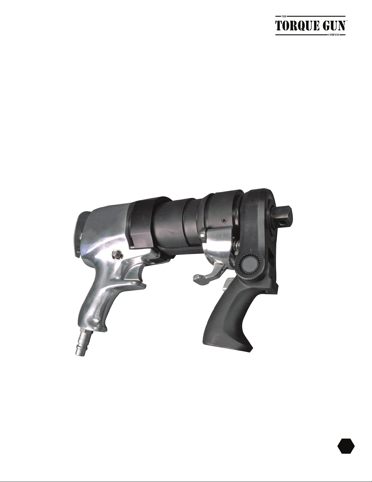
THRILL OVERVIEW
The THRILL Gun is a special implementation of the dual speed pneumatic torque wrench. These pneu-
matic tools allow the operator to rundown and tighten nuts without the hassles of installing and removing
a reaction arm. Each THRILL Gun is equipped with a special mechanism which works as a handle in high
speed (impact mode) and a reaction arm when placed in the high torque setting.
9
BREAKTHROUGH PRODUCTS FOR INDUSTRIAL BOLTING
Figure 1 - THRILL Gun with Arm in Reaction Position
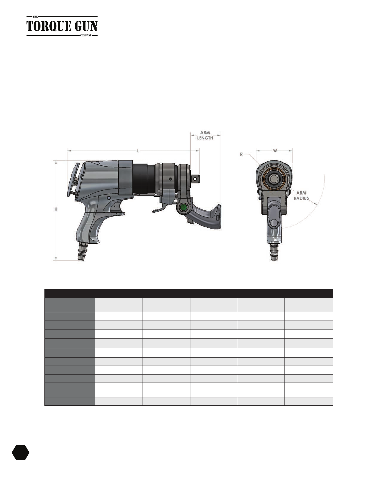
THRILL SPECIFICATIONS
General dimensions for the THRILL Gun.
Figure 2 - THRILL Gun Dimensions
MODEL THRILL-A.25 THRILL-A.5 THRILL-A.7 THRILL-A1 THRILL-A3
TORQUE RANGE 63-283 ft. lbs.
(383.7 Nm)
117-528 ft. lbs.
(715.9 Nm)
180-808 ft. lbs.
(1095.5 Nm)
252-1134 ft. lbs.
(1537.5 Nm)
685-3083 ft. lbs.
(4178.6 Nm)
DRIVE SIZE 1/2" SQ. 3/4" SQ. 3/4" SQ. 3/4" SQ. 1" SQ.
HEIGHT (H) 8.25" (21.0 cm) 8.25" (21.0 cm) 9.05” (22.0 cm) 9.05” (22.0 cm) 9.52" (24.2 cm)
LENGTH (L) 10.83" (27.5 cm) 11.25" (28.6 cm) 11.54" (29.3 cm) 11.79" (29.9 cm) 15.64" (39.7 cm)
WIDTH (W) 2.71" (6.9 cm) 2.71" (6.9 cm) 3.29" (8.4 cm) 3.29" (8.4 cm) 3.50" (8.9 cm)
RADIUS 1.12" (2.8 cm) 1.12" (2.8 cm) 1.59" (4.0 cm) 1.59" (4.0 cm) 1.75" (4.4 cm)
ARM LENGTH 2.75" (7.0 cm) 2.75" (7.0 cm) 2.75" (7.0 cm) 2.75" (7.0 cm) 3.50" (8.9 cm)
ARM RADIUS 4.19" (10.6 cm) 4.19" (10.6 cm) 4.55" (11.4 cm) 4.55" (11.4 cm) 6.18" (15.7 cm)
WEIGHT 9.18 lbs. (4.16 kg) 10.19 lbs. (4.62 kg) 13.30 lbs. (6.03 kg) 15.53 lbs. (7.04 kg) 28.70 lbs. (13.02 kg)
RUNDOWN RPM
(NO LOAD) 3393 RPM 3182 RPM 3200 RPM 3000 RPM 3500 RPM
FINAL TORQUE RPM 25 RPM 12 RPM 12 RPM 7 RPM 4 RPM
Table 2 - THRILL Gun Specications
10 BREAKTHROUGH PRODUCTS FOR INDUSTRIAL BOLTING

TORQUE SPEED SETTINGS
The THRILL Gun has two operation settings: High Speed (Impact mode) and Maximum Torque
High Speed Operation
• The THRILL Gun operates in high speed when the arm is locked into the upward position.
(Shown on the left in gure 3) The arm should be perpendicular to the body of the jGun.
• When the arm is locked in the upward position, it serves as a handle.
• Once fully engaged, the THRILL housing and square drive will begin to rotate at high speed.
• Use this feature when you want to run nuts on or off a stud quickly.
• When using the high speed feature, be sure to hold the handle rmly as the gun reaches high
RPM suddenly. (Shown in Figure 4)
Figure 3 - Torque Operation Settings, High Speed (Left) and Maximum Torque (Right)
Figure 4 - Holding the THRILL Gun in the High Speed (Impact) Setting
11
BREAKTHROUGH PRODUCTS FOR INDUSTRIAL BOLTING
Maximum Torque Operation
• The THRILL Gun functions in Maximum Torque mode when the arm is locked in the down posi-
tion. (Shown on the right in gure 3)
• When the arm is locked in the down position, it is a reaction arm.
• PLEASE KEEP YOUR HANDS OFF THE ARM WHEN USING THIS FEATURE.
• See Figure 6 for an illustration of how to hold the gun when in this setting.
• To operate in maximum torque, fully depress rear “safety plate”.
• Once “safety plate” is fully depressed, you may begin maximum torque operation.
• During operation, the square drive will move while the housing of the THRILL will remain
stationary.
• While in maximum torque mode, the THRILL behaves similar to that of a single speed jGun.
Tighten the nuts until the desired bolt load is reached.
Figure 5 - Safety Position for THRILL Gun in Maximum Torque Setting
!! CAUTION !!
KEEP YOUR HAND OFF THE REACTION ARM AREA WHEN
OPERATING IN MAXIMUM TORQUING MODE.
PERSONAL INJURY MAY OCCUR IF YOUR HAND OR ANY PORTION
OF YOUR BODY IS LOCATED BETWEEN THE REACTION ARM AND
THE REACTION POINT.
12 BREAKTHROUGH PRODUCTS FOR INDUSTRIAL BOLTING
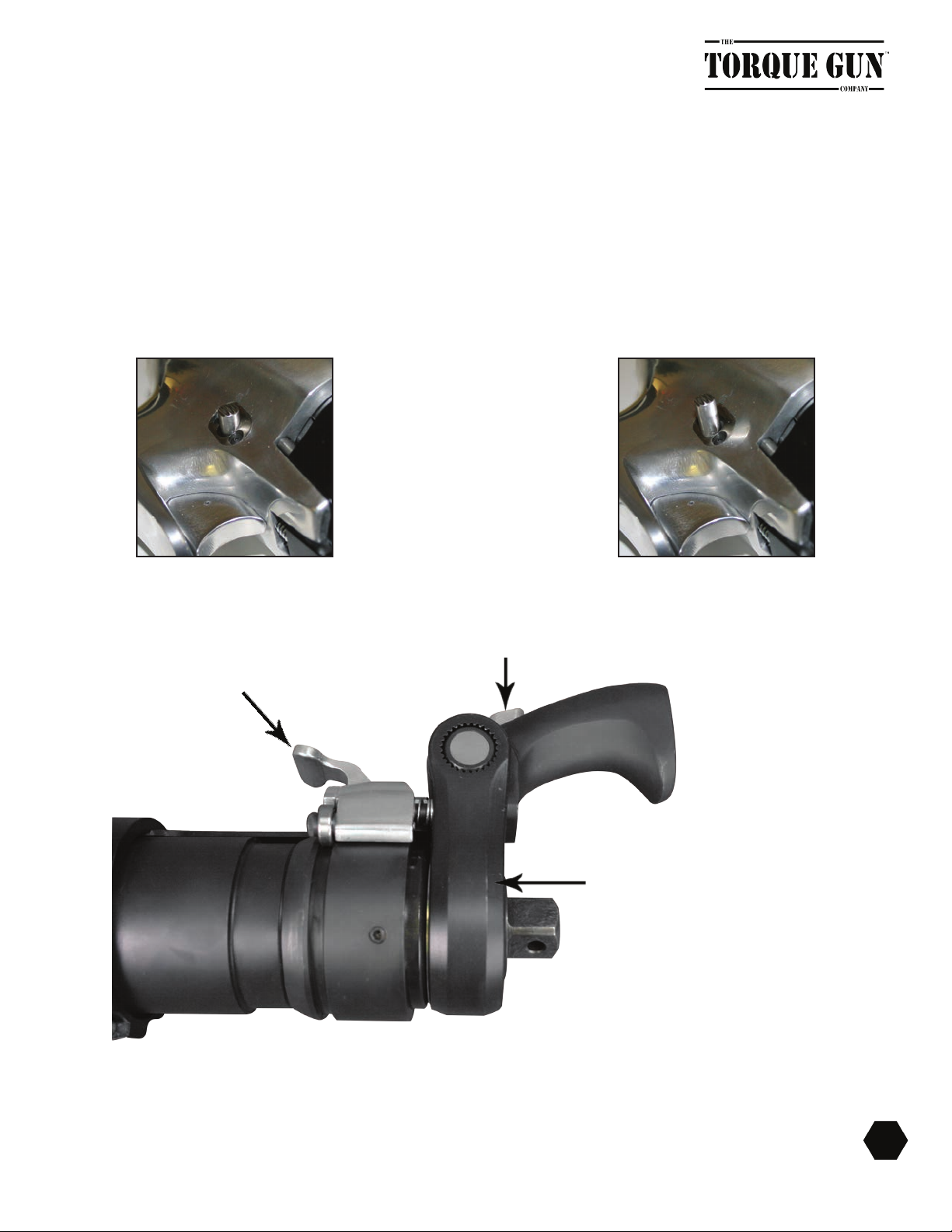
Figure 6 - Switching from Maximum Torque to High Speed (Impact)
High Speed Lever
Swivel Block
Lock Button
13
BREAKTHROUGH PRODUCTS FOR INDUSTRIAL BOLTING
Switching Settings
• Before changing torque settings, be sure that the button located on the reaction arm/handle is
fully retracted. The mechanism should not be free to move if it is fully engaged.
• Connect the appropriate air tting to the back of the THRILL Gun.
• To switch between the Maximum Torque and High Speed (Impact) settings, press the locking
button and rotate the arm (see Figure 7 on page 15) until it reaches the desired locking position
on the swivel block. These locking positions prevent the handle/arm from accidentally moving
into a different setting.
• After making sure that the handle/arm is fully engaged, press the THRILL trigger and run the gun
to make sure that you are operating in the desired speed/torque setting.
• To reverse rotational
direction push side
directional button in
and slightly upwards.
• To revert back to tighten, push
the button in and slightly down
in one motion.

NOTE
BEFORE SHIFTING BETWEEN HIGH SPEED AND MAXIMUM TORQUE MODES, MAKE
SURE THE TOOL IS COMPLETELY STOPPED. ENSURE THAT THE HANDLE/ARM IS
FULLY ENGAGED IN EITHER THE UP OR DOWN POSITION, BEFORE RESUMING OP-
ERATION
FAILURE TO FULLY ENGAGE THE TOOL MAY AFFECT THE OPERATION OF THE TOOL
AND ULTIMATELY RESULT IN THE LOSS OF CONTROL AND/OR DAMAGE TO THE
TOOL.
• If you experience any trouble shifting into a different setting, re-engage the handle/arm into the
previous setting and make sure that it is locked. Press and hold the THRILL Gun trigger for 10
seconds and release. Repeat this step until the gun shifts freely.
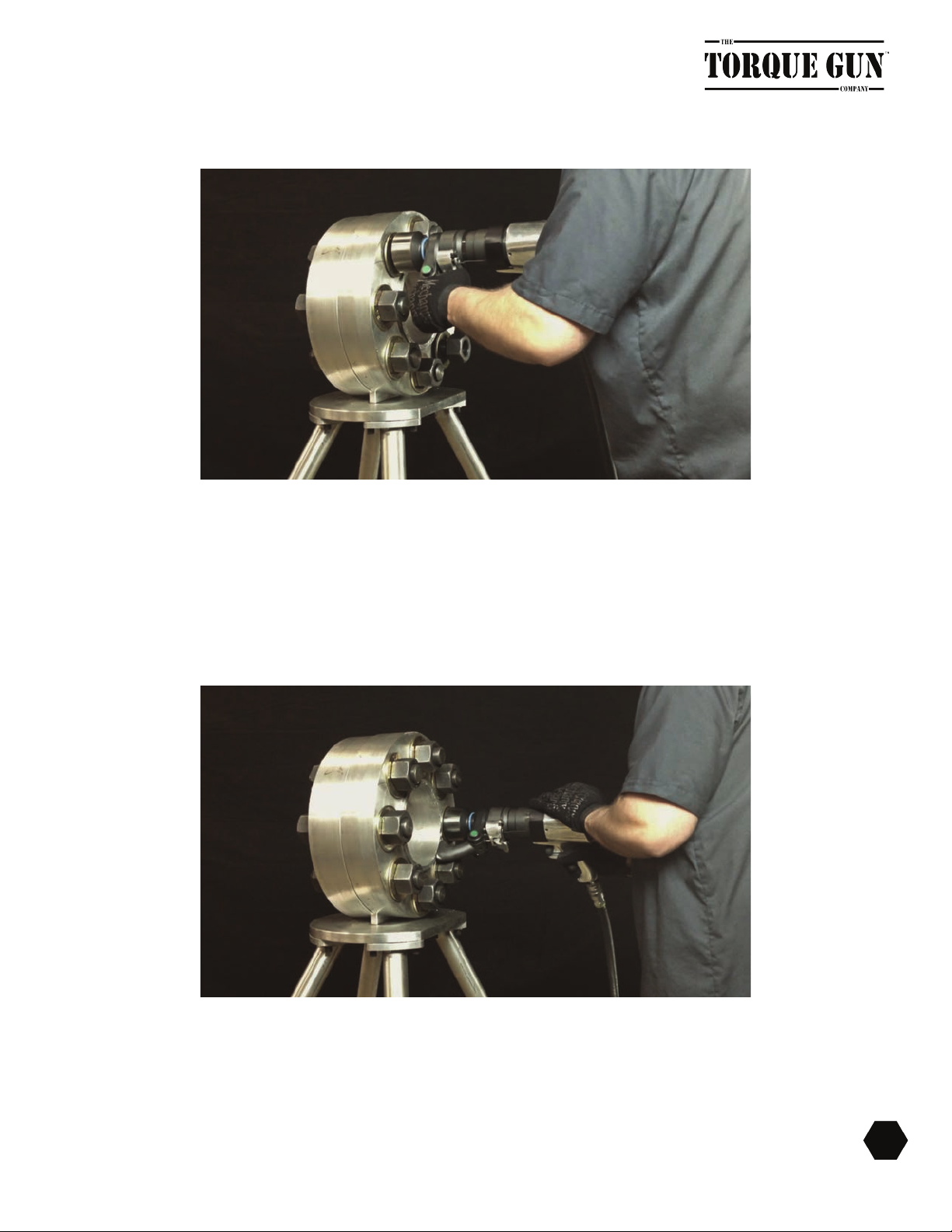
Typical Usage
The following section is a simple guideline on how to use the THRILL Gun on an application. The
gures below show the THRILL Gun being used with a demonstration ange.
• Before operating the THRILL Gun, make sure that the operator reads and understands all safety
and setup instructions. For best performance when using the THRILL Gun, use 12 point sockets
to rundown and tighten your fasteners.
• Shift the Gun into High Speed (Impact) mode by moving the arm/handle perpendicular to the
body of the THRILL Gun. Press down the lever to activate high speed mode. Make sure that the
side button on the handle is out before pressing the trigger. Run down all the nuts on the ap-
plication using the high speed setting. Remember to hold the handle rmly while operating the
THRILL Gun.
• Run the nuts down until they seat and bring the THRILL Gun to a complete stop.
14 BREAKTHROUGH PRODUCTS FOR INDUSTRIAL BOLTING
• Once the THRILL comes to a complete stop, remove the tool from the nut and change the set-
ting from High Speed (Impact) to Maximum Torque. Remember to remove your hand from the
trigger, press the locking button, and rotate the arm/handle until it locks into position (see Maxi-
mum Torque Section for clarication).
• Place the tool back on the nut for the nal torque. Fully depress rear “safety plate” and make
sure that your hands are away from the reaction arm.
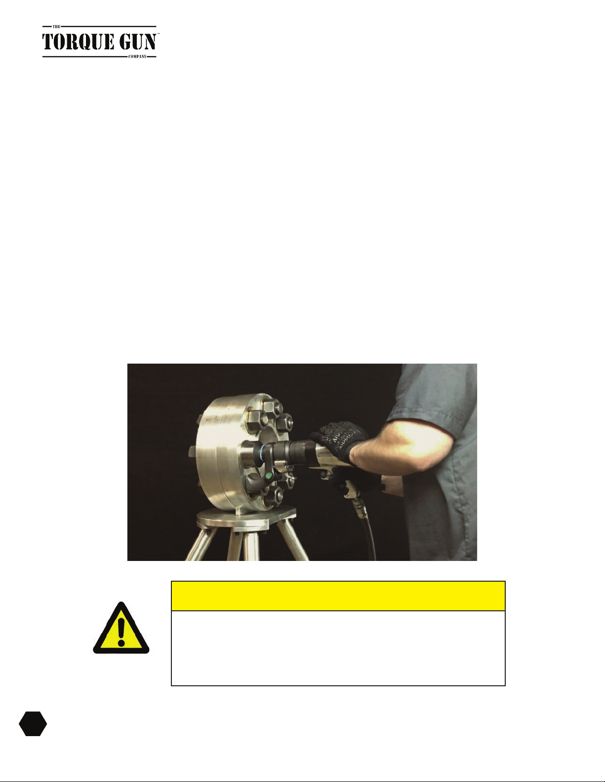
Figure 7 - High Speed (Impact) Rundown
Figure 8 - Maximum Torque Demonstration
• Hold the THRILL Gun securely as it tightens the nut down to the desired torque setting. Press
and hold the THRILL Gun trigger until you hear the motor stall. Repeat this step for all nuts
which need to be tightened to the specic torque value.
15
BREAKTHROUGH PRODUCTS FOR INDUSTRIAL BOLTING

Figure 9 - FRL Unit (Shown without silencer)
16 BREAKTHROUGH PRODUCTS FOR INDUSTRIAL BOLTING
FILTER/REGULATOR/LUbRICATOR
(FRL) UNIT OVERVIEW
A Filter/Regulator/Lubricator (FRL) Unit is provided with every jGun and must be used in conjunction with
the tool. In addition, the FRL Unit must be used with the 12’ hose provided for connection to the jGun to
ensure the tool’s durability. The FRL Unit removes water and foreign material from your air supply, regu-
lates the air pressure, and mixes pneumatic tool oil into the air to keep your jGun lubricated.
Operating the jGun without the FRL Unit will void the warranty and may cause damage to the air motor
and gearbox. Incorrect setting of the lubricator unit may result in a shortage of lubrication to the air mo-
tor and gearbox resulting in damage to the tool.
Personal Protective Equipment
Only qualied personnel who have thoroughly read this document may operate this tool. Failure to
safely operate this tool may result in serious injury or death.
• Inspect all FRL components as they are removed from the shipping container. If damage is found
to any component, contact your shipper immediately. Do not use the tool.
• Failure to follow correct tool usage could result in personal injury, co-worker injury, and/or dam-
aged tools and equipment.
• Ensure that your working area is clean and unobstructed before beginning work.

• FRL maintenance and repair must be performed by a qualied pneumatic technician.
• Modifying an FRL or FRL accessory is dangerous and invalidates the warranty.
• Inspect the unit before each use. Replace any obviously worn or damaged parts.
• When not in use, properly store the FRL, hoses and couplers.
• Analog gauges are standard to our FRL units. Digital gauges are not recommended for certain
applications. Please consult a Technical Representative before using a digital gauge unit.
Personal Protective Equipment
• Always wear the appropriate personal protective equipment when operating the FRL and jGun
including gloves, safety goggles, hearing protection, hard hat, and safety shoes
Air Supply Requirements
• Air supply line must be ½-inch minimum diameter to allow adequate air ow to the jGun
• Air supply must be 90 psi @ 30 cfm minimum.
• Ensure that air line ttings are tight and leak free. Do not over tighten air line ttings.
• Always use the FRL Unit provided with the jGun. Never use a substitute oiler and regulator with a
jGun.
• Open the air supply connected to the FRL unit and run the torque wrench while setting the pres-
sure on the gauge.
• Set the air pressure to the PSI needed to achieve desired torque shown on the provided pres-
sure/torque conversion chart.
• Open the air supply connected to the FRL unit and run the torque wrench while setting the pres-
sure on the gauge.
• Set the air pressure to the PSI needed to achieve desired torque shown on the provided
pressure/torque conversion chart.
NOTE
Set the air pressure while the tool is running as described in the Setup and Use section.
17
BREAKTHROUGH PRODUCTS FOR INDUSTRIAL BOLTING

Technical data and specifications are subject to change without notice.
18 BREAKTHROUGH PRODUCTS FOR INDUSTRIAL BOLTING
FRL SET UP AND USE
Proper setup and use of the FRL unit will ensure accurate results and safe operation. The three compo-
nents of the FRL must be checked individually to ensure correct operation.
• Empty the lter reservoir before use.
• If you are using a digital gauge, press the ZERO button on the regulator gauge before setting the
operating pressure.
• Adjust the lubricator ow properly.
• Fill the lubricator reservoir with pneumatic tool oil (provided with the FRL unit).
Important FRL Operating Procedures
• Only operate the unit with the air ow moving in the direction indicated by the arrows on top of
the unit.
• Empty the lter reservoir before each use to remove water and sediment.
• Fill the lubricator reservoir only with pneumatic tool oil before each use.
• Adjust the lubricator ow to one (1) drop per ten (10) seconds (shortage of lubrication may cause
motor to seize).
• Use only the hose provided with the FRL for connection to the unit; a change in hose length may
affect tool durability and accuracy.
Emptying the Filter Reservoir
You may empty the lter reservoir of water and foreign material in two ways:
• Emptying water through the release valve on the underside of the reservoir.
a. To use the release valve, push the valve until the water or debris drains out of the
reservoir.
• Removal of the reservoir. To remove the reservoir from the FRL unit:
a. Push down on the black square button to unlock the reservoir.
b. Twist the lter reservoir until the two lines on the FRL body and the lter reservoir
are aligned.

19
BREAKTHROUGH PRODUCTS FOR INDUSTRIAL BOLTING
Figure 10 - FRL Unit
c. Pull the lter reservoir down to detach from lubricator body.
d. Discard the contents of the lter reservoir.
Figure 11 - Detaching FRL Reservoir

20 BREAKTHROUGH PRODUCTS FOR INDUSTRIAL BOLTING
Figure 12 - FRL Unit, Lubricator 2/3rds Full of Oil
e. If needed, rell the reservoir as described on page 21.
f. Reattach the lubricator by aligning the lines on the lter reservoir and FRL body,
and pushing up on the reservoir, then twisting the reservoir to lock it in place. The
black locking button should snap into its original position.
Adjusting Air Pressure
To adjust the air pressure at the regulator:
1. If you are using a digital gauge, press the ON button on the gauge, then press the ZERO button
to set the reading to zero. Do not press the ZERO button when the system is under pressure.
2. A Torque Chart is provided with each tool which gives the conversion from air pressure (PSI) to
torque (ft-lbs and N-m). Use the chart to determine the air pressure needed to achieve desired
torque output.
3. Connect your air supply to the FRL, and press the ON button to view current air pressure.
4. While operating the tool, turn the regulator knob clockwise to decrease pressure and counter-
clockwise to increase pressure. Allow 30 seconds for the analog gauge to settle.
(Pressure Valve is regulated not to exceed 90 PSI)
Table of contents
Popular Power Tools manuals by other brands

EINHELL
EINHELL GC-CG 3,6 Li WT Original operating instructions

Sumake
Sumake S Series instruction manual

EINHELL Expert
EINHELL Expert TH-JS 650 E Original operating instructions

Electronica Technologies
Electronica Technologies EL700 manual

DeWalt
DeWalt DCE151 instruction manual

Parkside
Parkside 312142 Operation and safety notes

Greencut
Greencut GM650X Series instruction manual

Bush Hog
Bush Hog PHDHF15 Operator's manual

Clarke
Clarke CIR450 Operating & maintenance instructions

Balcrank
Balcrank Roughneck II 4110-022 Operation, installation, maintenance and repair guide

Stanley
Stanley XR DCD700D2 Original instructions

Drill Master
Drill Master XP user guide


